KSolare Mega Series User manual

Poonam petrol pump, KSolare Technology Park, Sr.No. 62,
Hissa No.03, Mangdewadi, Pune, Maharashtra 411046
Enquiry Email:
Service Email:
Contact:
8530111222
Follow Us On
Mega Series KSY -225KW-250KW

5G Mega
Series
225KSY, 250KSY
String Type PV Inverter
Qui
ck Installation Guide
CAUTION
1.The contents of this manual are subject to irregular updates
due to product upgrades or other reasons. Unless otherwis
e
agreed, this manual is only used as guidance. All statements
,
information and recommendations in the document do no
t
constitute any express or implied warranty.
2
.In any case, guidance in this manual cannot replace safet
y
warnings and instructions on user manuals and produc
t
fuselage.
3
.All operations of the equipment must be carried out b
y
professionals. Operators should be fully familiar with th
e
composition, working principles and standards of the whol
e
PV system.
4
.Before installing the equipment, check whether the delivery i
s
complete and whether the body has obvious external damag
e
according to the List of Accessories. If there are any missin
g
items or any damage, please contact the distributor.
5
.The following two situations occur and are not covered by t
he
warranty.
Remove the tamper-evident label;
Equipment damage caused by failure to store, handle
,
install, and use the equipment in accordance with th
e
requirements of this manual and the user manual.
1. Product Introduction
Scope of Supply
Inverter Hanging plate* M8 screw sets
MC4 PV- jack
+ pin
MC4 PV+ pin
+ jack
4# Allen wrench
M12 screw sets
*The hanging plate is fixed on the back of inverter.
The documents including:
Quick Installation Guide (this manual)
List of Accessories
Inspection Report
Certification
For the model and number of the accessories, please
refer to the List of Accessories.
This figure is only for reference; please refer to the
actual product.
Inverter front
1
2
(1) Door panel
(2) LED indicator
Port description
1
2
3
4
5
(1) DC switch
(2) PV- terminals
(3) PV+ terminals
(4) AC output terminal
(
5) RS485 interface
2. Installation Requirements
Installation Environment
Please install the inverter in a well ventilated
environment, avoid direct sunlight, rain and snow.
√Well ventilated
×Direct sunlight
×Rain and snow
≤60
≥-40
Ambient Temperature Relative humidity
5%~95%
(The inverter can reach the best working condition
when the temperature is lower than 40)
Inverter and hanging plate size
1000mm
760mm
320mm
Weight≤105kg
750mm
290mm
Installation Space
≥1000mm
≥
300mm
≥500mm
≥300mm
≥1000mm
Please install it vertically or tilt it backward at most 15°
to facilitate the heat dissipation of the inverter. Do not
install the inverter at an angle (forward, backward, or
sideways), horizontally, or upside down.
√
√
XX
<15°
3. Inverter Installation
Installation Steps
1. Unscrew the 4 fixing screws and keep them in a safe
place, and then take out the hanging plate.
2. According to the installation environment, choose a
suitable installation method to install the hanging plate.
Wall/Bracket Mounting
Expansion bolt (provide by customers)/screws (M8)
Wall/
Bracket
Wall/Bracket punching hole
Screw Rod Mounting
Screws
(M8)
Rod
Hoop Rod Mounting
Hoops
(Provided by
customers)
Rod
3. Hang the inverter on the hanging plate.
4. Reinstall the 4 fixing screws removed in the first
step.
4. Electrical Connections
DANGER
1. When connecting cables, do not operate live and
follow the relevant requirements in the Inverter's
Manual.
2. Before connecting the cable, please complete the
following preparations so as not to cause bodily
injury.
1) Disconnect the inverter DC switch. Ensure that
the inverter is in shutdown state and attach
warning signs.
2) Confirm the positive and negative pole of the
input cable and mark it well. Make sure the
connection between input cable and PV cluster
is broken.
3) It is confirmed that the open circuit voltage of PV
cluster does not exceed the specified limit.
4) Confirm that the corresponding AC box circuit
breaker is in a state of disconnection.
3. When connecting the input cable, ensure that the
positive and negative poles of the input cable
correspond to the positive and negative poles of
the PV terminals of the series inverter.

Cable Selection
Name
Recommended Cable Specifications
PV branch input cable Industry general PV cable, model:
PV1-F
It is recommended to use a cable with a
cross-section of 4.0 mm2 for each PV+
and PV- branch.
AC output cable 3 core outdoor cable (A, B, C)
Recommended cross sectional area of
conductor (copper): 70 mm
2
RS485 communication
cable
It is recommended to use a special
communication cable or 4-core or 2-core
shielded twisted pair cable with a
cross-sectional area of not less than
0.75 mm
2
.
PE ground cable It is recommended to use at least one
grounded dedicated cable with a
cross-sectional area of 35 mm
2
.
Note:
1. The AC output has only 1 waterproof locks with a specification
of 65mm~70mm.
2. The RS485 communication cable has only one waterproof
lock and the size is 18mm~25mm.
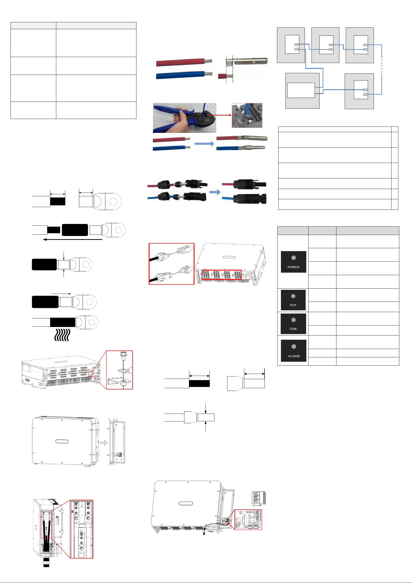
Output side cable connection
1. Crimping the OT terminal. Users need to prepare
the OT terminals themselves. The OT terminal
model of PE is M6, and the model of AC is M12.
1) Strip the front end of the cable core.
OT terminal
Cable
LL+(2~3)mm
2) Put on the heat shrink tubing and OT terminal.
Heat shrink tubing
3) Crimp the OT terminal.
4) Move the heat shrink tubing forward to cover
the seam.
5) Use a dryer to heat the sleeve to make it tight.
2. Ground connection:
Note: The ground cable must be reliably connected to the
grounding bar.
3. DC output cable connection:
a) Open the inverter right door panel.
b) Screw off the locking cap of the AC output
waterproof lock and take out the seal baffle..
c) The AC cables are connected to A, B, C of the
AC terminal row in turn. Fasten the locking
cap after completion.
A
B
C
PV Input Cable Connection
1. Crimp MC4 terminal:
1) Confirm the positive and negative terminals of
the input cable and mark them.
Note: Please do not judge by the color of the cable
only, be sure to refer to the actual measurement.
2) Stripping with a wire stripper;
Stripping length
requirement
positive
negative
3) Press the cable together with the
corresponding core according to the correct
polarity.
Crimp
method
Positive
Negative
4) Insert the core into the male and female ends
of the MC4 connector and tighten the
connector back cover according to the correct
polarity.
Positive
Negative
2. Remove the sealing plugs of the input terminals at
the bottom of the inverter. Connect the positive
and negative terminals of each input cable to the
PV+ and PV- input terminals of the inverter one by
one. Insert it until you hear a "click".
3. If there are unconnected input terminals, please
confirm that the unconnected input terminals
remain sealed by the plug.
RS485 Communication Cable Connection
On the RS485 adapter board X1, two RS485 interfaces
(labeled P1, P2) are shown. This interface is used to
connect adjacent inverters.
1. Crimp the 485 terminal. Users need to prepare the
terminals themselves, and the terminals model
needs to match the 485 cable selected.
1) Strip the front end of the cable core.
Terminal
Cable L
L
2) Insert the terminal and crimp.
2. Unscrew the RS485 waterproof lock cap and take
out the seal baffle.
3. Pass the RS485 cable through the waterproof lock
and connect it to the interface P1, P2 on the
RS485 adapter board X1. Tighten the locking cap
after completion. (The dotted line indicates the
wire inside the inverter)
P2
P1
3PIN: 485-
2PIN: PE
1PIN: 485+
4. Close the right door panel and screw the screws.
The connection of multiple inverters is suggested to be
connected in series in the following diagram.
1# inverter
X1
2# inverter 3# inverter
N# inverter
Data collector
Follow
this
mode
in
series
P2
P1
X1
P2
P1
X1
P2
P1
X1
P2
P1
485 interface
485 interface
5. Post-installation Check
1. Confirm that the inverter is securely installed in place
2. Check if the ground wire is properly connected,
whether the connection is reliable and secure, and
ensure that there is no open-circuit or short-circuit
3. Check that the output cable is properly connected, that
the connection is reliable and secure, and that there is no
open-circuit or short-circuit.
4. Check whether the DC input cable connection polarity
is correct, whether the connection is reliable and secure,
and ensure that there is no open-circuit or short-circuit.
5. Check if the RS485 communication cable connection is
correct and reliable.
6. Check if the inverter's right door panel is closed and
the door panel screws are tightened.
7. Check if the DC input terminals that are not needed are
sealed
6. LED indicators Description
Indicator Status Meaning
Light on Both PV side and grid side
are normal
Light flash Grid side is normal, PV side
is abnormal
Light slow
flash
PV side is normal, grid side is
not connected
Light off Both PV side and grid side
are not connected
Light on Inverter is in operation
Light off Inverter is not in operation
Light slow
flash Communication is normal
Light off Communication is abnormal
Light slow
flash Prompt warning
Light flash Abnormal warning
Light on Fatal warning
Ksolare Energy Private Ltd.
Factory & Marketing Office
Ksolare Technology Park Sr.No.62,
Hissa No.03, Mangdewadi, Pune-Satara
Road, Katraj, Pune-411046. (MH-India)
Sales: 7888009284/85/86
Service: 8530111222
Email: sales@ksolare.com
www.ksolare.com

Poonam petrol pump, KSolare Technology Park, Sr.No. 62,
Hissa No.03, Mangdewadi, Pune, Maharashtra 411046
Enquiry Email:
Service Email:
Contact:
8530111222
Follow Us On
This manual suits for next models
2
Popular Water Pump manuals by other brands

Sulzer
Sulzer RCP 250 Installation and operating instructions

AMT
AMT 2762-98 1-1/2HP Specifications information and repair parts manual

VT
VT Econo 2000 User instructions

Enerpac
Enerpac Spartan PMU10022 instruction sheet

Forester
Forester FVP-250 instruction manual

ITT
ITT E1-BCANCT1W-06 Installation & operating manual

STAR Water Systems
STAR Water Systems SJ05 instructions

GORMAN-RUPP PUMPS
GORMAN-RUPP PUMPS 81 2D11-B Installation, operation and maintenance manual

Wilo
Wilo Wilo-Yonos PICO-STG Series Installation and operating instructions

Zoeller
Zoeller 53 Series installation instructions

Neptune Systems
Neptune Systems COR-15 user guide

Ironton
Ironton 750131 owner's manual