KST SILVER PLUS 345-000 Datasheet

1
Instructions - Parts List
SILVER PLUS Gun (345-000)
5000 psi ( 345 bar, 34.5 MPa) Maximum Working Pressure
The spray tip is not included with the gun. Order the tip separately
Korean Spray Technology Co., Ltd.
#6036, Daejeo-2ong, Gangseo-Gu,
Busan, S. Korea. (618-817)
Tel: 82-70-7600-9630
Fax: 82-51-312-0991
e-mail : kst0991@naver.com
http://www.kstspray.com
This manual contains important warning and
information.
Read and keep reference.

2
WARNING
INJECTION HAZARD
Spray from the spray gun, hose leaks or ruptured
components can inject fluid into your body and
cause extremely serious injury, including the need for
amputation. Splashing fluid in the eyes or on the
skin can also cause can also cause serious injury.
_ Fluid injected into the skin is a serious injury. The injury
may look like just a cut, but it is a serious injury. Get
immediate medical attention.
_ Do not point the gun at anyone or any part of the body.
_ Do not put hand or fingers over the spray tip.
_ Do not stop or deflect leaks with your hand, body, glove
or rag.
_ Do not “blow back” fluid; this is not an air spray system.
_ Always have the tip guard on the spray gun when
spraying
_ Check the spray gun diffuser (if so equipped) operation
weekly. Refer to the gun manual.
_ Be sure the spray gun safety knob operates before
operating the gun.
_ Lock the spray gun safety knob when you stop spraying.
_ Follow the Pressure Relief Procedure on page 3 when
you are instructed to relieve pressure, stop spraying,
check, clean or service any system equipment, or
install or change spray tips.
_ Tighten all fluid connections before each use.
_ Check the hoses, tubes and couplings daily. Replace
worn or damaged parts immediately. Permanently
coupled hoses cannot be repaired.
_ Handle and route hoses and tubes carefully. Keep hoses
and tubes away from moving parts and hot surfaces.
Do not use the hoses to pull equipment. Do not
expose KST hoses to temperatures
above 150_F (66_C) or below –40_F (–40_C).
EQUIPMENT MISUSE HAZARD
Equipment misuse can cause the equipment to rupture,
malfunction, or start unexpectedly and result in
serious injury.
_ This equipment is for professional use only.
_ Read all instruction manuals, tags, and labels before
operating the equipment.
_ Use the equipment only for its intended purpose. If
you are uncertain about the usage, call your
distributor.
_ Do not alter or modify this equipment. Use only
genuine KST parts and accessories.
_ Check the equipment daily. Repair or replace worn or
damaged parts immediately.
_ Do not exceed the maximum working pressure of the
lowest rated system component. This equipment as a
5000 psi (345bar) maximum working pressure.
_ Do not lift pressurized equipment.
_ Route the hoses away from the traffic areas, sharp
edges, moving parts, and hot surfaces. Do not
expose KST hoses to temperatures above 150_F
(66_C) or below –40_F (–40_C).
_ Do not use the hoses to pull the equipment.
_ Use fluids or solvents that are compatible with the
equipment wetted parts. See the Technical Data
section of all the equipment manuals. Read the fluid
and solvent manufacturer’s warnings.
_ Fluid hoses must have spring guards on both ends to
protect them from rupture caused by kinks or bends
near the couplings.
_ Comply with all applicable local, state and national
fire, electrical and other safety regulations.
TOXIC FLUID HAZARD
Hazardous fluids or toxic fumes can cause a serious injury
or death if splashed in the eyes or on the skin, inhaled,
or swallowed.
_ Know the specific hazards of the fluid you are using.
_ Store hazardous fluid in an approved container. Dispose
hazardous fluid according to all local, state and national
guidelines.
_ Always wear protective eyewear, gloves, clothing and
recommended by the fluid and solvent manufacturer.
FIRE AND EXPLOSION HAZARD
Improper grounding, poor air ventilation, open flames,
or sparks can cause a hazardous condition and result
in fire or explosion and serious injury.
_ Ground the equipment and the object being sprayed.
See Electrical Grounding on page 3.
_ Provide fresh air ventilation to avoid the buildup of
flammable fumes from solvent or the fluid being
sprayed.
_ Extinguish all the open flames or pilot lights in the
spray area.
_ Electrically disconnect all the equipment in the spray
area.
_ Keep the spray area free of debris, including solvent,
rags, and gasoline.
_ Do not turn on or off any light switch in the spray area
while operating or if fumes are present.
_ Do not smoke in the spray area.
_ Do not operate a gasoline engine in the spray area.
_ If there is any static sparking while using the
equipment, stop spraying immediately. Identify and
correct the problem.
MOVING PARTS HAZARD
Moving parts, such as the air motor piston and the
secondary pump lever and connecting rod area, can
pinch or amputate fingers.
_ Do not operate the equipment with the air motor plates
removed.
_ Keep your body and tools clear of any moving parts
when starting or operating the equipment.

3
Installation
! WARNING
INJECTION HAZARD
To reduce the risk of a serious injury,
always follow the Pressure Relief Procedure
on page 3 whenever you are
instructed to relieve the pressure.
FIRE AND EXPLOSION HAZARD
To reduce the risk of static sparking, which can cause a
fire or explosion and result in serious injury, including
electric
shock, and property damage, always follow these
Precautions.
_ Read and follow the warnings in FIRE and EXPLOSION
HAZARD on page 2.
_ Provide electrical grounding continuity throughout
the entire spray system as instructed below.
_ Have a trained and qualified person perform all
electrical wiring.
_ Comply with all applicable local, state and
national fire, electrical and other safety
regulations.
INJECTION HAZARD
Your spray system must have a bleed type
master air valve and a fluid drain
valve. These two accessories help reduce
the risk of serious injury, including fluid injection,
splashing in the eyes or on the skin, or injury
from moving parts, if you are adjusting or repairing
the pump or gun.
1. Connect a grounded fluid hose to the gun fluid inlet.
2. Without the spray tip installed, start the pump or sprayer and flush and prime it according to the pump or sprayer instructions.
3. Relieve the pressure.
4. With the gun safety Trigger lock, unscrew the tip guard (1) and install the tip (2) and filter assembly (3) in the tip guard nut. Screw the
assembly firmly onto the gun. Tighten with a wrench. See Fig. 1.
5. Strain the fluid you are spraying if it contains particles which clog the spray tip.
FIG1.
Required Accessories
1. The bleed-type master air valve relieves air trapped between this valve and the pump after the air regulator is shut off. Trapped air can
cause the pump to cycle unexpectedly.
2. The fluid drain valve assists in relieving fluid pressure in the displacement pump, hose and gun; triggering the gun to relieve pressure may
not be sufficient.
Electrical Grounding
1. Provide electrical grounding for the pump or sprayer as instructed in its separate manual.
2. Provide electrical grounding for the air compressor or hydraulic power supply according to the local code and the manufacturer’s
recommendations.
3. Use only electrically conductive fluid hoses with a maximum of 500 feet (150 m) combined hose length to ensure grounding continuity.
4. Obtain electrical grounding continuity for the spray gun by connecting it to a properly grounding fluid hose and pump or sprayer.
5. Provide electrical grounding for these components according to the local code: the fluid supply container, the object being sprayed, and
all of the solvent pails used when flushing. Use only metal pails, which are conductive. Do not place the pail on a non-conductive surface,
such as paper or cardboard, which interrupts the grounding continuity.
6. To maintain grounding continuity when flushing or relieving pressure, always hold a metal part of the gun firmly to the side of a
grounded metal pail, then trigger the gun.
Operation
Pressure Relief Procedure
- To reduce the risk of serious bodily injury, including fluid injection, splashing fluid or solvent in the eyes or on the skin, or injury from moving
parts or electric shock, always follow this procedure whenever you shut off the sprayer, when checking or servicing any part of the spray
system, when installing, cleaning or changing spray tips, and whenever you stop spraying.
1. Lock the gun trigger safety.
2. Shut off the power supply to the pump and close any bleed-type master air valves.
3. Unlock the gun trigger safety. Hold a metal part of the gun firmly to the side of a grounded metal pall, and trigger the gun to relieve pressure.
4. Lock the gun trigger safety.
5. Open the pressure drain valve(required in system), having a container ready to catch the drainage.
6. Leave the drain valve open until you are ready to spray again.
If you suspect that the spray tip or hose is completely clogged or that pressure has not been fully relieved after following the steps above,
VERY SLOWLY loosen the tip guard retaining nut or hose end coupling and relieve pressure gradually, then loosen completely. Now clear the
tip or hose .

4
Startup
1. Start the pump. Adjust the fluid pressure so the spray is completely atomized. Always use the lowest pressure necessary to get the desired
results. Higher pressure may not improve the spray pattern and will cause premature tip and pump wear.
2. If adjusting the pressure does not give a good spray pattern, try another size tip. Relieve the pressure before changing a spray tip.
3. Use a full-open, full-close trigger action. Hold the gun about 14 inches (350 mm) from and at right angles to the work surface. Don’t swing
the gun in an arc. Practice to find the best length and speed of stroke.
How to Adjust the Spray Pattern
1. Relieve the pressure.
2. Loosen the tip guard retaining nut.
3. Turn the spray tip so the groove is horizontal for a horizontal spray pattern and vertical for a vertical pattern. See Fig. 1.
4. The spray tip orifice size and spray angle determines the coverage and size of the pattern. When more coverage is needed, use a larger
spray tip rather than increasing the fluid pressure.
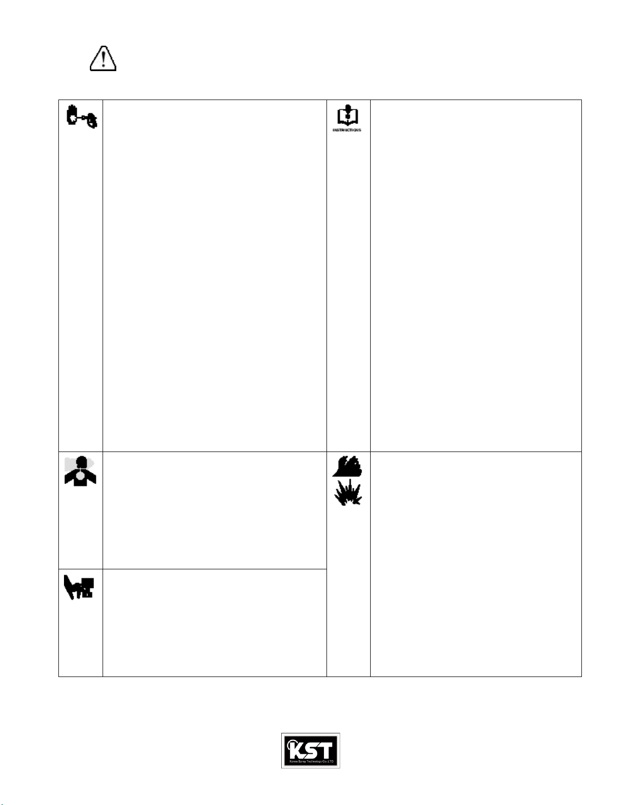
! WARNING
INJECTION HAZARD
To reduce the risk of an injection or splashing fluid in the
eyes or on skin, follow these precautions before removing,
cleaning or changing a spray tip or tip guard.
_ Do not hold your hand, body, or rag in front of the spray
tip when cleaning or checking a clogged tip.
_ Always point the gun toward the ground or into a waste
container when checking to see if the spray tip is
cleared.
_ Do not try to “blow back” paint; this is NOT an air spray
gun.
_ Follow the Pressure Relief Procedure on page 3 before
wiping the fluid buildup off the gun or spray tip, before
removing the tip guard or the spray tip, and whenever
you are instructed to relieve the pressure.
FIRE AND EXPLOSION HAZARD
To reduce the risk of a serious injury from fluid injection,
static sparking, or splashing fluid in the eyes on or the
skin, follow these precautions when flushing.
_ Be sure the entire system and the flushing pails are
properly grounded. Refer to Electrical Grounding on
page 3.
_ Remove the spray tip from the gun.
_ Use the lowest possible fluid pressure.
_ Maintain firm metal-to-metal contact between the gun
and pail during flushing.
_ Follow the Pressure Relief Procedure on page 4
whenever you are instructed to relieve pressure.
How to Clear or Clean a Clogged Spray Tip.
NOTE: Clean the tip frequently during the daily operation and at the end of the work day. This helps keep fluid buildup from drying and
clogging the spray tip.
1. Relieve the pressure.
2. Use a solvent–soaked brush to clean the tip.
3. Remove the tip (25) and the filter (26). See Fig. 1.
4. Blow out the tip obstruction with air from the front of the spray tip, or soak the spray tip and gun nozzle long enough to dissolve the
obstruction. If the clog won’t dissolve, tap the back of the spray tip against a flat surface to remove it.
How to Flush the Gun.
Always flush the pump and the gun before the fluid being sprayed can dry in it.
NOTE: If it is available, the flushing procedure provided in your pump or sprayer manual should be
used instead of this procedure.
1. Follow the Pressure Relief Procedure, page 3. Remove the tip guard and spray tip. Soak and clean the parts.
2. Put the pump intake in a grounded pail of water of solvent. Start the pump at its lowest pressure.
3. Trigger the gun into the original pail. When solvent appears, release the trigger.
4. Now trigger the gun into the solvent pail. Circulate the fluid until the system is thoroughly flushed.
5. Follow the Pressure Relief Procedure, page 2.
Service
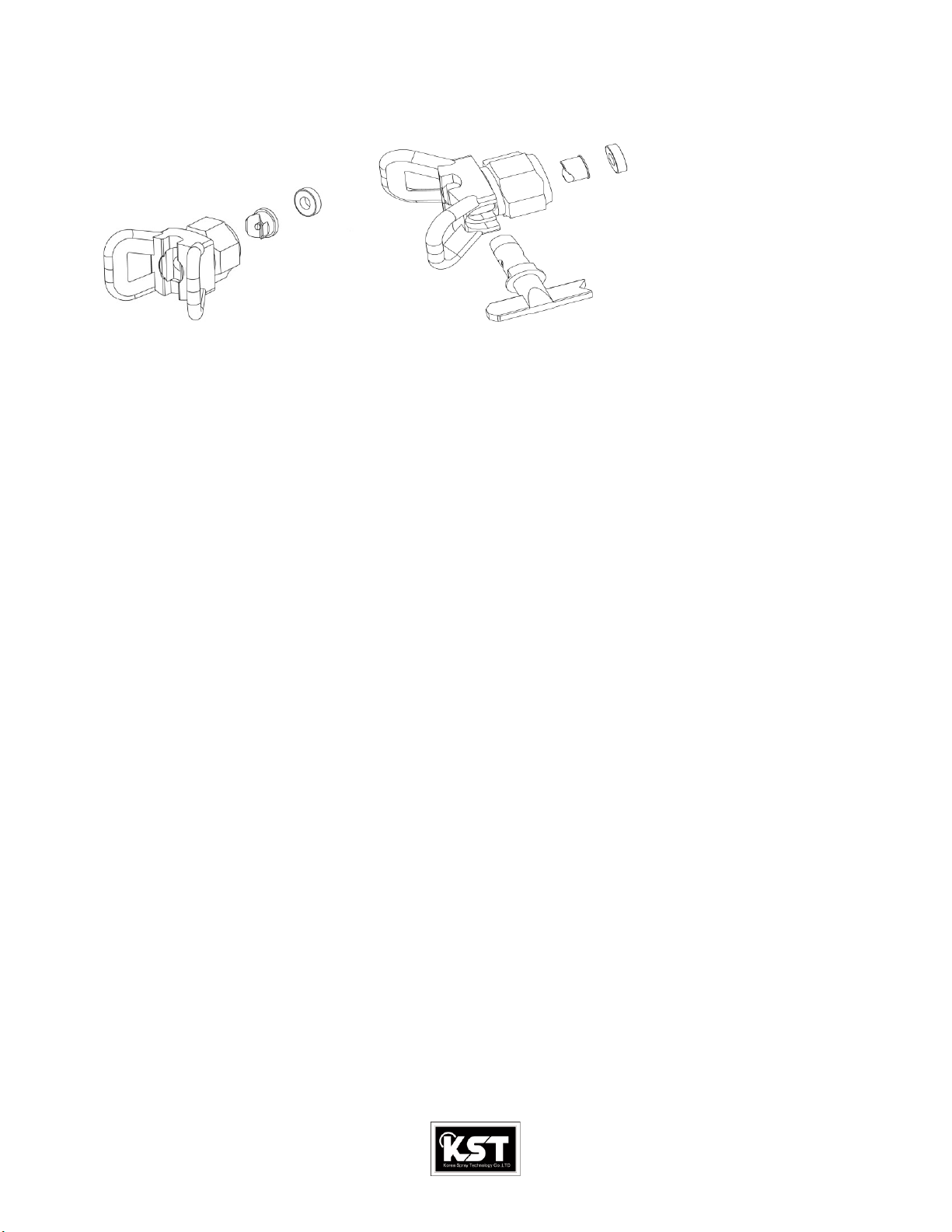
Needle Replacement. Fig.2
1. Follow the Pressure Relief Procedure, page 3.
2. Remove the hose, tip guard, spray tip and gasket. Fig.3
3. Remove the diffuser/seat(6), and gasket(7). Remove the screw(12), pivot pin(13), and trigger(14), page 5.
4. Insert a punch into the rear of the gun and tap it to push the needle(8), out the front of the gun. See Fig 2
5. Clean the internal passages of the gun.
6. Grease the rings(A) of the new needle(8). See Fig.3
7. Side the rear of the needle(8), into the front of the gun. Side the(B), provided with the repair kit, into the gun,
Around the needle. Lightly tap the tool with a hammer or lightly press the tool against a flat surface to seat the
Needle. See Fig. 4. Remove the tool.
- CAUTION: Tapping or pressing the tool too hard may jam the tool and damage the needle.
8. Grease the end of the needle.
9. Grease the diffuser/seat threads. Place the new gasket(7), on the diffuser/seat(6), and screw the assembly into the
Fluid housing(11), Torque to 20-25ft-lb(27-34N.m). See Fig. 4
10. Install the trigger(14), pivot pin(13), and screw(12). page 5.
Fig.4
8
B
8

5
Parts
No
Code
Description
Qty
No
Code
Description
Qty
1
345-01
TIP GUARD
1
9
345-09
SCREW
2
2
345-02
TIP
1
10
345-10
SET SCREW
1
3
345-03
TIP FILTER
1
11
345-11
FLUID HOUSING
1
4
345-04
HOUSING
1
12
345-12
SCREW
1
5
345-05
GASKET
1
13
345-13
PIN
1
6
345-06
SEAT
1
14
345-14
TRIGGER
1
7
345-07
GASKET, copper
1
15
345-15
HANDLE
1
8
345-08
NEEDLE ass’y
1
16
345-16
SPRING PIN
1
Note : part marked in color are the option parts
Replacement Danger and Warning labels, tags and cards
are available at no cost.
These parts are included in repair kit which may be purchased separately.
Always use genuine KST parts.

6
Option Tip GUARD & Switch Tip
Technical Data
Maximum Fluid
Working pressure 5000 psi (345 bar)
Fluid Inlet 1/4 npsm

7
KST Standard Warranty
KST warrants all equipment referenced in this document which is manufactured by KST and bearing its name to be free from
defects in material and workmanship on the date of sale to the original purchaser for use. With the exception of any special, extended,
or limited warranty published by KST, KST will, for a period of twelve months from the date of sale, repair or replace any part of the
equipment determined by KST to be defective. This warranty applies only when the equipment is installed, operated and maintained
in accordance with KST written recommendations.
This warranty does not cover, and KST shall not be liable for general wear and tear, or any malfunction, damage or wear caused by
faulty installation, misapplication, abrasion, corrosion, inadequate or improper maintenance, negligence, accident, tampering, or substitution
of non–KST component parts. Nor shall KST be liable for malfunction, damage or wear caused by the incompatibility of
KST equipment with structures, accessories, equipment or materials not supplied by KST, or the improper design, manufacture,
installation, operation or maintenance of structures, accessories, equipment or materials not supplied by KST.
This warranty is conditioned upon the prepaid return of the equipment claimed to be defective to an authorized KST distributor for
verification of the claimed defect. If the claimed defect is verified, KST will repair or replace free of charge any defective parts. The
equipment will be returned to the original purchaser transportation prepaid. If inspection of the equipment does not disclose any defect
in material or workmanship, repairs will be made at a reasonable charge, which charges may include the costs of parts, labor, and
transportation.
THIS WARRANTY IS EXCLUSIVE, AND IS IN LIEU OF ANY OTHER WARRANTIES, EXPRESS OR IMPLIED, INCLUDING
BUT
NOT LIMITED TO WARRANTY OF MERCHANTABILITY OR WARRANTY OF FITNESS FOR A PARTICULAR PURPOSE.
KST sole obligation and buyer’s sole remedy for any breach of warranty shall be as set forth above. The buyer agrees that no other
remedy (including, but not limited to, incidental or consequential damages for lost profits, lost sales, injury to person or property, or any
other incidental or consequential loss) shall be available. Any action for breach of warranty must be brought within one (1) years of the
date of sale.
KST MAKES NO WARRANTY, AND DISCLAIMS ALL IMPLIED WARRANTIES OF MERCHANTABILITY AND FITNESS
FOR A PARTICULAR PURPOSE, IN CONNECTION WITH ACCESSORIES, EQUIPMENT, MATERIALS OR
COMPONENTS SOLD
BUT NOT MANUFACTURED BY KST.These items sold, but not manufactured by KST (such as electric motors, switches,
hose, etc.), are subject to the warranty, if any, of their manufacturer. KST will provide purchaser with reasonable assistance in making
any claim for breach of these warranties.
In no event will KST be liable for indirect, incidental, special or consequential damages resulting from KST supplying equipment
hereunder, or the furnishing, performance, or use of any products or other goods sold hereto, whether due to a breach of contract,
breach of warranty, the negligence of KST or otherwise.
KST Information
TO PLACE AN ORDER OR FOR SERVICE, contact your KST distributor, or call these numbers to identify the nearest
distributor.
Korean Spray Technology Co., Ltd.
#6036, Daejeo-2dong, Gangseo-Gu,
Busan, S. Korea. (618-812)
Tel: 82-70-7600-9630
Fax: 82-51-312-0991
Table of contents