KTM 45129075000 Service manual

Information
Hard Equipment
Bedienungs- und Montageanleitung Drehzahlmesser
Tachometer operating and mounting instructions
Istruzioni di Montaggio ed Uso Contagiri
Notice de montage et d'utilisation compte-tours
Bedienungs- und Montageanleitung Drehzahlmesser
KTM Teilenummer / Partnumber / Cod.art. / Référence / Número de la pieza KTM
45129075000
03.2005

KTM KANN NICHT VERANTWORTLICH GEMACHT WERDEN FÜR FALSCHE MONTAGE ODER VERWENDUNG DIESES PRODUKTS. Bitte
befolgen Sie die Montageanleitung. Wenn bei der Montage Unklarheiten auftreten, wenden Sie sich bitte an eine KTM Fachwerkstätte.
Danke
Danke, daß Sie sich für KTM Hard Equipment entschlossen haben.
Alle unsere Produkte wurden nach den höchsten Standards entwickelt und gefertigt, unter Verwendung der besten verfügbaren
Materialien.
KTM Hard Equipment ist rennerprobt und gewährleistet ultimative Performance.
KTM WILL NOT BE HELD LIABLE FOR IMPROPER INSTALLATION OR USE OF THIS PRODUCT. Please follow all instructions provided. If you
are unsure of any installation procedure, please contact a certified KTM dealer.
Thank you.
Thank you for choosing KTM Hard Equipment!
All of our products are designed and built to the highest standards using the finest materials available.
KTM Hard Equipment is race proven to offer the ultimate in performance.
KTM NON PUÒ ESSERE RESA RESPONSABILE PER UN MONTAGGIO O USO IMPROPRIO DI QUESTO PRODOTTO. Per favore osservate le
istruzioni nel manuale d'uso.Se dovessero sorgere dei dubbi al montaggio, rivolgetevi ad un'officina specializzata KTM.
Grazie.
Grazie per aver deciso di acquistare un prodotto KTM Hard Equipment.
Tutti i nostri prodotti sono stati sviluppati e realizzati secondo i massimi standard e con l'impiego dei migliori materiali disponibili.
Il KTM Hard Equipment è collaudato nelle competizioni ed assicura altissime prestazioni.
LA RESPONSABILITÉ DE KTM NE SAURAIT ÊTRE ENGAGÉE EN CAS D'ERREUR DANS LE MONTAGE OU L'UTILISATION DE CE PRODUIT.
Il convient de respecter les instructions de montage.
Si quelque chose n'est pas clair lors du montage, il faut s'adresser à un agent KTM.
Merci
Nous vous remercions d'avoir choisi KTM Hard Equipment.
Tous nos produits ont été développés et réalisés selon les plus hauts standards et en utilisant les meilleurs matériaux disponibles.
KTM Hard Equipment a été testé en compétition et garantit les plus hautes performances.
DEUTSCH
2
ENGLISH
2
ITALIANO
2
FRANCAIS
2

DEUTSCH
3
– Für den Werkstattgebrauch bringen Sie das selbstklebende Stück des
Magnetbandes an der Rückseite des Drehzahlmessers an. Das ermö-
glicht ein schnelles Anbringen und Entfernen des Messers auf
Metalloberflächen während der Prüfung.
– Für dauerhaften Einbau verwenden Sie den Drehzahlmessers als
Schablone, um die Montagelöcher zu markieren, bohren Sie zwei
2,5mm Löcher.
– BOHREN SIE NICHT IN BENZINTANKS ODER MOTORGEHÄUSE.
– Im Zweifelsfall setzen Sie sich mit Ihrer KTM- Fachwerkstätte in
Verbindung.
– Wenn Sie den Drehzahlmessers am Armaturenbrett montieren, boh-
ren Sie ein 3mm starkes Loch für das Fühlerkabel zum Durchführen
durch das Amaturenbrett.
Montage
– Suchen Sie zur Fixmontage einen geeigneten Platz für den
Drehzahlmesser, wo er im Blickfeld des Bedieners oder leicht zugän-
glich ist.
– Stellen Sie sicher, dass das Fühlerkabel das Zündsteckerkabel
erreicht.
– Das Fühlerkabel kann durch einen Standard 18 Litzendraht bis zu
182 cm lang ersetzt werden
– Das Messgerät sollte nicht näher als 10 cm zum Zündungskabel mon-
tiert werden.
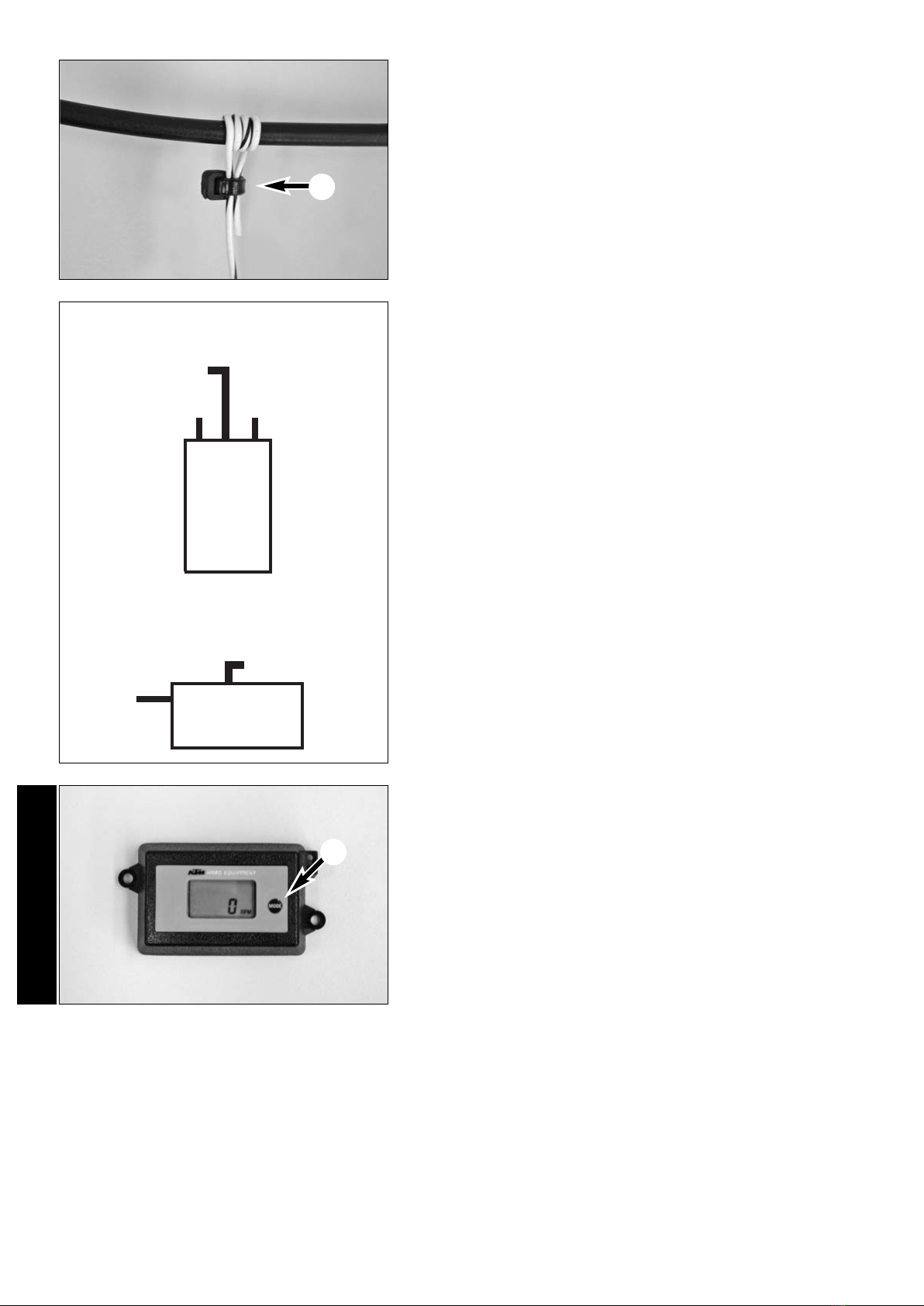
– Bringen Sie das Kabel [1] am Messer an, indem Sie es von der
Rückseite des Messers durch das Loch und danach zurück in das 2.
Loch führen und fest anziehen.(siehe Abbildung A)
– Ziehen Sie NICHT die Isolierung des Fühlerkabels ab. Die Ader darf
keine Verbindung oder elektrischen Anschluss herstellen.
– Schrauben Sie den Messer mit den mitgelieferten Schrauben fest.
ANSCHLUSS VARIANTE 1:
Klemmen Sie die Krokoklemme [2] einfach an das Zündkabel.
1
AHINWEIS: Führen Sie das Fühlerkabel zur Zündspule/Zündkabel nicht umge-
kehrt. Führen Sie das Fühlerkabel NICHT zusammen mit anderen Kabeln
oder entlang großer Metallflächen, da es die Messtätigkeit beeinflussen
kann.
2

Betrieb / Funktionen
Drücken Sie kurz die Taste MODE [2], Sie sehen für 3 Sekunden auf der
rechten Seite des Displays P1, P2, oder P3. Das ist der derzeit programmierte
Zündvorgang. Um zu MAXTACH (höchste Motordrehzahl) zu kommen, hal-
ten Sie die MODE Taste mindestens 3 Sekunden lang gedrückt.
Um die höchste Drehzahl zu löschen, halten Sie die Taste mindestens 9
Sekunden lang gedrückt (Es erscheint am Display 0000).
Um den Zündvorgang zu ändern, halten Sie die Taste MODE mehr als 10
Sekunden lang gedrückt, lassen Sie die Taste beim gewünschten Zündvorgang
(P1, P2, oder P3) aus.
P1 – für die meisten 1-Zylinder 2-Takt Motoren (bis 16.000 U/min)
P2 – für Mehrpunktzündanlagen (mehrere Zündungen / Umdrehung; bis
8.500 U/min)
P3 – für 4-Takt Motoren (bis 16.000 U/min)
Display Updatezeit – 1,5 Sekunden
ANSCHLUSS VARIANTE 2:
Wickeln Sie das Fühlerkabel 4mal um das Zündsteckerkabel und fixieren
Sie es wie auf dem Bild dargestellt mit einem Kabelbinder [1].
ANSCHLUSS VARIANTE 3:
Der direkte Anschluss an der Zündspule ermöglicht das genauste
Messergebnis. Verbinden Sie dazu das am Ende abisolierte Fühlerkabel
mit der Primärseite der Zündspule.
Das Fühlerkabel kann, falls notwendig, durch einfaches Abschneiden
gekürzt werden.
Zündspule
+– Von Batterie
Primärseite
DEUTSCH
4
1
2
Zündkabel
Primärseite
Not Aus Schalter
Zündkabel
Zündspule
Magnetzündung
Batteriezündung

Montage
– To permanently mount the tachometer, find a position where it is easily
visible or accessible to the driver.
– Make sure the sensor cable reaches the ignition cable.
– The sensor cable can be replaced by a standard 18-stranded wire up
to 182 cm long.
– The gauge should not be mounted closer than 10 cm from the igni-
tion cable.
– For workshop use, apply the self-adhesive part of the magnetic tape
to the back of the tachometer. This will make it possible to quickly
place the gauge on metal surfaces and remove while testing.
– For permanent mounting, use the tachometer as a template to mark
the mounting holes and drill two 2.5 mm holes.
– DO NOT DRILL INTO THE FUEL TANK OR THE ENGINE CASE.
– If you have any questions, contact your authorized KTM workshop.
– If you mount the tachometer on the instrument panel, drill a 3 mm
hole in the instrument panel to be able to run the sensor cable through.
CONNECTION VERSION 1:
Simply clamp the alligator clip [2] onto the ignition cable.
– Connect the cable [1] to the gauge by pushing it through the hole in
the gauge from behind and then back through the 2nd hole and tigh-
ten(see illustration A).
– Be careful NOT to pull off the insulation on the sensor cables. The
conductor may not establish an electric connection.
– Fasten the gauge with the screws included in the scope of supply.
NOTE: run the sensor cable to the ignition coil/ignition cable, not the other
way around.
Do NOT run the sensor cable together with other cables or along larger
metal surfaces since this can affect the measuring accuracy.
ENGLISH
5
1
A
2

CONNECTION VERSION 2:
Wind the sensor cable around the ignition cable 4 times and fasten with
a cable clip [1] as shown in the illustration.
CONNECTION VERSION 3:
A direct connection to the ignition coil will give you the most accurate
measuring result. Strip the insulation on the end and connect the sensor
cable to the primary side of the ignition coil.
If necessary, you can shorten the sensor cable by simply cutting part of
it off.
Operation / Functions
Briefly press the MODE button [2]. P1, P2, or P3 will be displayed on the
right side for 3 seconds. This is the currently programmed ignition set-
ting. To access MAXTACH (maximum engine speed), press and hold the
MODE button for at least 3 seconds.
To delete the maximum speed, press and hold the button at least 9
seconds (0000 will appear in the display).
To change the ignition setting, press and hold the MODE button longer
than 10 seconds and release the button at the desired ignition setting
(P1, P2, or P3).
P1 - for most 1-cylinder, 2-stroke engines (up to 16,000 rpm)
P2 - for multipoint ignition systems (multiple ignitions/revolutions; up to
8,500 rpm)
P3 - for 4-stroke engines (up to 16,000 rpm)
Display update time - 1.5 seconds
ENGLISH
6ignition coil
+– from the battery
primary side
1
2
ignition cable
primary side
ignition cable
ignition coil
magneto ignition
battery ignition
emergency off
switch

Montaggio
– Per il montaggio fisso cercare un posto adatto dove il contagiri sia ben
visibile ed accessibile all'utente.
– Assicurarsi che il cavo contagiri raggiunga il cavo d'accensione
– Il cavo contagiri può essere sostituito da un cavo Litz standard a 18
fili intrecciati lungo fino a 182 cm.
– Il contagiri dovrebbe essere montato almeno ad una distanza di 10
cm dal cavo d'accensione.
– Per l'uso in officina applicare il pezzo autoadesivo del nastro magne-
tico sul lato posteriore del contagiri. Ciò permette un fissaggio ed una
rimozione veloci del contagiri su superfici metalliche durante il
controllo.
– Per il montaggio permanente, utilizzare il contagiri come dima per segnare
i fori di montaggio, quindi eseguire due fori da 2,5 mm.
– NON FORARE I SERBATOI DEL CARBURANTE O IL CARTER MOTORE!
– Nel dubbio contattare l'officina specializzata KTM.
– Se si vuole montare il contagiri sul cruscotto, eseguire un foro da
3 mm per il passaggio del cavo contagiri attraverso il cruscotto.
COLLEGAMENTO VARIANTE 1:
Attaccare semplicemente il morsetto a coccodrillo [2] al cavo
d'accensione.
– Fissare il cavo [1] al contagiri facendo passare il cavo dal lato poste-
riore del contagiri attraverso il foro e poi indietro attraverso il secondo
foro e tirarlo (vedi foto A).
– NON sfilare l'isolante dal cavo contagiri. Il cavo non deve stabilire nes-
sun collegamento o connessione elettrica.
– Avvitare il contagiri con le viti in dotazione.
AVVERTENZA: Portare il cavo contagiri fino alla bobina d'accensione/cavo
d'accensione e non viceversa. NON posare il cavo contagiri insieme ad
altri cavi o lungo grandi superfici metalliche perché ciò potrebbe influire
sulla misurazione.
ITALIANO
7
1
A
2

COLLEGAMENTO VARIANTE 2:
Avvolgere il cavo contagiri 4 volte intorno al cavo d'accensione e fissarlo
con una fascetta serracavi [1] come illustrato.
COLLEGAMENTO VARIANTE 3:
La connessione diretta alla bobina d'accensione permette la misurazione
più esatta. Collegare il capo isolato del cavo contagiri al lato primario della
bobina d'accensione.
Se necessario, il cavo contagiri può essere accorciato semplicemente tag-
liandolo alla lunghezza desiderata.
Uso / Funzioni
Premere brevemente il tasto MODE [2], per tre secondi è visualizzato sul
display a destra P1, P2 oppure P3. Questo è l'accensione attualmente
programmata. Per passare a MAXTACH (massimo numero di giri motore),
tener premuto il tasto MODE per almeno 3 secondi.
Per azzerare il massimo numero di giri motore, tener premuto il tasto per
almeno 9 secondi (sul display apparirà 0000).
Per modificare il tipo d'accensione, tener premuto il tasto MODE per
almeno 10 secondi e rilasciarlo all'accensione desiderata (P1, P2 oppure
P3).
P1 - per la maggior parte dei motori monocilindrici a 2 tempi (fino a 16.000
giri/min)
P2 - per impianti d'accensione Multipoint (più accensioni / giro; fino a
8.500 giri/min)
P3 - per motori a 4 tempi (fino a 16.000 giri/min)
Tempo d'aggiornamento display - 1,5 secondi
ITALIANO
8
Bobina
d'accensione
+– dalla batteria
Lato primario
1
2
Cavo d'accensione
Lato primario
Cavo d'accensione
Bobina
d'accensione
Accensione a magnete
Accensione a batteria
Interruttore di
sicurezza

Montage
– Pour le montage du compte-tours, adopter un endroit où il puisse être
facilement lu et où il soit d'un accès aisé.
– S'assurer que le fil capteur est assez long pour atteindre le fil de
bougie.
– Le fil capteur peut être remplacé par un fil standard 18 brins d'une
longueur pouvant aller jusqu'à 182 cm.
– Le compte-tours doit se situer à au moins 10 cm du fil de bougie.
– Pour une utilisation en atelier, appliquer la bande magnétique auto-
collante au dos du compte-tours. Cela permet de fixer commodément
le compte-tours sur une partie métallique pour les mesures.
– Pour une utilisation à demeure, utiliser le compte-tours comme pochoir
pour dessiner l'emplacement des fixations. Percer deux trous de
2,5 mm.
– Ne pas percer dans le réservoir ou le carter moteur.
– En cas de doute, demander conseil à un atelier KTM.
– Si l'on veut monter le compte-tours sur la console, il faut percer un
trou de 3 mm pour permettre le passage du fil capteur à travers la
console.
Variante 1 de raccordement :
Fixer tout simplement la pince crocodile [2] sur le fil de bougie.
– Fixer le fil [1] sur le compte tours en le passant par l'arrière dans le
premier trou, puis en le faisant revenir par l'autre trou. Serrer. (Voir
illustration A).
– Ne pas retirer l'isolant du fil capteur. L'âme du fil ne doit pas établir
de contact ou de raccordement électrique.
– Fixer le compte-tours au moyen des vis livrées.
NOTA BENE : Mener le fil capteur directement à la bobine/au fil de bou-
gie. Ne pas le mettre ensemble avec d'autres fils et ne pas le mener le
long d'une surface métallique importante. Cela pourrait fausser la mesure.
FRANCAIS
9
1
A
2

Variante 2 de raccordement :
Faire faire au fil capteur 4 tours autour du fil de bougie et fixer avec un
collier [1] comme cela est indiqué sur l'illustration.
Variante 3 de raccordement :
Un raccordement directement sur la bobine permet la mesure la plus juste.
Pour cela, dénuder le bout du fil capteur et le raccorder au primaire de
la bobine.
Si nécessaire on peut raccourcir le fil capteur en le coupant tout
simplement.
Fonctionnement/Fonctions
Appuyer rapidement sur la touche MODE [2]. Durant 3 secondes appa-
raît à droite sur l'écran la mention P1, P2 ou P3. C'est le mode d'allu-
mage alors programmé. Pour passer à MAXTACH (régime maximum), il
faut appuyer au moins pendant 3 secondes sur la touche MODE.
Pour effacer le régime maximum, il faut appuyer au moins pendant 9 secon-
des sur la touche. A l'écran s'affiche alors 0000.
Pour changer le mode d'allumage , il faut appuyer pendant au moins 10
secondes sur la touche MODE et la relâcher quand le mode d'allumage
souhaité apparaît (P1, P2 ou P3).
P1 : pour la plupart des monocylindres deux-temps (jusqu'à 16000 t/mn).
P2 : pour les allumages complexes (plusieurs points d'allumage par tour,
jusqu'à 8500 t/mn).
P3 : pour les quatre-temps (jusqu'à 16000 t/mn).
L'écran a besoin de 1,5 seconde pour s'initialiser.
FRANCAIS
10
Bobine
+– Batterie
Primaire
1
2
Fil de bougie
Primaire
Coupe-circuit
Fil de bougie
Bobine
Allumage magnéto
Allumage batterie-bobine
Table of contents
Languages: