KTM 450 SMR User manual

OWNER'S MANUAL 2009
450 SMR
ART. NO. 3211363en


DEAR KTM CUSTOMER 1
DEAR KTM CUSTOMER
Congratulations on your decision to purchase a KTM motorcycle. You are now the owner of a state-of-the-art sports motorcycle that will
give you enormous pleasure if you service and maintain it accordingly.
We wish you great pleasure riding the vehicle!
Enter the serial numbers of your vehicle below.
Chassis number ( p. 9) Dealer's stamp
Engine number ( p. 9)
The owner's manual corresponded to the latest state of this series at the time of printing. Slight deviations resulting from continuing
development and design of our motorcycles can however not be completely excluded.
All specifications are non-binding. KTM Sportmotorcycle AG specifically reserves the right to modify or delete technical specifica-
tions, prices, colors, forms, materials, services, designs, equipment, etc., without prior notice and without specifying reasons, to adapt
these to local conditions, as well as to stop production of a particular model without prior notice. KTM accepts no liability for delivery
options, deviations from illustrations and descriptions, as well as printing and other errors. The models portrayed partly contain special
equipment that does not belong to the regular scope of delivery.
© 2008 by KTM-Sportmotorcycle AG, Mattighofen Austria
All rights reserved
Reproduction, even in part, is permitted only with the express written permission of the copyright owner.
ISO 9001(12 100 6061)
According to the international quality management standard ISO 9001, KTM uses quality assurance processes that lead
to the maximum possible quality of the products.
Issued by: TÜV Management Service
KTM-Sportmotorcycle AG
5230 Mattighofen, Austria

CONTENTS 2
CONTENTS
MEANS OF REPRESENTATION ............................................ 4
IMPORTANT NOTES............................................................ 5
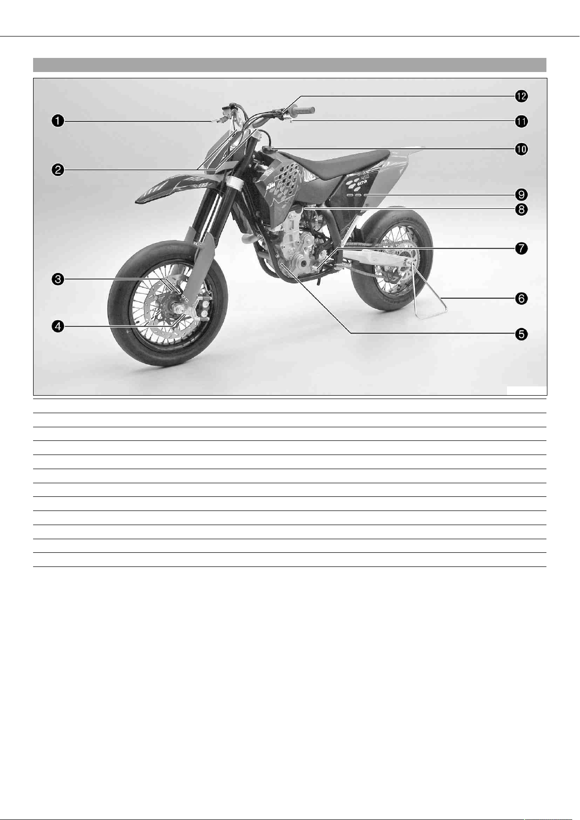
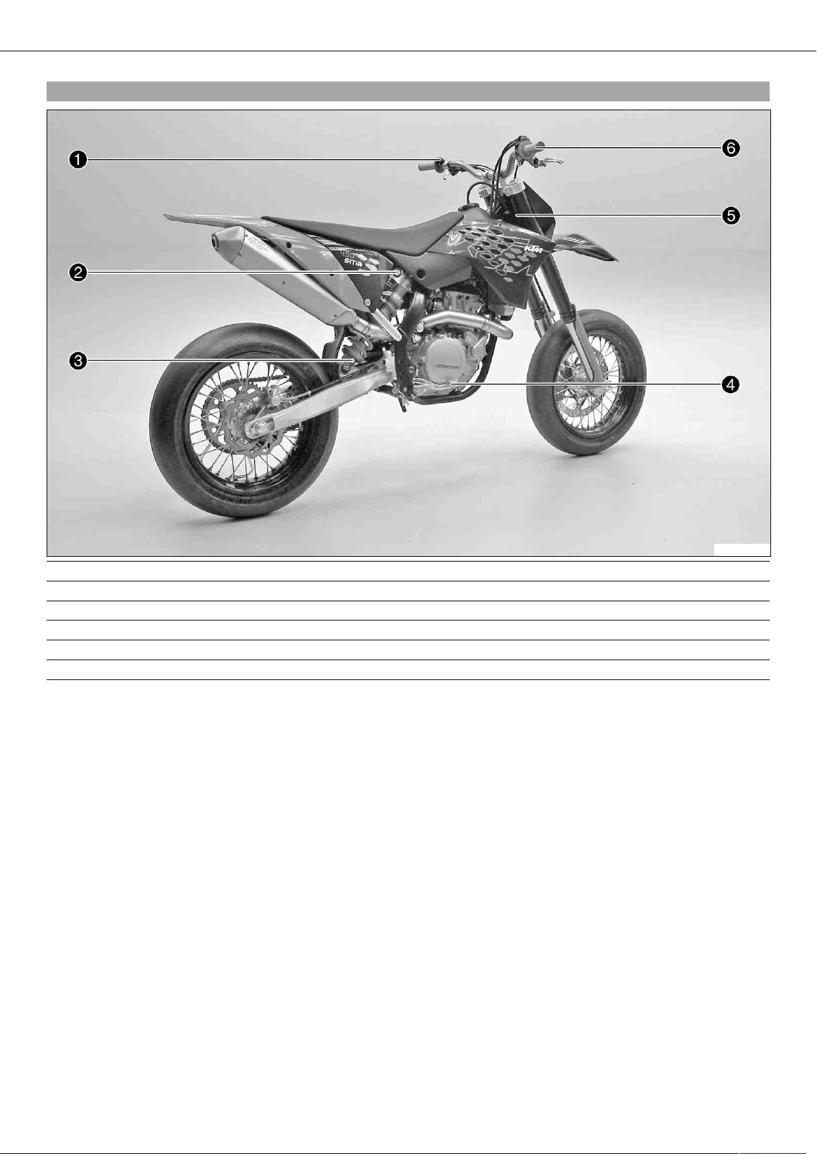
VIEW OF VEHICLE............................................................... 7
View of vehicle, front left side........................................... 7
View of vehicle, rear right side .......................................... 8
LOCATION OF SERIAL NUMBERS ........................................ 9
Chassis number............................................................... 9
Type label....................................................................... 9
Engine number................................................................ 9
Fork part number............................................................. 9
Shock absorber part number............................................. 9
CONTROLS....................................................................... 10
Clutch lever .................................................................. 10
Hot start lever ............................................................... 10
Hand brake lever ........................................................... 10
Short circuit button ....................................................... 10
Electric starter button .................................................... 10
Fuel tap........................................................................ 11
Opening filler cap.......................................................... 11
Closing filler cap ........................................................... 11
Choke........................................................................... 11
Shift lever..................................................................... 12
Foot brake pedal ........................................................... 12
Plug-in stand ................................................................ 12
GENERAL TIPS AND HINTS ON PUTTING INTO
OPERATION...................................................................... 13
Advice on first use......................................................... 13
Running in the engine.................................................... 14
RIDING INSTRUCTIONS .................................................... 15
Checks before putting into operation ............................... 15
Starting ........................................................................ 15
Starting up ................................................................... 16
Shifting, riding.............................................................. 16
Braking ........................................................................ 16
Stopping, parking .......................................................... 16
Refueling...................................................................... 17
SERVICE SCHEDULE......................................................... 18
Important maintenance work to be carried out by an
authorized KTM workshop. ............................................. 18
Important maintenance work to be carried out by an
authorized KTM workshop. (as additional order)................ 19
Important checks and maintenance work to be carried
out by the rider. ............................................................ 19
MAINTENANCE WORK ON CHASSIS AND ENGINE.............. 21
Jacking up the motorcycle.............................................. 21
Removing the motorcycle from the work stand.................. 21
Checking the basic chassis setting with the rider's
weight .......................................................................... 21
Compression damping of shock absorber.......................... 21
Adjusting the high-speed compression damping of the
shock absorber .............................................................. 21
Adjusting the low-speed compression damping of the
shock absorber .............................................................. 22
Adjusting the rebound damping of the shock absorber....... 22
Measuring rear wheel sag unloaded ................................. 23
Checking the static sag of the shock absorber .................. 23
Checking the riding sag of the shock absorber .................. 23
Adjusting the spring preload of the shock absorber x...... 24
Adjusting the riding sag x............................................. 24
Removing the shock absorber x..................................... 25
Installing the shock absorber x..................................... 25
Checking the basic setting of the fork.............................. 25
Adjusting the compression damping of the fork ................ 25
Adjusting the rebound damping of the fork....................... 26
Bleeding fork legs.......................................................... 26
Cleaning dust boots of fork legs ...................................... 27
Removing the fork protector............................................ 27
Installing the fork protector ............................................ 27
Checking play of steering head bearing............................ 27
Adjusting play of steering head bearing x....................... 28
Fork offset .................................................................... 28
Adjusting the fork offset x............................................ 29
Removing the fork legs x.............................................. 29
Installing the fork legs x............................................... 29
Removing the lower triple clamp x................................ 30
Installing the lower triple clamp x................................. 30
Greasing the steering head bearing x............................. 31
Dismounting the front fender.......................................... 31
Installing the front fender............................................... 31
Dismount the start number plate..................................... 32
Installing the start number plate ..................................... 32
Handlebar position ........................................................ 32
Adjusting handlebar position x...................................... 32
Checking gas Bowden cable route ................................... 33
Checking play in the gas Bowden cable ........................... 33
Adjusting the gas Bowden cable play x.......................... 33
Checking for chain dirt accumulation .............................. 34
Cleaning the chain......................................................... 34
Checking the chain tension ............................................ 34
Checking the chain tension when fitting rear wheel........... 35
Checking the rear sprocket / engine sprocket for wear ....... 35
Checking chain wear...................................................... 35
Adjusting the chain tension ............................................ 36
Adjusting chain tension - after checking .......................... 37
Adjusting chain tension - fitting rear wheel ...................... 37
Adjusting chain guide x............................................... 38
Checking the brake discs................................................ 38
Checking the free travel of the hand brake lever ............... 38
Adjusting the basic position of the handbrake lever........... 39
Checking front brake fluid level....................................... 39
Adding front brake fluid x............................................ 39
Checking the front brake linings...................................... 40
Removing front brake linings x..................................... 40
Installing the front brake linings x................................. 41
Changing the front brake linings x................................. 42
Checking free travel of foot brake lever ............................ 42
Adjusting basic position of footbrake lever x................... 43
Checking the rear brake fluid level .................................. 43
Adding brake fluid for the rear brake x.......................... 44
Checking the rear brake linings....................................... 44
Removing rear brake linings x....................................... 45
Installing the rear brake linings x.................................. 45
Changing the rear brake linings x.................................. 46
Removing the front wheel x.......................................... 46
Installing the front wheel x........................................... 47
Removing rear wheel x................................................. 48
Installing the rear wheel x............................................ 48
Checking the tire condition............................................. 49
Checking tire air pressure............................................... 49
Checking spoke tension.................................................. 50
Removing the battery x................................................ 50
Installing the battery x................................................. 50
Recharging the battery x.............................................. 51

CONTENTS 3
Removing a fuse............................................................ 52
Installing the fuse ......................................................... 52
Ignition curve plug connection........................................ 52
Changing the ignition curve ............................................ 52
Removing the seat......................................................... 53
Mounting the seat ......................................................... 53
Removing the fuel tank x............................................. 53
Installing the fuel tank x.............................................. 54
Cooling system .............................................................. 55
Checking antifreeze and coolant level.............................. 55
Checking the coolant level.............................................. 55
Draining the coolant x.................................................. 56
Refilling coolant x....................................................... 56
Removing main silencer ................................................. 57
Installing the main silencer ............................................ 57
Glass fiber yarn filling of main silencer ............................ 57
Removing glass fiber yarn filling of main silencer x......... 57
Installing the glass fiber yarn filling of the main
silencer x................................................................... 58
Changing glass fiber yarn filling of main silencer x......... 58
Dismounting the air filter box lid..................................... 58
Installing the air filter box lid.......................................... 58
Removing the air filter x............................................... 58
Installing the air filter x............................................... 59
Cleaning air filter x...................................................... 59
Adjusting the basic position of the clutch lever................. 59
Antihopping clutch ........................................................ 60
Adjusting the antihopping clutch .................................... 60
Checking the fluid level of hydraulic clutch...................... 61
Changing the hydraulic clutch fluid x............................ 62
Carburetor - idle ............................................................ 62
Carburetor - adjusting idle x......................................... 62
Emptying the carburetor float chamber x....................... 63
Checking engine oil level................................................ 64
Changing engine oil and oil filter, cleaning oil screen x... 64
Draining the engine oil x.............................................. 64
Cleaning the oil screen x.............................................. 65
Removing the oil filter x............................................... 65
Installing the oil filter x............................................... 66
Filling up with engine oil x........................................... 66
Topping up engine oil .................................................... 66
TROUBLESHOOTING......................................................... 67
CLEANING........................................................................ 69
Cleaning motorcycle ...................................................... 69
STORAGE ......................................................................... 70
Storage......................................................................... 70
Putting into operation after storage ................................. 70
TECHNICAL DATA - ENGINE.............................................. 71
Capacity- engine oil ....................................................... 71
Capacity - coolant.......................................................... 71
TECHNICAL DATA - ENGINE TIGHTENING TORQUES.......... 72
TECHNICAL DATA - CARBURETOR..................................... 74
TECHNICAL DATA - CHASSIS ............................................ 75
Capacity - fuel............................................................... 76
TECHNICAL DATA - FORK.................................................. 77
Capacity - fork oil .......................................................... 77
TECHNICAL DATA - SHOCK ABSORBER ............................. 78
TECHNICAL DATA - CHASSIS TIGHTENING TORQUES ........ 79
WIRING DIAGRAM ............................................................ 80
Wiring diagram.............................................................. 80
SUBSTANCES................................................................... 82
AUXILIARY SUBSTANCES.................................................. 84
STANDARDS..................................................................... 86
INDEX .............................................................................. 87

MEANS OF REPRESENTATION 4
Symbols used
The symbols used are explained in the following.
Indicates an expected reaction (e.g. of a work step or a function).
Indicates an unexpected reaction (e.g. of a work step or a function).
All work marked with this symbol requires specialist knowledge and technical understanding. In the interest of
your own safety, have these jobs done in an authorized KTM workshop! There, your motorcycle will be serviced
optimally by specially trained experts using the specialist tools required.
Identifies a page reference (more information is provided on the specified page).
Formats used
The typographical and other formats used are explained in the following.
Specific name Identifies a specific name.
Name®Identifies a protected name.
Brand™ Identifies a brand in merchandise traffic.

IMPORTANT NOTES 5
Use definition
KTM sport motorcycles are designed and built to withstand the normal stresses and strains of competitive use. The motorcycles com-
ply with currently valid regulations and categories of the top international motorsport organizations.
Info
The motorcycle must be used only in closed off areas remote from public road traffic.
Maintenance
A prerequisite for perfect operation and prevention of wear is that the engine and chassis maintenance and adjustment work described
in the owner's manual are properly carried out. Poor adjustment and tuning of the engine and chassis can lead to damage and break-
age of components.
Using the motorcycle in extreme conditions such as very muddy or wet terrain can lead to above-average wear of components such as
the transmission train or the brakes. For this reason, it may be necessary to service or replace worn parts before the limit specified in
the service schedule is reached.
Pay careful attention to the prescribed running-in period, inspection and maintenance intervals. If you observe these exactly, you will
ensure a much longer service life for your motorcycle.
Warranty
The work prescribed in the service schedule must be carried out in an authorized KTM workshop and confirmed in the customer's ser-
vice record, since otherwise no warranty claims will be recognized. No warranty claims can be considered for damage resulting from
manipulations and/or alterations to the vehicle.
Fuel, oils, etc.
You should use the fuels, oils and greases according to specifications as listed in the owner's manual.
Spare parts, accessories
For your own safety, only use spare parts and accessory products that are approved and/or recommended by KTM and have them
installed by an authorized KTM workshop. KTM accepts no liability for other products and any resulting damage or loss.
The current KTM PowerParts for your vehicle can be found on the KTM website.
International KTM Website: http://www.ktm.com
Work rules
When the vehicle is assembled, non-reusable parts (e.g., self-locking screws and nuts, gaskets, seal rings, O-rings, splints, lock wash-
ers) must be replaced with new parts.
Where thread lockers are used on screw connections (e.g., Loctite®), follow the instructions for use from the manufacturer.
After disassembly, clean the parts that are to be reused and check them for damage and wear. Replace damaged or worn parts.
After you complete the repair or maintenance work, check the roadworthiness of the vehicle.
Transport
Note
Danger of damage The parked vehicle can roll away or fall over.
–Always place the vehicle on a firm and even surface.
Note
Fire hazard Some vehicle components get very hot when the machine is driven.
–Do not place the vehicle where there are flammable or explosive substances. Do not place objects over the vehicle while it is still
warm from being run. Always let the vehicle cool first.
–Switch off the engine.
–Turn the handle of the fuel tap to the OFF position. (Figure 500178-10 p. 11)
–Use straps or other suitable devices to secure the motorcycle against accidents or falling over.

IMPORTANT NOTES 6
Environment
Offroad motorcycling is a wonderful sport and we naturally hope that you will be able to enjoy it to the fullest. However, it is a poten-
tial problem for the environment and can lead to conflicts with other persons. But if you use your motorcycle responsibly, you can
ensure that such problems and conflicts do not have to occur. To protect the future of motorcycle sport, make sure that you use your
motorcycle legally, display environmental consciousness, and respect the rights of others.
Notes/warnings
Pay close attention to the notes/warning.
Info
Various information and warning labels are affixed to the vehicle. Do not remove information/warning labels. If they are miss-
ing, you or others may not recognize dangers and may therefore be injured.
Grades of risks
Danger
Identifies a danger that will immediately and invariably lead to fatal or serious permanent injury if the appropriate measures
are not taken.
Warning
Identifies a danger that is likely to lead to fatal or serious injury if the appropriate measures are not taken.
Note
Identifies a danger that will lead to considerable machine and material damage if the appropriate measures are not taken.
Warning
Identifies a danger that will lead to environmental damage if the appropriate measures are not taken.
Owner's manual
–It is important that you read this owner's manual carefully and completely before making your first trip. It contains useful infor-
mation and many tips on how to operate and handle your motorcycle. Only then will you find out how to best customize the motor-
cycle for your own use and how you can protect yourself from injury. The owner's manual also contains important information on
servicing the motorcycle.
–The owner's manual is an important component of the motorcycle and should be handed over to the new owner if the vehicle is
sold.

VIEW OF VEHICLE 7
3.1View of vehicle, front left side
500257-10
1 Hand brake lever
2 Fork compression adjustment
3 Fork part number
4 Fork rebound adjustment
5 Oil filter cover
6 Plug-in stand
7 Shift lever
8 Choke button
9 Air filter
10 Filler cap
11 Clutch lever
12 Hot start lever

VIEW OF VEHICLE 8
3.2View of vehicle, rear right side
500258-10
1 Short circuit button
2 Shock absorber compression adjustment
3 Shock absorber rebound adjustment
4 Foot brake pedal
5 Chassis number/type label
6 Throttle grip

LOCATION OF SERIAL NUMBERS 9
4.1Chassis number
400193-10
The chassis number is stamped on the steering head on the right.
4.2Type label
400284-10
The type label is fixed to the front of the steering head.
4.3Engine number
400194-10
The engine number is stamped on the left side of the engine under the engine
sprocket.
4.4Fork part number
500175-10
The fork part number is stamped on the inner side of the fork stub.
4.5Shock absorber part number
500083-10
The shock absorber part number is stamped on the top of the shock absorber above
the adjusting ring on the engine side.

CONTROLS 10
5.1Clutch lever
500259-10
The clutch lever is fitted on the left side of the handlebar.
The clutch is hydraulically operated and self-adjusting.
5.2Hot start lever
500259-12
The hot start lever is fitted on the left side of the handlebar.
If you pull the hot start lever to the handlebar during the start procedure, a bore is
opened in the carburetor through which the engine can draw in extra air. This gives a
leaner fuel-air mixture, which is needed for a hot start.
Possible states
• Hot start function activated –Hot start lever is pulled out to the stop.
• Hot start function deactivated –Hot start lever is pushed back to the stop.
5.3Hand brake lever
500176-10
Hand brake lever is located on the right side of the handlebar.
The hand brake lever is used to activate the front brake.
5.4Short circuit button
500260-10
Short circuit button is fitted on the left side of the handlebar.
Possible states
• Short circuit button in basic position –In this position, the ignition circuit is
closed, and the engine can be started.
• Short circuit button pressed –In this position, the ignition circuit is interrupted,
a running engine stops, and a non-running engine will not start.
5.5Electric starter button
500177-10
Electric starter button is fitted on the right side of the handlebar.
Possible states
• Electric starter button in basic position
• Electric starter button pressed –In this position, the electric starter is actuated.

CONTROLS 11
5.6Fuel tap
500178-10
With the tap handle on the fuel tap, you can open or close the supply of fuel to the
carburetor.
Possible states
• Fuel supply closed OFF –No fuel can flow from the tank to the carburetor.
• Fuel supply open ON –Fuel can flow from the tank to the carburetor. The fuel tank
empties completely.
5.7Opening filler cap
400199-10
–Press release button , turn filler cap counterclockwise and lift it free.
5.8Closing filler cap
400199-11
–Replace the filler cap and turn clockwise until the release button locks in place.
Info
Run the fuel tank breather hose without kinks.
5.9Choke
500179-10
Choke is fitted on the left side of the carburetor.
Activating the choke function frees an opening through which the engine can draw
extra fuel. This gives a richer fuel-air mixture, which is needed for a cold start.
Info
If the engine is warm, the choke function must be deactivated.
Possible states
• Choke function activated –The choke lever is pulled out to the stop.
• Choke function deactivated –The choke lever is pushed in to the stop.

CONTROLS 12
5.10Shift lever
400204-12
The shift lever is mounted on the left side of the engine.
400204-11
The gear positions can be seen in the photograph.
The neutral or idle position is between the first and second gears.
5.11Foot brake pedal
400205-10
Foot brake pedal is located in front of the right footrest.
The foot brake pedal is used to activate the rear brake.
5.12Plug-in stand
500261-10
Note
Danger of damage The parked vehicle can roll away or fall over.
–Always place the vehicle on a firm and even surface.
To stand the motorcycle, plug the plug-in stand into the left side of the wheel spin-
dle.
Info
Before riding, remove the plug-in stand.

GENERAL TIPS AND HINTS ON PUTTING INTO OPERATION 13
6.1Advice on first use
Danger
Danger of accidents Danger from insufficient traffic competence.
–Do not use the vehicle if you are not fit to deal with traffic or if you have consumed alcohol and/or medicaments or drugs.
Warning
Risk of injury Missing or insufficient protective clothing increases the risk of injury.
–Wear protective clothing (helmet, boots, gloves, pants and jacket with protectors) every time you ride the vehicle. Always
wear protective clothing, which must be in perfect condition and meet legal requirements.
Warning
Danger of accidents Critical riding behavior due to inappropriate riding.
–Adapt your riding speed to the road conditions and your riding ability.
Warning
Danger of accidents Accident risk caused by presence of a passenger.
–Your vehicle is not designed to carry passengers. Do not ride with a passenger.
Warning
Danger of accidents Brake system failure.
–If the foot brake pedal is not released, the brake linings drag permanently. The rear brake can fail due to overheating. Take
your foot off the foot brake pedal if you do not want to brake.
Warning
Danger of accidents Unstable riding behavior.
–Do not exceed the maximum permitted weight and axle loads.
Warning
Risk of misappropriation Usage by unauthorized persons.
–Never leave the vehicle while the engine is running. Secure the vehicle against use by unauthorized persons.
Info
When using your motorcycle, remember that others may feel disturbed by excessive noise.
–Make sure that the pre-delivery inspection work has been carried out by an authorized KTM workshop.
You receive a delivery certificate and the service record at vehicle handover.
–Before your first trip, read the entire operating instructions carefully.
–Get to know the controls.
–Adjust the basic position of the clutch lever. ( p. 59)
–Adjust the basic position of the handbrake lever. ( p. 39)
–Adjust the basic position of the footbrake lever. x( p. 43)
–Become accustomed to the handling of the motorcycle on suitable terrain.
Info
Your motorcycle is not authorized for riding on public roads.
–Try also to ride as slowly as possible and in a standing position to get a better feeling for the vehicle.
–Do not make any trips that over-stress your ability and experience.
–Hold the handlebar firmly with both hands and keep your feet on the footrests when riding.
–Do not transport luggage.
Info
Motorcycles react sensitively to any changes of weight distribution.
–Do not exceed the overall maximum permitted weight and the axle loads.
Guideline
Maximum permissible overall weight 335 kg (739 lb.)
Maximum permissible front axle load 145 kg (320 lb.)
Maximum permissible rear axle load 190 kg (419 lb.)

GENERAL TIPS AND HINTS ON PUTTING INTO OPERATION 14
–Run the engine in.
6.2Running in the engine
–During the running-in phase, do not exceed the specified engine speed and engine performance.
Guideline
Maximum engine speed
During the first 3 service hours 7,000 rpm
Maximum engine performance
During the first 3 service hours ≤50 %
During the next 12 service hours ≤75 %
–Avoid fully opening the throttle!

RIDING INSTRUCTIONS 15
7.1Checks before putting into operation
Info
Make sure that the motorcycle is in a perfect technical condition before use.
Info
In the interests of riding safety, make a habit of making a general check before you ride.
–Check the engine oil level. ( p. 64)
–Check the fuel reserves.
–Check the chain tension. ( p. 34)
–Check for chain dirt accumulation. ( p. 34)
–Check the tire condition. ( p. 49)
–Checking the tire air pressure. ( p. 49)
–Check the front brake brake fluid level. ( p. 39)
–Check the rear brake fluid level. ( p. 43)
–Check the front brake linings. ( p. 40)
–Check the rear brake linings. ( p. 44)
–Check the brake system function.
–Check the coolant level. ( p. 55)
–Check the settings of all controls and ensure that they can be operated smoothly.
7.2Starting
Danger
Danger of poisoning Exhaust gases are poisonous and can result in unconsciousness and/or death.
–When running the engine, always make sure there is sufficient ventilation, and do not start or run the engine in a closed
space without an effective exhaust extraction system.
Note
Engine failure High engine speeds in cold engines have a negative effect on the service life of the engine.
–Always warm up the engine at low engine speeds.
Info
If the motorcycle is unwilling to start, the cause can be old fuel in the float chamber. The flammable elements of the fuel
evaporate after a long time of standing.
If the float chamber is filled with fresh fuel, the engine starts immediately.
Press the starter for a maximum of 5 seconds. Wait for a least 5 seconds until trying again.
Engine has been out of use for more than one week
–Empty the carburetor float chamber. x( p. 63)
–Turn the handle of the fuel tap to the ON position. (Figure 500178-10 p. 11)
Fuel can flow from the fuel tank to the carburetor.
–Remove the motorcycle from the stand.
–Shift gear to neutral.
The engine is cold
–Pull choke lever out as far as possible.
The engine is hot
–Pull the hot start lever out to the stop.
–Press the electric starter button .
Info
Do not open the throttle.
The engine is hot and running
–Push back the hot start lever to the stop with the engine running.

RIDING INSTRUCTIONS 16
7.3Starting up
–Pull the clutch lever, engage 1st gear, release the clutch lever slowly and simultaneously open the throttle carefully.
7.4Shifting, riding
Warning
Danger of accidents If you change down at high engine speed, the rear wheel can lock up.
–Do not change into a low gear at high engine speed. The engine races and the rear wheel can block.
Info
If you hear unusual noises while riding, stop immediately, switch off the engine and contact an authorized KTM workshop.
First gear is used for starting off or for steep inclines.
–When conditions allow (incline, road situation, etc.), you can shift into a higher gear. To do so, release the throttle while simulta-
neously pulling the clutch lever, shift into the next gear, release the clutch and open the throttle.
–If the choke function was activated, deactivate it after the engine has warmed up.
–When you reach maximum speed after fully opening the throttle, turn back the throttle to about ¾ of its range. This barely reduces
vehicle speed but lowers fuel consumption considerably.
–Always open the throttle only as much as the engine can handle –abrupt throttle opening increases fuel consumption.
–To shift down, brake and close the throttle at the same time.
–Pull the clutch lever and shift into a lower gear, release the clutch lever slowly and open the throttle or shift again.
–Switch off the engine if you expect to be standing for a long time.
Guideline
≥2 min
–Avoid frequent and longer slipping of the clutch. This heats the engine oil, the engine and the cooling system.
–Ride with a lower engine speed instead of with a high engine speed and a slipping clutch.
7.5Braking
Warning
Danger of accidents If you brake too hard, the wheels can lock.
–Adapt your braking to the traffic situation and the road conditions.
Warning
Danger of accidents Reduced braking caused by spongy pressure point of front or rear brake.
–Have the brake system checked in an authorized KTM workshop, and do not ride any further.
Warning
Danger of accidents Reduced braking due to wet or dirty brakes.
–Clean or dry dirty or wet brakes by riding and braking gently.
–On sandy, wet or slippery surfaces, use the rear brake.
–Braking should always be completed before you go into a bend. Change down to a lower gear appropriate to your road speed.
–On long downhill stretches, use the braking effect of the engine. Change down one or two gears, but do not overstress the engine.
In this way, you have to brake far less and the brakes do not overheat.
7.6Stopping, parking
Warning
Danger of burns Some vehicle components get very hot when the machine is driven.
–Do not touch hot components such as exhaust system, radiator, engine, shock absorber and brakes. Allow these compo-
nents to cool down before starting work on them.
Note
Danger of damage The parked vehicle can roll away or fall over.
–Always place the vehicle on a firm and even surface.

AA
RIDING INSTRUCTIONS 17
Note
Fire hazard Some vehicle components get very hot when the machine is driven.
–Do not place the vehicle where there are flammable or explosive substances. Do not place objects over the vehicle while it is still
warm from being run. Always let the vehicle cool first.
–Brake the motorcycle.
–Shift gear to neutral.
–Press the Press and hold the short circuit button while the engine is idling until the engine stops.
–Turn the handle of the fuel tap to the OFF position. (Figure 500178-10 p. 11)
–Park the motorcycle on firm ground.
7.7Refueling
Danger
Fire hazard Fuel can easily catch fire.
–Never fill up the vehicle near open flames or burning cigarettes, and always switch off the engine first. Be careful that no
fuel is spilt, especially on hot vehicle components. Clean up spilt fuel immediately.
–Fuel in the fuel tank expands when warm and can escape if the tank is overfilled. See specifications on filling up with fuel.
Warning
Danger of poisoning Fuel is poisonous and a health hazard.
–Avoid contact between fuel and skin, eyes and clothing. Do not inhale fuel vapors. If fuel gets into your eyes, rinse imme-
diately with water and contact a doctor. Wash affected skin areas immediately with soap and water. If fuel is swallowed,
contact a doctor immediately. Change clothing that has come into contact with fuel.
Warning
Environmental hazard Improper handling of fuel is a danger to the environment.
–Do not allow fuel to get into the ground water, the ground, or the sewage system.
–Switch off the engine.
–Open the filler cap. ( p. 11)
400382-10
–Fill the fuel tank with fuel up to measurement .
Guideline
Measurement of 35 mm (1.38 in)
Total fuel tank
capacity, approx.
8.2 l
(2.17 US gal)
Super unleaded (ROZ 95 / RON 95 /
PON 91) ( p. 83)
–Close the filler cap. ( p. 11)

SERVICE SCHEDULE 18
8.1Important maintenance work to be carried out by an authorized KTM workshop.
S3N S10A S30A
Engine Change the engine oil and oil filter, and clean the oil screen. x( p. 64) • • •
Replace spark plug. •
Check and adjust valve clearance. • • •
Check engine mounting screws for tightness. • • •
Clean spark plug connectors and check for tightness. • • •
Check screw of shift lever for tightness. • • •
Carburetor Check carburetor connection boots for cracks and leakage. • •
Check vent hoses for damage and routing without sharp bends. • • •
Check idle. • • •
Attachments Check the cooling system for leakage. • • •
Check the antifreeze and coolant level. ( p. 55) • • •
Check the exhaust system for leakage and looseness. • •
Check Bowden cables for damage, smooth operation and routing without sharp
bends. • • •
Check the fluid level of the hydraulic clutch. ( p. 61) • • •
Clean the air filter. x( p. 59) • • •
Check cables for damage and routing without sharp bends. • •
Brakes Check the front brake linings. ( p. 40) • • •
Check the rear brake linings. ( p. 44) • • •
Check the brake discs. ( p. 38) • • •
Check the front brake brake fluid level. ( p. 39) • • •
Check the rear brake fluid level. ( p. 43) • • •
Check brake lines for damage and leakage. • • •
Check the free travel of the hand brake lever. ( p. 38) • • •
Check the free travel of the foot brake lever. ( p. 42) • • •
Check brake system function. • • •
Check screws and guide bolts of brake system for tightness. • • •
Chassis Check shock absorber and fork for leakage and functioning. • • •
Clean dust boots of fork legs. ( p. 27) • •
Bleed fork legs. ( p. 26) • •
Check swingarm bearing. • •
Check play of steering head bearing. ( p. 27) • • •
Check all screws to see if they are tight. • • •
Wheels Check the spoke tension. ( p. 50) • • •
Check rim run-out. • • •
Check the tire condition. ( p. 49) • • •
Checking the tire air pressure. ( p. 49) • • •
Check the chain wear. ( p. 35) • • •
Check the chain tension. ( p. 34) • • •
Clean the chain. ( p. 34) • • •
Check wheel bearing for play. • • •
Clean and grease adjusting screws of chain adjuster. • • •
S3N: After 3 service hours - corresponds to about 21 liters of fuel
S10A: Every 10 service hours - corresponds to about 70 liters of fuel/after every race
S30A: Every 30 service hours - corresponds to about 210 liters of fuel
Other manuals for 450 SMR
5
Table of contents
Other KTM Motorcycle manuals

KTM
KTM 250 EXC-F EU 2011 Manual

KTM
KTM 1290 Super Duke R 2018 Manual

KTM
KTM RC 390 2020 User manual

KTM
KTM 1190 RC8 User manual

KTM
KTM 250 EXC TPI 2019 Manual

KTM
KTM 125 Duke 2018 User manual

KTM
KTM 250 SX 2019 User manual

KTM
KTM 65 SX 2019 Manual

KTM
KTM 250 EXC-F Six Days 2019 Manual

KTM
KTM 450 XC-F 2018 Manual

KTM
KTM 350 SX-F Cairoli replica User manual

KTM
KTM 400 LS-E/MIL User guide

KTM
KTM 625 SXC Guide

KTM
KTM 690 Duke 2017 User manual

KTM
KTM 250 EXC TPI 2018 User manual

KTM
KTM 500 EXC F 2024 User manual

KTM
KTM 690 DUKE R EU User manual

KTM
KTM 790 Adventure R 2020 Manual

KTM
KTM 690 SMC R 2021 Manual

KTM
KTM 350 SX F 2017 User manual