KTM 2006 660 SMC User manual

KTM-Sportmotorcycle AG
A–5230 Mattighofen
www.ktm.at
KTM Group Partner
7/2005 FOTO: MITTERBAUER
660 SMC
OWNER’S MANUAL 2006
ART. NR. 3.211.77EN
ENGLISH

ENGLISH
1
IMPORTANT »
Please insert the serial numbers of your motorcycle in the boxes below
Frame number
Engine number
Key number
Stamp of dealer
All information contained is without obligation. KTM-Sportmotorcycle AG particularly reserves the right
to modify any equipment, technical specifications, prices, colors, shapes, materials, services, service work,
constructions, equipment and the like so as to adapt them to local conditions or to cancel any of the above
items, all without previous announcement and without giving reasons. KTM may stop manufacturing cer-
tain models without previous notice. KTM shall not be held liable for any deviations of availability and/or
ability to deliver, illustrations, descriptions, printing and/or other errors. The illustrated models partly con-
tain extra equipment, which is not applied to standard models.
© 2004 by KTM-SPORTMOTORCYCLE AG, Mattighofen AUSTRIA; All rights reserved; Reprint, also in
extracts, with written allowance of KTM-SPORTMOTORCYCLE AG, Mattighofen only.
COMSUMER INFORMATION FOR AUSTRALIA ONLY
Tampering with noise control system prohibited
Owners are warned that the law may prohibit:
(a) The removal or rendering inoperative by any person other than for purposes of maintenance, repair or
replacement, of any device or element of design incorporated into any new vehicle for the purpose of
noise control prior to its sale or delivery to the ultimate purchaser or while it is in use; and
(b) the use of the vehicle after such device or element of design has been removed or rendered inopera-
tive by any person.
We strongly suggest that you read this manual carefully and completely before going on your first ride.
It contains a great deal of information and advice which will help you use and handle your bike properly.
In your own interest, please pay particular attention to notices that are marked as follows:
– IGNORING THESE INSTRUCTIONS, CAN ENDANGER YOUR BODY AND YOUR LIFE.
– IGNORING THESE INSTRUCTIONS COULD CAUSE DAMAGE TO PARTS OF YOUR MOTORCYCLE OR THAT
THE MOTOR-CYCLE IS NOT ROAD-SAFE ANYMORE.

ENGLISH
2
INTRODUCTION »
We would like to congratulate you on your purchase of a KTM motorcycle.
You are now the owner of a state-of-the-art sport motorcycle that guarantees to bring you lots of fun and
enjoyment, provided that you clean and maintain it appropriately. Before you go for your first ride, be sure
to read this manual carefully and thoroughly in order to familiarize yourself with how to operate your new
motorcycle and with its characteristics, even if this means that you will have to dedicate some of your
valuable time to this task. Only by doing so will you learn how to tune your motorcycle to your specific
needs and how to protect yourself against injury. Besides, this manual contains important information on
motorcycle maintenance. At the time this manual was typeset, it was up-to-date with the latest state of
this production series. It cannot be completely ruled out, however, that minor discrepancies may exist
resulting from further design upgrades of these motorcycles.This manual is an important part of your motor-
cycle and should be passed on to any subsequent owner in case you decide to sell it.
We expressly point out that work marked with an asterisk in the chapter "Maintenance work on the chas-
sis and engine" must be performed. If maintenance work should become necessary during a competition
it should be performed by a trained mechanic. KTM strongly recommends that all service work to your
KTM should be performed by a qualified KTM dealer.
For your own safety, use KTM-approved parts and accessories only. KTM is not liable for damage that
arises in connection with the use of other products.
Take special care to follow the recommended run in, inspection, and maintenance intervals. Heeding
these guidelines will significantly increase the life of your motorcycle. To ensure that all work to your KTM
is performed properly and to avoid warranty conflicts, KTM recommends that you always have your KTM
serviced by a recognized and qualified KTM dealer.
Motorcycle driving is a wonderful sport and we hope that you will be able to enjoy it to the full. It may,
however, involve potential problems for the environment or lead to conflicts with others. These problems
or conflicts can be avoided if the motorcycle is used responsibly. To safeguard the future of motorcycle
sports, make sure that you use the motorcycle in accordance with the law, show that you are environmen-
tally conscious and respect the rights of others.
We wish you a lot of fun when driving !
KTM-SPORTMOTORCYCLE AG
5230 MATTIGHOFEN, AUSTRIA
Attachments: Spare parts manual chassis & engine

ENGLISH
3
IMPORTANT LIMITED WARRANTY AND LIMITED GUARANTEE INFORMATION
»
The KTM 660 SMC is designed and constructed to resist the usual wear and tear of normal use in
competitions.
The motorcycles comply with the regulations and categories currently in effect with the leading interna-
tional motorcycle associations.
The service, care and operating instructions for the engine and chassis specified in the owner's manual
must be observed to ensure that the bike runs smoothly and to avoid premature wear. An improperly tuned
chassis can lead to damage and breakage of the chassis components.
The service work specified in the "Lubrication and Maintenance Schedule" must be performed and serv-
ice records must be kept for warranty documentation. Lack of proper service and maintenance records or
documentation could void warranty.
The fuels and lubricants specified in the owner's manual or those of an equal quality must be used in
accordance with the maintenance schedule.
The warranty or guarantee shall become void for damage and consequential damage caused by manipu-
lations or conversions to the motorcycle.
The use of the motorcycle under extreme conditions, e.g. on extremely muddy and wet terrain, can lead
to higher than average wear on components such as the drive train or the brakes. In this case it may become
necessary to service or replace wear parts before the service limit specified in the maintenance schedule
has been reached.
The SMC models are only allowed on public roads in the original homologated (throttled) version. Without
this performance restriction (i.e. dethrottled), these models are only allowed to be driven in Supermoto
competitions but not on public roads.
No warranty will be assumed if the bike is used in races or competitions.
In accordance with the international quality management ISO 9001 standard, KTM uses
quality assurance processes that lead to the highest possible product quality.

ENGLISH
4
INDEX »
Page
SERIAL NUMBER LOCATIONS . . . . . . . . . . . . . . . . . . .5
Chassis number . . . . . . . . . . . . . . . . . . . . . . . . . . .5
Engine number, Engine type . . . . . . . . . . . . . . . . . .5
OPERATION INSTRUMENTS . . . . . . . . . . . . . . . . . . . . .5
Clutch lever . . . . . . . . . . . . . . . . . . . . . . . . . . . . . .5
Hand decompression lever . . . . . . . . . . . . . . . . . . . .5
Hand brake lever . . . . . . . . . . . . . . . . . . . . . . . . . . .5
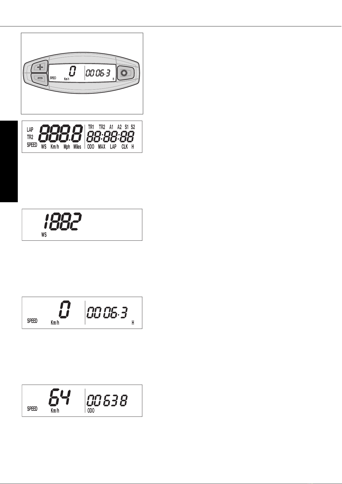
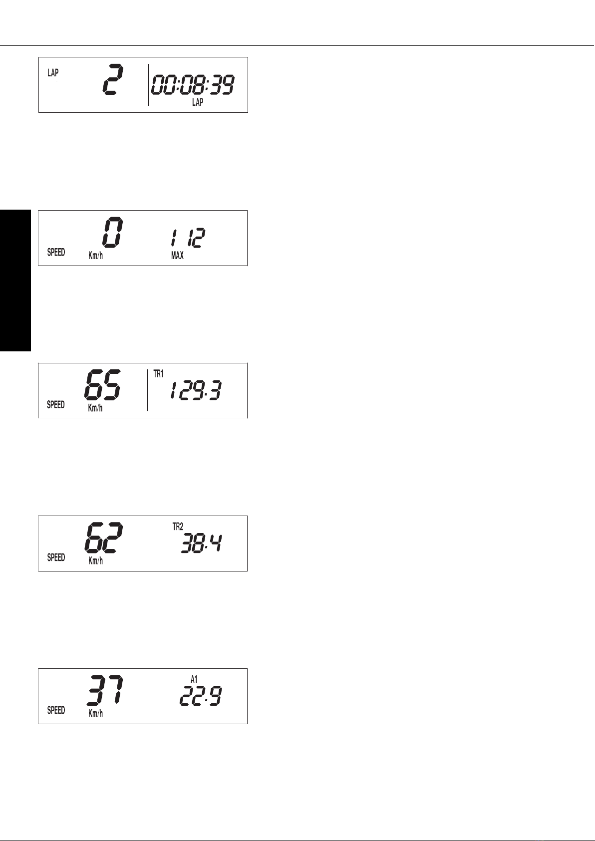
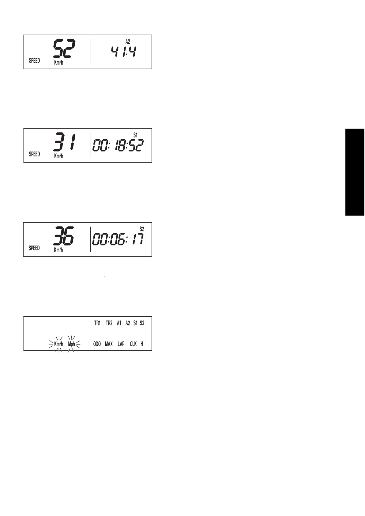
Electronic speedometer . . . . . . . . . . . . . . . . . . . . . .6
Indicator lamps . . . . . . . . . . . . . . . . . . . . . . . . . . .10
Combination switch . . . . . . . . . . . . . . . . . . . . . . . .11
Flasher switch . . . . . . . . . . . . . . . . . . . . . . . . . . .11
Emergency OFF switch (Australia) . . . . . . . . . . . . .11
Filler cap . . . . . . . . . . . . . . . . . . . . . . . . . . . . . . .11
Fuel tap . . . . . . . . . . . . . . . . . . . . . . . . . . . . . . . .11
Choke . . . . . . . . . . . . . . . . . . . . . . . . . . . . . . . . .12
Hot start device . . . . . . . . . . . . . . . . . . . . . . . . . .12
Shift lever . . . . . . . . . . . . . . . . . . . . . . . . . . . . . .12
Kickstarter . . . . . . . . . . . . . . . . . . . . . . . . . . . . . .12
Foot brake pedal . . . . . . . . . . . . . . . . . . . . . . . . . .12
Handlebar lock . . . . . . . . . . . . . . . . . . . . . . . . . .13
Compression damping of fork . . . . . . . . . . . . . . . . .13
Rebound damping of fork . . . . . . . . . . . . . . . . . . .13
Compression damping of shock absorber . . . . . . . . .13
Rebound damping of shock absorber . . . . . . . . . . .13
GENERAL TIPS AND WARNINGS FOR STARTING
THE MOTORCYCLE . . . . . . . . . . . . . . . . . . . . . . . . . .14
Instructions for initial operation . . . . . . . . . . . . . . .14
Running in the LC4 models . . . . . . . . . . . . . . . . . .14
Accessories and payload . . . . . . . . . . . . . . . . . . . .14
DRIVING INSTRUCTIONS . . . . . . . . . . . . . . . . . . . . . .15
Check the following before each start . . . . . . . . . . .15
Starting when the engine is cold . . . . . . . . . . . . . .16
Starting when the engine is warm or hot . . . . . . . . .16
What to do when the engine is “flooded” . . . . . . . .16
Starting off . . . . . . . . . . . . . . . . . . . . . . . . . . . . . .16
Shifting/Riding . . . . . . . . . . . . . . . . . . . . . . . . . . .17
Braking . . . . . . . . . . . . . . . . . . . . . . . . . . . . . . . .17
Stopping and parking . . . . . . . . . . . . . . . . . . . . . .17
Fuel . . . . . . . . . . . . . . . . . . . . . . . . . . . . . . . . . . .18
PERIODIC MAINTENANCE SCHEDULE . . . . . . . . . . . .19
MAINTENANCE WORK ON CHASSIS AND ENGINE . . .21
Removal of seat . . . . . . . . . . . . . . . . . . . . . . . . . .21
Tool set . . . . . . . . . . . . . . . . . . . . . . . . . . . . . . . . .21
Check and adjust steering head bearing . . . . . . . . . .22
Breather plug front fork . . . . . . . . . . . . . . . . . . . . .22
Cleaning the dust sleeves of the telescopic fork . . . .22
Basic suspension setup for the weight of the driver . .23
Changing the spring preloading of the shock absorber
. .24
Checking rubber ring on the WP rear shock absorber
. .25
Lubricate rear suspension linkage . . . . . . . . . . . . . .25
Checking chain tension . . . . . . . . . . . . . . . . . . . . .25
Page
Correct chain tension . . . . . . . . . . . . . . . . . . . . . .26
Chain maintenance . . . . . . . . . . . . . . . . . . . . . . . .26
Chain wear . . . . . . . . . . . . . . . . . . . . . . . . . . . . . .26
General information about KTM disc brakes . . . . . .27
Changing the basic position of the handbrake lever . .28
Checking of brake fluid level - front brake . . . . . . . .28
Refilling the front brake fluid reservoir . . . . . . . . . .28
Checking the front brake pads . . . . . . . . . . . . . . . .28
Replacing the front brake pads . . . . . . . . . . . . . . . .29
Check the rear brake fluid level . . . . . . . . . . . . . . .29
Refilling the rear brake fluid reservoir . . . . . . . . . . .29
Changing the basic position of the brake pedal . . . .30
Checking the rear brake pads . . . . . . . . . . . . . . . . .30
Replacing the rear brake pads . . . . . . . . . . . . . . . .30
Dismounting and mounting the front wheel . . . . . . .31
Dismounting and mounting the rear wheel . . . . . . .31
Tires, air pressure . . . . . . . . . . . . . . . . . . . . . . . . .32
Checking spoke tension . . . . . . . . . . . . . . . . . . . . .32
Checking the shock absorption rubbers in the rear hub
. .32
Check/set distance of the magnetic sensor . . . . . . .33
Replacing the battery in the electronic speedometer
. .33
Replacing the fan fuse . . . . . . . . . . . . . . . . . . . . .33
Replacing headlight lamp/parking light lamp . . . . . .34
Exchanging the brake light and tail light bulb . . . . .34
Cooling system . . . . . . . . . . . . . . . . . . . . . . . . . . .35
Checking the coolant level . . . . . . . . . . . . . . . . . . .35
Cleaning of air filter . . . . . . . . . . . . . . . . . . . . . . .36
Exhaust system . . . . . . . . . . . . . . . . . . . . . . . . . . .36
Adjusting the throttle cable . . . . . . . . . . . . . . . . . .37
Checking the adjustment of the hand decompression cable
. .37
Changing the original position of the clutch lever . . .37
Checking the oil level of the hydraulic clutch . . . . .38
Bleeding of the hydraulic clutch . . . . . . . . . . . . . . .38
Draining the float chamber of the carburetor . . . . . .38
Carburator – Adjust idling . . . . . . . . . . . . . . . . . . . .39
Adjusting the mixture control screw . . . . . . . . . . . . .39
Checking the float level (float height) . . . . . . . . . . . .39
Engine oil . . . . . . . . . . . . . . . . . . . . . . . . . . . . . . .40
Checking the engine oil level . . . . . . . . . . . . . . . . .40
Oil circuit . . . . . . . . . . . . . . . . . . . . . . . . . . . . . . .40
Oil, oil filter and screen filter change,
bleeding of the oil system . . . . . . . . . . . . . . . . . . .41
TROUBLE SHOOTING . . . . . . . . . . . . . . . . . . . . . . . .43
CLEANING . . . . . . . . . . . . . . . . . . . . . . . . . . . . . . . .45
CONSERVATION FOR WINTER OPERATION . . . . . . . . .45
STORAGE . . . . . . . . . . . . . . . . . . . . . . . . . . . . . . . . .45
RE-INITIATION AFTER TIME OF STORAGE . . . . . . . . .45
TECHNICAL SPECIFICATIONS – ENGINE . . . . . . . . . .46
TECHNICAL SPECIFICATIONS – CHASSIS . . . . . . . . .47
HEAD WORD INDEX . . . . . . . . . . . . . . . . . . . . . . . . . .49
WIRING DIAGRAMME . . . . . . . . . . . . . . . . . . .APPENDIX

ENGLISH
5
SERIAL NUMBER LOCATIONS »
Chassis number
The chassis number is stamped on the right side of the steering head tube.
Write this number into the relevant area on page 1.
Engine number, engine type
The engine number and engine type are stamped on the right hand side of
the engine below the chain sprocket. Write this number into the relevant area
on page 1.
Clutch lever
The clutch lever [1] is located on the left side of the handlebar. The adjust-
ing screw [A] is used to change the original position of the clutch lever (see
maintenance work on chassis and engine).
The clutch is hydraulically actuated and adjusts itself automatically.
Hand decompression lever
The hand decompression lever [2] is only used in two special cases:
a) When the engine stalled.
It is possible that the starter motor is not able to crank the engine on the
next attempt. This is due to the fact that the automatic decompressor does-
n’t work properly. If this happens, pull the manual decompression lever
and start again. Afterwards normal starting will be possible.
b) When you want to push the motorcycle.
While pushing, pull the hand decompression lever to make it easier to get
the engine going.
Hand brake lever
The hand brake lever [3] is mounted on the right side of the handlebar.The
basic position of the handbrake lever can be changed in 4 steps
(see Maintenance work on chassis and engine).
OPERATION INSTRUMENTS »
1
2
3
A

ENGLISH
6
OPERATION INSTRUMENTS »
TEST
All of the display segments briefly light up for the display function test.
WS (wheel size)
The display changes and the circumference of the front wheel is briefly dis-
played in millimeters (1882 mm corresponds to a front wheel circumference
of 17" with production tires).
Afterwards the display will return to the previous display mode.
Electronic speedometer
The display in the electronic speedometer is activated as soon as you press
a button on the speedometer or an impulse is received from the wheel sen-
sor. The display lights up when the engine is running.
The display is cleared if no button is pressed for 1 minute or no impulse is
received from the wheel sensor.
The |button is used to change between display modes.
The +and –buttons are used to control various functions.
SPEED display mode / H (service hours)
Only the SPEED / H and SPEED / ODO display modes are activated in the
condition at delivery. SPEED/H is displayed whenever the display is activated
and the front wheel is not turning. It automatically changes to the SPEED/ODO
display mode as soon as the front wheel starts turning.
SPEED displays the speed.
H displays the engine's service hours. The service hour counter starts to count
as soon as you start the engine. The displayed figure cannot be changed.
Service intervals are indicated in service hours for some KTM offroad motor-
cycles, making the service hour counter a very practical function.
SPEED / ODO display mode (odometer)
The SPEED/ODO mode displays the speed and the total distance traveled.
The display automatically changes to the SPEED/H display mode when the
front wheel stops turning.
+button no function
–button no function
briefly press |button changes to the next display mode
hold |button 3 secs. changes to the next display mode
The electronic speedometer has a number of display modes (functions) that
you can also activate (reveal) (see: Activating and deactivating display modes).

ENGLISH
7
OPERATION INSTRUMENTS »
SPEED / LAP (lap time) display mode
You can use the manual stop watch to stop and store up to 10 lap times,
which you can view in the LAP/LAP display mode (see below).
LAP displays the lap times in hours, minutes and seconds.
+button Starts and stops the stop watch, lap time is not
reset to 0
–button Stops the stop watch, stores the lap time and restarts
the stop watch again. The time is reset to 0. A total
of 10 lap times can be stored. If the lap time con-
tinues to run after you press the - button, all 10 mem-
ory locations are occupied.To clear all of the stored
lap times, hold the |button for 3 seconds in the
SPEED/LAP mode.Up to 10 lap times can be stored
in this way.
briefly press |button Changes to the next display mode.If no lap time is
stored or the motorcycle is driving, the LAP/LAP
mode will be skipped.
hold |button 3 secs. Clears all LAP figures
SPEED / CLK (time) display mode
CLK displays the time in hours, minutes and seconds.
+button no function
–button no function
briefly press |button changes to the next display mode
hold |button 3 secs. set the clock menu
To set the clock, see „Setting the clock“.
Activating and deactivating display modes
In the display mode SPEED/H, press and hold the |button for 3 seconds to
access the SETUP menu. The active functions will be displayed. The blink-
ing function can be activated by pressing the +button and deactivated by
pressing the –button.
Press and hold the |button 3 seconds to store the settings.
If no button is pressed for 20 seconds, the setting will be stored automati-
cally and the display will return to the SPEED/H mode.
+button activates the blinking display
–button deactivates the blinking display
briefly press |button changes to the next display without changing any
settings
hold |button 3 secs. starts the SETUP
stores the settings and changes to the SPEED/H
mode
The following display modes can be activated:
TR1 tripmaster 1
TR2 tripmaster 2
A1 average speed 1
A2 average speed 2
S1 stop watch 1
S2 stop watch 2
CLK clock
LAP lap time
MAX maximum speed
KMH/MPH display in kilometers or miles (see: Kilometers or miles)
If you have activated all of the display modes, they will be displayed in the
following order:
SPEED/H, SPEED/CLK, SPEED/LAP, LAP/LAP, SPEED/MAX, SPEED/ODO,
SPEED/TR1, SPEED/TR2, SPEED/A1, SPEED/A2, SPEED/S1, SPEED/S2

ENGLISH
8
OPERATION INSTRUMENTS »
LAP / LAP display mode (to view lap times)
The LAP/LAP display mode will only be shown if lap times have been stored
and the front wheel has stopped. It will display the lap number and the
stopped lap time in hours, minutes and seconds. Press the +button to access
the next lap time.
To clear all of the stored lap times, hold the |button for 3 seconds in the
SPEED/LAP mode.
+button changes to the next lap time
–button no function
briefly press |button changes to the next display mode
hold |button 3 secs. changes to the next display mode
SPEED / MAX display mode (maximum speed)
MAX displays the maximum speed traveled and is always active.
+button no function
–button no function
briefly press |button changes to the next display mode
hold |button 3 secs. clears the MAX figure
SPEED / TR1 display mode (tripmaster 1)
The TR1 tripmaster is always active and counts to 999.9. It is used to meas-
ure the length of a trip or the distance between 2 refueling stops.
TR1 is linked to A1 (average speed 1). The calculation of these figures is acti-
vated by the first impulse received from the wheel sensor (when the front wheel
starts to turn) and stops 3 seconds after the last impulse is received (when
the front wheel has stopped).
The TR1, A1 and S1 figures are automatically cleared after passing 999.9.
+button no function
–button no function
briefly press |button changes to the next display mode
hold |button 3 secs. clears the TR1, S1, A1 figures
SPEED / TR2 display mode (tripmaster 2)
The tripmaster 2 is always active and counts to 999.9. Contrary to TR1, the
displayed figure can be changed using the +and –buttons. This is a very use-
ful function for trips taken according to a roadbook.
+button increases the TR2 figure
–button decreases the TR2 figure
briefly press |button changes to the next display mode
hold |button 3 secs. clears the TR2 figure
SPEED / A1 display mode (average speed 1)
A1 shows the average speed based on the TR1 (tripmaster 1) and S1 (stop
watch 1) figures. The calculation of this figure is activated by the first impulse
received from the wheel sensor and stops 3 seconds after the last impulse is
received.
+button no function
–button no function
briefly press |button changes to the next display mode
hold |button 3 secs. clears the TR1, S1, A1 figures

ENGLISH
9
OPERATION INSTRUMENTS »
Kilometers or miles
The unit (kilometers or miles) can also be changed. The ODO figure will be
retained and converted accordingly. The TR1, A1, S1, TR2 and A2 figures
will be cleared.
To select the unit, select the SPEED/H mode and hold the |button for 3 sec-
onds to access the SETUP menu. Press the |button until the KMH/MPH
function blinks. Press the +button briefly to move to the options. Press the
+button for KMH or the –button for MPH.
To set, briefly press the |button 1 x and hold for 3 seconds until the dis-
play returns to the SPEED/H mode.
If no button is pressed for 20 seconds, the setting will be stored automati-
cally and the display will return to the SPEED/H mode.
+button to access the menu
to activate the KMH display
–button to activate the MPH display
briefly press |button changes to the next mode
changes from the menu to the SETUP menu
hold |button 3 secs. stores and closes the SETUP menu
SPEED / A2 display mode (average speed 2)
A2 shows the average speed based on the TR2 (tripmaster 2) and S2 (stop
watch 2) figures.
The displayed figure can deviate from the actual average speed if the TR2
figure was changed manually or if S2 was not stopped after the trip.
+button no function
–button no function
briefly press |button changes to the next display mode
hold |button 3 secs. changes to the next display mode
SPEED / S1 display mode (stop watch 1)
S1 shows the traveling time based on TR1 and continues to run whenever it
receives impulses from the wheel sensor. The calculation of this figure is acti-
vated by the first impulse received from the wheel sensor and stops 3 sec-
onds after the last impulse is received.
+button no function
–button no function
briefly press |button changes to the next display mode
hold |button 3 secs. clears the TR1, S1, A1 figures
SPEED / S2 display mode (stop watch 2)
S2 is a manual stop watch. Start the stop watch by pressing the +button,
press again to hold. Press again to continue timing.
Press the |button to change to the next mode. The S2 display will blink in
the other modes if S2 continues to run in the background. To stop S2, return
to the SPEED/S2 mode and press the +button.
+button starts and stops the stop watch
–button no function
briefly press |button changes to the next display mode
hold |button 3 secs. clears the S2 figure

ENGLISH
10
OPERATION INSTRUMENTS »
Indicator lamps
The green control lamp [1] flashes when the indicator is working in
the same rhythm as the flashing indicator.
The blue control lamp [2] lights up when the high beam is on.
Setting the clock
To set the clock, switch the ignition off and select the SPEED/CLK mode. Press
and hold the |button for 3 seconds. The blinking digits can be changed
using the +and –buttons. Press the |button to move to the next digit. 0-
12 will show the time in the 12-hour mode, 0-24 in the 24-hour mode.
Press and hold the |button for 3 seconds to store the settings.
If no button is pressed for 20 seconds, the settings will be stored automati-
cally and the display will return to the SPEED/CLK mode.
+button time +
–button time –
briefly press |button changes to the next digit
hold |button 3 secs. starts the SETUP menu
stores the time and changes to the SPEED/CLK dis-
play mode
If the CLK, LAP, MAX, TR1, TR2 A1, A2, S1 and S2 figures are suddenly cleared, the battery in the electronic speedometer is empty
and must be replaced (see: Replacing the battery in the electronic speedometer).
A tripmaster switch is available as an accessory that lets you control the electronic speedometer functions from the handlebar.
Motorcycle is standing
Motorcycle is driving
OVERVIEW OF THE ELECTRONIC SPEEDOMETER FUNCTIONS
display briefly press + button briefly press – button briefly press |button hold |button 3 secs.
XSPEED / H no function no function next display mode
displays the SETUP menu
X X SPEED / CLK no function no function next display mode setting the clock menu
X X SPEED / LAP starts/stops LAP without
clearing LAP figure
stops LAP, stores LAP
figure, resets LAP to 0 next display mode clears all LAP figures
XLAP / LAP next figure no function next display mode next display mode
X X SPEED / MAX no function no function next display mode clears MAX
XSPEED / ODO no function no function next display mode next display mode
X X SPEED / TR1 no function no function next display mode clears TR1, S1, A1
X X SPEED / TR2 increases the TR2 figure reduces the TR2 figure next display mode clears TR2
X X SPEED / A1 no function no function next display mode clears TR1, S1, A1
X X SPEED / A2 no function no function next display mode next display mode
X X SPEED / S1 no function no function next display mode clears TR1, S1, A1
X X SPEED / S2 starts - stops S2 no function next display mode clears S2
1
2

ENGLISH
11
OPERATION INSTRUMENTS »
Combination switch
The light switch has 3 switch positions.
[A] = Light off
[B] = Low beam light
[C] = High beam light
The red short circuit button [1] serves to switch off the engine. Leave the
switch pressed, until the engine stops. With the button [2] the horn will sound.
Flasher switch
The flasher switch is a separate unit and is mounted on the left portion of the
handlebar.
The wire harness is designed in a way that whenever you want to use your
bike in competition, you can dismount the entire turn indicator system with-
out affecting the function of the remaining electrical system.
Flasher left
Flasher right
Emergency OFF switch (Australia)
The emergency OFF switch [3] is located next to the throttle grip. Primarily
designed as safety or emergency OFF switch, it should normally not be in its
activated state.
In this position, the ignition circuit is shorted; if the engine is running,
it will stall immediately, if it is at standstill, it will not start.
In this position, the ignition circuit is enabled; the engine should start.
Filler cap
To open filler cap: Turn the filler cap counter-clockwise.
To close filler cap: Screw on the filler cap clockwise.
Install tank breather hose [4] without kinks.
Fuel tap
OFF In this position the fuel tap is closed. No fuel may flow to the
carburetor.
ON When using the motorcycle, the rotating handle must be set to the ON
position. Now fuel may flow to carburetor. In this position the tank emp-
ties down to the fuel reserve of approx. 2,5 liters.
RES The reserve tank, approximately 2,5 liters, cannot be tapped until the
rotating handle is turned to the RES position. Fill the tank as soon as
possible and remember to turn the rotating handle back to the ON posi-
tion so that you will have backup fuel next time, too.
1 2
A
B
C
3
4

Choke
If you pull the choke button [1] out as far as possible, a bore in the carbure-
tor will be opened through which the engine may take in additional fuel. The
result is a „fat“ fuel-air mixture of the type needed for cold starts.
To deactivate the choke, push the choke button back into its basic position.
Hot start device
If you pull the hot start device [2] out as far as possible, a bore in the carbu-
retor will be opened through which the engine may take in additional air. The
result is a „lean“ fuel-air mixture of the type needed for hot starts.
To deactivate the hot start device, push the hot start button back into its basic
position.
Shift lever
The shift lever is mounted on the left side of the engine. The position of the
gears is shown in the illustration. Neutral position is located between first and
second gear.
Kickstarter
The kickstarter is mounted on the left side of the engine. Its upper part can
be swivelled.
Foot brake pedal
The foot brake pedal is located in front of the right foot rest. Its basic
position can be adjusted to your seat position (see maintenance work).
ENGLISH
12
OPERATION INSTRUMENTS »
1
2
1
2,3,4,5
N

ENGLISH
13
OPERATION INSTRUMENTS »
Handlebar lock
The handlebar can be locked by means of the lock located on the control head.
Fully turn handlebar to right to lock, insert key, turn to left, press in, turn to
right and withdraw.
NEVER LEAVE THE KEY INSERTED IN THE LOCK. IF YOU TURN THE STEERING TO
THE LEFT THE KEY COULD GET DAMAGED.
Compression damping of fork
The compression damping is to be set at the lower end of the fork tubes. It
only regulates the degree of damping during compression. Remove closing
cap [A]. By using the knob [1] (COM), the degree of damping of the compres-
sion can be adjusted. Turn the knob clockwise to increase damping, turn it
counterclockwise to reduce damping during compression.
STANDARD ADJUSTMENT:
Turn adjusting screw clockwise as far as it will go
Turn it back by as many clicks as are specified for the relevant type of fork
WP 14187B07 . . . . 23 clicks
Rebound damping of fork
Hydraulic rebound damping determines the reaction when the fork is rebound.
By turning the knob [2], the degree of damping of the rebound can be adjusted.
Turn the knob clockwise to increase damping, turn it counterclockwise to reduce
damping during rebounding.
STANDARD ADJUSTMENT:
Turn adjusting screw clockwise as far as it will go
Turn it back by as many clicks as are specified for the relevant type of fork
WP 14187B07 . . . . 19 clicks
Compression damping of shock absorber
With the knob [3] the degree of damping of the compression can be adjusted.
Turn the knob counterclockwise to increase damping, turn it clockwise to reduce
damping during rebounding.
STANDARD ADJUSTMENT:
WP 01187B02 . . . . position 4
Rebound damping of shock absorber
With the setting wheel [4] the degree of damping of the rebound can be adjusted.
Turn the knob to the left side to increase damping, turn it to the right side to
reduce damping during rebounding.
STANDARD ADJUSTMENT:
WP 01187B02 . . . . position 8
1
A
2
2
3
4

ENGLISH
14
GENERAL TIPS AND WARNINGS FOR STARTING THE MOTORCYCLE »
Instructions for initial operation
– Verify that your KTM dealer performed the PREPARATION OF
VEHICLE jobs (see Customer Service Manual).
– Read these operating instructions carefully before your first ride.
– Enter the chassis, engine and key numbers on page 1.
– Familiarize yourself with the operating elements.
– Adjust the hand brake lever and foot brake lever to your most
comfortable position.
– Get used to handling the motorcycle on an empty parking lot
or open space, before starting on a longer drive. Also try to drive
as slowly as possible and in standing position, to improve your
feeling for the vehicle.
– Do not drive along off-road tracks which go beyond your abitily
and experience.
– Hold the handlebars with both hands and leave your feet on
the foot rests while driving.
– Remove your foot from the foot brake lever when you are not
braking. If the foot brake lever is not released the brake pads
rub continuously and the braking system is overheated.
– Do not make any alterations to the motorcycle and always use
ORIGINAL KTM SPARE PARTS. Spare parts from other man-
ufacturers can impair the safety of the motorcycle.
– Motorcycles are sensitive to changes in the weight distribution.
Read the section on "Accessories and payload" when carrying
luggage.
– Pay attention to running-in procedure.
Running in the LC4 models
Even very precisely machined sections of engine components have
rougher surfaces than components which have been sliding against
one another for quite some time. Therefore, every engine needs to
be broken in. For this reason, during its first 1000 kilometers (620
miles) the engine must not be revved up to its performance lim-
its. The engine speed of 4800 r.p.m. must not be exceeded dur-
ing the first 1000 kilometers (620 miles). During this break-in time,
you should ride your motorcycle in different conditions (roads,
easy off-road terrain). The following table shows you the maximum
velocity values in the different gears at 4800 r.p.m. as based on
the rear wheel transmission ratio of your motorcycle.
NOTE:
During the stage of running the engine in, that is the first
1000 KM (620 miles), the engine oil used should be of a mineral
oil formula. This also applies if the engine has been repaired.
– WEAR SUITABLE CLOTHING WHEN DRIVING A MOTORCYCLE.
CLEVER KTM DRIVERS ALWAYS WEAR A HELMET, BOOTS, GLOVES
AND A JACKET, REGARDLESS OF WHETHER DRIVING ALL DAY OR
JUST FOR A SHORT TRIP. THE PROTECTIVE CLOTHING SHOULD BE
BRIGHTLY COLORED SO THAT OTHER VEHICLE CAN SEE YOU AS
EARLY AS POSSIBLE.
– DO NOT DRIVE AFTER HAVING CONSUMED ALCOHOL.
– ALWAYS TURN ON THE LIGHT TO MAKE SURE THAT OTHER DRIV-
ERS BECOME AWARE OF YOU AS EARLY AS POSSIBLE.
– DRIVE AT A MODERATE SPEED FOR THE FIRST FEW KILOMETERS
OF EACH TRIP TO ALLOW THE TIRES TO REACH THE NECESSARY
OPERATING TEMPERATURE. MAXIMUM ROAD GRIP IS ASSURED
WHEN THE TIRES ARE WARM.
– THE FRONT AND REAR WHEEL ARE ALLOWED TO BE FITTED ONLY
WITH TIRES THAT HAVE THE SAME PROFILE TYPE.
– NEW WHEELS HAVE A SMOOTH SURFACE, WHICH MEANS THAT THEY
MUST BE RUN IN TO ACHIEVE FULL GRIP. FOR THIS PURPOSE,
RIDE THE MOTORCYCLE CAREFULLY AT MODERATE SPEED DUR-
ING THE FIRST 200 KILOMETERS WITH NEW TIRES, TILTING THE
VEHICLE AT DIFFERENT ANGLES SO THAT ALL SECTIONS ARE
PROPERLY ROUGHENED. TIRES WILL NOT DISPLAY THEIR FULL
GRIP CHARACTERISTICS UNTIL THEY ARE PROPERLY RUN IN.
– OBSERVE THE TRAFFIC REGULATIONS, DRIVE DEFENSIVELY AND
TRYING TO LOOK AHEAD AS FAR AS POSSIBLE SO THAT ANY HAZ-
ARDS CAN BE RECOGNIZED AS EARLY AS POSSIBLE.
– CHOOSE YOUR DRIVING SPEED ACCORDING TO THE CONDITIONS
AND YOUR DRIVING SKILLS.
– DRIVE CAREFULLY ON UNKNOWN ROADS OR ON UNFAMILIAR
TRIALS.
– RENEW THE VIZOR ON YOUR HELMET OR THE GLASS OF YOUR
GOGGLES ON TIME SO AS TO ENSURE OPTIMUM VISION IN ANY
SITUATION. WHEN LIGHT SHINES DIRECTLY ON SCRATCHED VISOR
OR GOGGLES, THE OPERATOR WILL BE BLINDED.
– NEVER LEAVE YOUR MOTORCYCLE WITHOUT SUPERVISION IF THE
ENGINE IS RUNNING.
– WHEN RIDING YOUR MOTORCYCLE, PLEASE BEAR IN MIND THAT
OTHER PEOPLE MAY FEEL MOLESTED BY EXCESSIVE NOISE.
Accessories and payload
Accessory parts and baggage can significantly decrease a motor-
cycle's driving stability. Please observe the following warnings.
– ONLY USE ACCESSORIES THAT HAVE BEEN RELEASED BY KTM. FOR
EXAMPLE, FRONT PANELLING CAN IMPAIR THE DRIVING PROPER-
TIES OF THE MOTORCYCLE. CASES, EXTRA TANKS ETC. CAN ALTER
THE WEIGHT DISTRIBUTION AND THUS ALSO IMPAIR THE VEHI-
CLES DRIVING PROPERTIES.
– FASTEN THE BAGGAGE CLOSE TO THE CENTER OF THE MOTOR-
CYCLE AND DISTRIBUTE THE WEIGHT EVENLY ON THE FRONT AND
REAR WHEELS AND ON THE LEFT AND RIGHT.
– BAGGAGE MUST BE SECURELY AND ADEQUATELY FASTENEND;
LOOSE BAGGAGE WILL SIGNIFICANTLY IMPAIR DRIVING SAFETY.
– A HIGH PAYLOAD WILL CHANGE THE MOTORCYCLE'S HANDLING
AND CONSIDERABLY INCREASE THE BRAKING DISTANCE; ADAPT
YOUR DRIVING SPEED ACCORDINGLY.
– NEVER EXCEED THE MAXIMUM PERMISSIBLE LADEN WEIGHT AND
THE AXLE WEIGHTS. THE MAXIMUM PERMISSIBLE LADEN WEIGHT
IS MADE UP OF THE FOLLOWING COMPONENTS:
– MOTORCYCLE READY FOR OPERATION AND TANK FULL
– LUGGAGE
– DRIVER WITH PROTECTIVE CLOTHING AND HELMET
660 SMC ratio 17:40
1st gear 35 km/h
2nd gear 55 km/h
3rd gear 80 km/h
4th gear 95 km/h
5th gear 110 km/h

ENGLISH
15
DRIVING INSTRUCTIONS »
Check the following before each start
When you start, the motorcycle must be in perfect mechanical condition. For
safety reasons, you should make a habit of performing an overall check of
your motorcycle before each start.
The following checks should be performed:
1 CHECK OIL LEVEL
Insufficient oil results in premature wear and consequently to engine
damage.
2 FUEL
Check that there is sufficient fuel in the tank; when closing the filler cap,
check that the tank venting hose is free of kinks.
3 CHAIN
A loose chain can fall from the chain wheels; an extremely worn chain can
tear, and insufficient lubrication can result in unnecessary wear of chain
and chain wheels.
4 TIRES
Check for damaged tires. Tires showing cuts or dents must be replaced.
The tread depth must comply with the legal regulations. Also check the
air pressure. Insufficient tread and incorrect air pressure deteriorate the
driving performance.
5 BRAKES
Check correct functioning of the braking system. Check for sufficient
brake fluid in the reservoir. The reservoirs have been designed in such a
way that brake fluid does not need to be refilled even when the brake pads
are worn. If the level of brake fluid falls below the minimum value, this
indicates a leak in the braking system or completely worn out brake pads.
Arrange for the braking system to be checked by a KTM specialist, as com-
plete failure of the braking system can be avoided.
Also check the state of the brake hose and the thickness of the brake lin-
ings.
Check free travel at hand brake lever and foot brake lever.
6 CABLES
Check correct setting and smooth operation of all control cables.
7 COOLING FLUID
Check the level of cooling fluid when the engine is cold.
8 ELECTRICAL SYSTEM
Check correct operation of headlamps, tail-lights, brake lights, indicators,
control lamps and horn while the engine is running.
9 LUGGAGE
If you are taking luggage with you, check that this is securely fastened.

ENGLISH
16
DRIVING INSTRUCTIONS »
Starting when the engine is cold
1 Open the fuel tap [1]
2 Swing up the side stand
3 Put the gear in neutral
4 Operate the choke [2]
5 Turn on the emergency OFF switch [4] (Australia only)
6 Go to the left of your motorbike. DO NOT open the throttle, and briskly
kick the kickstarter ALL THE WAY.
– IF YOU WANT TO START THE ENGINE, MAKE SURE THAT YOU ALWAYS PUT ON
STURDY MOTORCYCLE BOOTS IN ORDER TO AVOID INJURIES. YOU MIGHT SLIP
OFF THE KICKSTARTER, OR THE ENGINE MAY KICK BACK AND PUSH YOUR
FOOT UPWARD WITH GREAT VEHEMENCE.
– ALWAYS KICK KICKSTARTER BRISKLY ALL THE WAY WITHOUT OPENING THE
THROTTLE. KICKING THE KICKSTARTER WITH LESS ENOUGH FORCE AND AN
OPENED THROTTLE INCREASE THE KICK-BACK HAZARD.
– CHECK FOR POWER TRANSMISSION AT TEMPERATURES BELOW 0°C (32°F)
BEFORE YOU ACTUATE THE KICKSTARTER. IF YOU DEPRESS THE KICKSTARTER
WITHOUT FEELING ANY RESISTANCE, POWER IS NOT BEING TRANSMITTED.
THIS COULD CAUSE INJURIES.
– DO NOT START THE ENGINE AND ALLOW IT TO IDLE IN A CLOSED AREA.
EXHAUST FUMES ARE POISONOUS AND CAN CAUSE LOSS OF CONSCIOUS-
NESS AND DEATH. ALWAYS PROVIDE ADEQUATE VENTILATION WHILE THE
ENGINE IS RUNNING.
– BEFORE YOU ACTUATE THE KICKSTARTER, BE SURE TO KICK UP THE SIDE
STAND.
– DON’T RIDE YOUR MOTORCYCLE WITH FULL LOAD AND HIGH REVS WHEN
ENGINE IS COLD. BECAUSE THE PISTON IS WARMING UP FASTER THAN THE
WATER COOLED CYLINDER, IT CAN CAUSE ENGINE DAMAGE.
NOTE:
The highly inflammable components in modern fuels volatilize if left stand-
ing for longer periods of time. If the motorcycle has not been used for over
1 week, the fuel should be drained from the float chamber. The engine will
start up immediately if the float chamber is filled with fresh, ignitable fuel
Starting when the engine is warm or hot
1 Open the fuel tap [1]
2 Swing up the side stand
3 Put the gear in neutral
4 Push the hot start button [3]
5 Turn on the emergency OFF switch [4] (Australia only)
6 Go to the left of your motorbike. DO NOT open the throttle, and briskly
kick the kickstarter ALL THE WAY.
What to do when the engine is “flooded”
In the event of a fall, more fuel than necessary may get into the engine. In order
to "pump the engine free", pull the hand decompression lever, fully rev up the
engine, actuate the kickstarter 5 to 10 times. Then, start the engine as described
above. If the engine fails to start, unscrew the spark plug and dry it.
NOTE:
The carburetor has an accelerator pump. Every time you open the throttle,
fuel will be injected into the intake passage. When starting, be sure that you
open the throttle completely only once.
Starting off
Pull the clutch lever. Put the engine into first gear, slowly release the clutch
lever and open throttle at the same time.
1
2
3
4

ENGLISH
17
DRIVING INSTRUCTIONS »
Shifting/Riding
You are now in first gear, refered to as the drive or uphill gear.
Depending on the conditions (traffic, hill size, etc.), you can shift
to a higher gear. Close throttle, at the same time pull clutch lever
in and shift to the next higher gear. Let clutch lever go again and
open throttle. If you turned on the choke, make sure you turn it off
again as soon as engine is warm.
When you reach full speed through opening the throttle all the way,
turn throttle back to 3/4; the speed will not decreases but the engine
will use less fuel.
Only give as much throttle as the engine can handle. Through quick
and high reving of throttle, the fuel consumption increases. When
shifting down, use the brakes if necessary and close throttle at the
same time. Pull clutch lever and shift down to the next gear. Let
clutch lever go slowely and open throttle or shift down again.
– AVOID ABRUPT LOAD CHANGES WHILE RIDING AROUND BENDS
AND ON WET OR SLIPPERY GROUND. OTHERWISE YOU MIGHT
EASILY LOSE CONTROL OF YOUR MOTORCYCLE.
– AFTER FALLING WITH THE MOTORCYCLE, CHECK ALL FUNCTIONS
THOROUGHLY BEFORE STARTING UP OPERATIONS AGAIN.
– A BENT HANDLEBAR MUST ALWAYS BE REPLACED. NEVER TRY TO
STRAIGHTEN THE HANDLEBAR BECAUSE THIS WILL CAUSE IT TO
LOSE ITS STABILITY.
– HIGH RPM RATES WHEN THE ENGINE IS COLD HAVE AN ADVERSE
EFFECT ON THE LIFE OF YOUR ENGINE. WE RECOMMEND YOU RUN
THE ENGINE IN A MODERATE RPM RANGE FOR A FEW MILES TO
WARM UP. AFTER THAT NO FURTHER PRECAUTIONS IN THIS
RESPECT NEED BE TAKEN. THE ENGINE HAS REACHED ITS OPER-
ATING TEMPERATURE AS SOON AS THE RADIATORS BECOME WARM.
– NEVER HAVE THE THROTTLE WIDE OPEN WHEN CHANGING DOWN
TO A LOWER GEAR. THE ENGINE WILL OVER-REV, DAMAGING THE
VALVES. IN ADDITION, THE REAR WHEEL LOCKS SO THAT THE
MOTORCYCLE CAN EASILY GET OUT OF CONTROL.
– LONG WHEELIES LEAD TO A DROP IN THE OIL PRESSURE WHICH
CAN LEAD TO MOTOR DAMAGE.
– IF ANY ABNORMAL VIBRATIONS OCCUR WHILE DRIVING, CHECK
THAT THE ENGINE FASTENING BOLTS ARE TIGHT.
– IN THE EVENT THAT, WHILE RIDING ON YOUR MOTORCYCLE, YOU
NOTICE ANY UNUSUAL OPERATION-RELATED NOISE, STOP
IMMEDIATELY, TURN THE ENGINE OFF, AND CONTACT AN AUTHOR-
IZED KTM DEALER.
Braking
Close throttle and apply the hand and foot brakes at the same time.
Carefully apply the brakes on sandy, wet or slippery surfaces.
Always brake with feeling, blocking wheels can cause you to skid
or fall. Also change down to lower gears depending on your speed.
Always finish braking before you enter a curve.
When driving down hill, use the braking effect of the engine.
Change down one or two gears but do not overspeed the engine.
In this way, you will not need to brake so much and the brakes will
not overheat.
– WHEN YOU BRAKE, THE BRAKE DISCS, BRAKE PADS, BRAKE
CALIPER AND BRAKE FLUID HEAT UP. THE HOTTER THESE PARTS
GET, THE WEAKER THE BREAKING EFFECT. IN EXTREME CASES,
THE ENTIRE BRAKING SYSTEM CAN FAIL.
– IN CASE OF RAIN, AFTER WASHING THE MOTORCYCLE, AFTER
RIDES THROUGH WATER AND IN CASE OF RIDES ON WET OFF-ROAD
TRACKS, HUMID OR DIRTY BRAKE DISCS CAN DELAY THE BRAK-
ING EFFECT. THE BRAKES MUST BE PULLED UNTIL THEY ARE DRY
OR CLEAN.
– RIDES ON SALT-STREWED OR DIRTY ROADS CAN ALSO DELAY THE
BRAKING EFFECT. THE BRAKES MUST BE PULLED UNTIL THEY ARE
CLEAN.
– DIRTY BRAKE DISCS CAUSE INCREASED TEAR OF BRAKE PADS AND
BRAKE DISCS.
– IF THE RESISTANCE IN THE HAND BRAKE LEVER OR FOOT BRAKE
PEDAL FEELS “SPONGY” (TOO MUCH PLAY), THIS IS AN INDICA-
TION THAT SOMETHING IS WRONG WITH THE BRAKE SYSTEM. DON’T
RIDE YOUR MOTORCYCLE ANYMORE WITHOUT FIRST HAVING THE
BRAKE SYSTEM LOOKED OVER BY A KTM DEALER.
Stopping and parking
Apply the brakes fully and put the engine into neutral. To stop the
engine, switch off the ignition or pull the short circuit button when
the engine is idling, until the engine stops. Turn the fuel tap to the
OFF position, park on an area with firm ground, and lock the motor-
cycle.
– ALWAYS PARK YOUR MOTORBIKE ON A SOLID AND HORIZONTAL
SURFACE.
– MOTORCYCLE ENGINES PRODUCE A GREAT AMOUNT OF HEAT
WHILE RUNNING. THE ENGINE, EXHAUST PIPE, MUFFLER, BRAKE
ROTORS, AND SHOCK ABSORBERS CAN BECOME VERY HOT. DO
NOT TOUCH ANY OF THESE PARTS AFTER OPERATING THE MOTOR-
CYCLE, AND TAKE CARE TO PARK IT WHERE PEDESTRIANS ARE
NOT LIKELY TO TOUCH IT AND GET BURNED.
– NEVER LEAVE YOUR MOTORCYCLE WITHOUT SUPERVISION AS
LONG AS THE ENGINE IS RUNNING.
– CLOSE THE FUEL TAP WHEN LEAVING YOUR VEHICLE. OTHERWISE
THE CARBURETTOR CAN FLOOD AND FUEL WILL ENTER THE
ENGINE.
– NEVER PARK YOUR MOTORCYCLE IN FIRE HAZARDOUS PLACES DUE
TO DRY GRASS OR OTHER EASILY FLAMMABLE MATERIALS.
INFORMATION ABOUT THE SIDE STAND:
Use your foot to push the side stand forward as far as possible,
and lean your motorcycle to the side. Make sure that your motor-
cycle is standing safely on solid ground. Just in case, you can also
put in a gear.
– PARK YOUR MOTORCYCLE, SO THAT IT RESTS STABLY ON THE SIDE-
STAND (HARD GROUND, LEVEL SURFACE) AND CAN'T TIP OVER.
– THE SIDE STAND IS DIMENSIONED FOR THE WEIGHT OF THE
MOTORCYCLE ONLY. IF YOU ARE SITTING ON THE MOTORBIKE
AND THUS APPLY AN ADDITIONAL LOAD ONTO THE SIDE STAND,
YOU MAY CAUSE DAMAGE TO THE SIDE STAND OR THE FRAME,
AND YOUR MOTORBIKE MAY FALL OVER.

ENGLISH
18
DRIVING INSTRUCTIONS »
35 mm
Fuel
The LC4 engine needs premium gasoline with an octane number of 95 (ROZ)
or higher (USA = Premium RON 91).
USE LEADED OR UNLEADED PREMIUM GRADE GASOLINE (95 OCTANES). NEVER
USE ANY GASOLINE HAVING LESS THAN 95 OCTANES BECAUSE IT MAY DAMAGE
THE ENGINE.
GASOLINE IS HIGHLY FLAMMABLE AND POISONOUS. EXTREME CAUTION SHOULD
BE USED WHEN HANDLING GASOLINE. DO NOT REFUEL THE MOTORCYCLE NEAR
OPEN FLAMES OR BURNING CIGARETTES. ALWAYS SWITCH OFF THE ENGINE
BEFORE REFUELLING. BE CAREFUL NOT TO SPILL GASOLINE ON THE ENGINE OR
EXHAUST PIPE WHILE THE ENGINE IS HOT. WIPE UP SPILLS PROMPTLY. IF GASO-
LINE IS SWALLOWED OR SPLASHED IN THE EYES, SEEK A DOCTOR’S ADVICE
IMMEDIATELY.
Fuel expands when its temperature rises. Therefore do not fill the tank to the
top (see fig.).

ENGLISH
19
A WASHED MOTORCYCLE CAN BE CHECKED MORE QUICKLY WHICH SAVES MONEY!
1st Service
after 1000 km
or 10 hours
after / every
5000 km
or once a year
ENGINE
Change engine oil, oil filter and fine filter z z
Clean oil screens and magnet of drain plug z z
Check oil lines for damage and kink-less arrangement z z
Check and adjust spark plug, replace it every 10,000 km z
Check and adjust valve clearance z z
Check engine fastening screws for tight fit z z
Make sure all engine screws accessible from the outside are screwed tight z z
CARBURETOR
Check carburetor connection boots for cracks and leaks z
Check idle setting z z
Check bleeder hoses for damage and kink-free arrangement z z
ADD-ON-PARTS
Check cooling system for leaks, antifreeze protection z z
Check radiator fan for proper operation z
Check exhaust system for leaks and suspension z z
Check actuating cables for damage, smooth operation, and kink-less arrangement,adjust and lubricate them
z z
Check fluid level of the clutch master cylinder z z
Clean air filter and air filter box z
Check cables for damage and kink-less arrangement z
Check headlamp adjustment z
Check electrical system for function z z
(low/high beams, stop light, flashers,
indicator lamps, horn, emergency-off switch)
Make sure all screws and nuts are tight z z
BRAKES
Check brake fluid level, lining thickness, and brake discs z z
Check brake lines for damage and leaks z z
Check/adjust smooth operation, free travel of handbrake/footbrake levers z z
Check screws of brake system for tight fit z z
CHASSIS
Check suspension strut and fork for leaks and proper operation z z
Check O-ring of suspension strut for wear z
Clean fork dust sleeves z
Bleed fork legs z z
Check swinging-fork pivot z z
Check/adjust steering-head bearing z z
Lubricate reversing lever z
Check all chassis screws for tight fit (fork plates, fork leg, axle nuts/screws, z z
swinging-fork pivot, reversing lever, suspension strut)
WHEELS
Check spoke tension and rim joint z z
Check tire condition and inflation pressure z z
Check chain and chain guides for wear, force fit and tension. z z
Check screws on pinion and chain sprocket for locking devices and a tight fit z z
Lubricate chain z z
Check wheel bearings and jerk damper for play z
PERIODIC MAINTENANCE SCHEDULE »
660
SMC
2006
IF MOTORCYCLE IS USED FOR COMPETITION 5000 KM SERVICE SHOULD BE CARRIED OUT AFTER EVERY RACE!
SERVICE INTERVALLS SHOULD NEVER BE EXCEED BY MORE THAN 500 KM.
MAINTENANCE WORK DONE BY KTM AUTHORISED WORKSHOPS IS NOT A SUBSTITUTE OF CARE AND CHECKS DONE BY THE
RIDER!
Table of contents
Other KTM Motorcycle manuals

KTM
KTM 85 SX 19 User manual

KTM
KTM 400 SX RACING 2000 User guide

KTM
KTM 350 SX-F 2020 User manual

KTM
KTM 250 SX-F 2021 User manual

KTM
KTM 450 SX-F 2018 User manual

KTM
KTM 1190 RC8 R 2014 Manual

KTM
KTM 400 LS-E/MIL User guide

KTM
KTM 350 EXC-F SIX DAYS EU Operating instructions

KTM
KTM 125 EXE 2001 User guide

KTM
KTM 250 XC TPI 2020 Manual

KTM
KTM 450 Rally Factory Replica User manual

KTM
KTM 350 XCF-W 2022 User manual

KTM
KTM 2011 690 SMC EU Operating instructions

KTM
KTM 1290 SUPER ADVENTURE R 2017 User manual

KTM
KTM LC4 ADVENTURE R 640 2000 User guide

KTM
KTM 125 DUKE EU User manual

KTM
KTM 60 SX 1999 User guide

KTM
KTM 625 SXC Guide

KTM
KTM 1290 Super Duke GT EU 2017 Manual

KTM
KTM 350 EXC-F EU 2015 Manual