KTM 640 LC4 Adventure User manual

KTM-Sportmotorcycle AG
A–5230 Mattighofen
www.ktm.at
KTM Group Partner
09/2005 FOTO: MITTERBAUER
640 LC4 ADVENTURE
OWNER’S MANUAL 2006
ART. NR. 3.211.79 EN
ENGLISH

ENGLISH
1
IMPORTANT »
Please insert the serial numbers of your motorcycle in the boxes below
Frame number
Engine number
Key number
Stamp of dealer
All information contained is without obligation. KTM-Sportmotorcycle AG particularly reserves the right
to modify any equipment, technical specifications, prices, colors, shapes, materials, services, service work,
constructions, equipment and the like so as to adapt them to local conditions or to cancel any of the above
items, all without previous announcement and without giving reasons. KTM may stop manufacturing cer-
tain models without previous notice. KTM shall not be held liable for any deviations of availability and/or
ability to deliver, illustrations, descriptions, printing and/or other errors. The illustrated models partly con-
tain extra equipment, which is not applied to standard models.
© 2005 by KTM-SPORTMOTORCYCLE AG, Mattighofen AUSTRIA; All rights reserved; Reprint, also in
extracts, with written allowance of KTM-SPORTMOTORCYCLE AG, Mattighofen only.
COMSUMER INFORMATION FOR AUSTRALIA ONLY
Tampering with noise control system prohibited
Owners are warned that the law may prohibit:
(a) The removal or rendering inoperative by any person other than for purposes of maintenance, repair or
replacement, of any device or element of design incorporated into any new vehicle for the purpose of
noise control prior to its sale or delivery to the ultimate purchaser or while it is in use; and
(b) the use of the vehicle after such device or element of design has been removed or rendered inopera-
tive by any person.
We strongly suggest that you read this manual carefully and completely before going on your first ride. It
contains a great deal of information and advice which will help you use and handle your bike properly. In
your own interest, please pay particular attention to notices that are marked as follows:
– IGNORING THESE INSTRUCTIONS, CAN ENDANGER YOUR BODY AND YOUR LIFE.
– IGNORING THESE INSTRUCTIONS COULD CAUSE DAMAGE TO PARTS OF YOUR MOTORCYCLE OR THAT
THE MOTOR-CYCLE IS NOT ROAD-SAFE ANYMORE.

ENGLISH
2
INTRODUCTION »
We would like to congratulate you on your purchase of a KTM motorcycle.
You are now the owner of a state-of-the-art sport motorcycle that guarantees to bring you lots of fun and
enjoyment, provided that you clean and maintain it appropriately. Before you go for your first ride, be sure
to read this manual carefully and thoroughly in order to familiarize yourself with how to operate your new
motorcycle and with its characteristics, even if this means that you will have to dedicate some of your
valuable time to this task. Only by doing so will you learn how to tune your motorcycle to your specific
needs and how to protect yourself against injury. Besides, this manual contains important information on
motorcycle maintenance. At the time this manual was typeset, it was up-to-date with the latest state of
this production series. It cannot be completely ruled out, however, that minor discrepancies may exist
resulting from further design upgrades of these motorcycles.This manual is an important part of your motor-
cycle and should be passed on to any subsequent owner in case you decide to sell it.
We expressly point out that work marked with an asterisk in the chapter "Maintenance work on the chas-
sis and engine" must be performed. If maintenance work should become necessary during a competition
it should be performed by a trained mechanic. KTM strongly recommends that all service work to your
KTM should be performed by a qualified KTM dealer.
For your own safety, use KTM-approved parts and accessories only. KTM is not liable for damage that
arises in connection with the use of other products.
Take special care to follow the recommended run in, inspection, and maintenance intervals. Heeding
these guidelines will significantly increase the life of your motorcycle. To ensure that all work to your KTM
is performed properly and to avoid warranty conflicts, KTM recommends that you always have your KTM
serviced by a recognized and qualified KTM dealer.
Off-road motorcycle driving is a wonderful sport and we hope that you will be able to enjoy it to the full.
It may, however, involve potential problems for the environment or lead to conflicts with others. These
problems or conflicts can be avoided if the motorcycle is used responsibly. To safeguard the future of
motorcycle sports, make sure that you use the motorcycle in accordance with the law, show that you are
environmentally conscious and respect the rights of others.
We wish you a lot of fun when driving !
KTM SPORTMOTORCYCLE AG
5230 MATTIGHOFEN, AUSTRIA

ENGLISH
3
IMPORTANT LIMITED WARRANTY AND LIMITED GUARANTEE INFORMATION »
The 640 Adventure is designed and constructed to resist the usual wear and
tear of normal use on the road and easy terrain (dirt roads).
The service, care and operating instructions for the engine and chassis specified in the owner's manual
must be observed to ensure that the bike runs smoothly and to avoid premature wear.
The service work specified in the "Lubrication and Maintenance Schedule" must be performed and serv-
ice records must be kept for warranty documentation. Lack of proper service and maintenance records or
documentation could void warranty.
The fuels and lubricants specified in the owner's manual or those of an equal quality must be used in
accordance with the maintenance schedule.
The warranty or guarantee shall become void for damage and consequential damage caused by manipu-
lations or conversions to the motorcycle.
The use of the motorcycle under extreme conditions, e.g. on extremely muddy and wet terrain, can lead
to higher than average wear on components such as the drive train or the brakes. In this case it may become
necessary to service or replace wear parts before the service limit specified in the maintenance schedule
has been reached.
In accordance with the international quality management ISO 9001 standard, KTM uses
quality assurance processes that lead to the highest possible product quality.

ENGLISH
4
INDEX »
Page
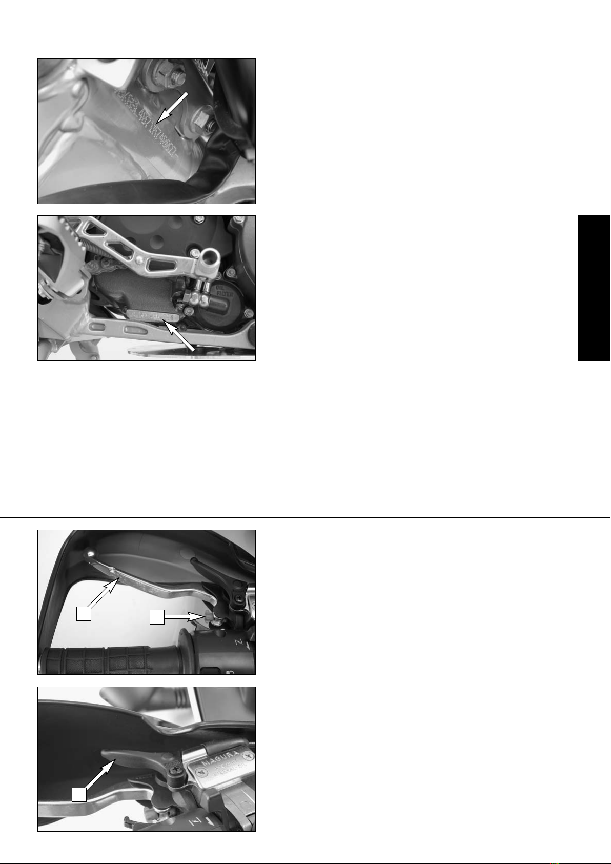
SERIAL NUMBER LOCATIONS . . . . . . . . . . . . . . . . . . . .5
Chassis number . . . . . . . . . . . . . . . . . . . . . . . . . . . .5
Engine number, engine type . . . . . . . . . . . . . . . . . . . .5
OPERATION INSTRUMENTS . . . . . . . . . . . . . . . . . . . . .5
Clutch lever . . . . . . . . . . . . . . . . . . . . . . . . . . . . . . .5
Hand decompression lever . . . . . . . . . . . . . . . . . . . . .5
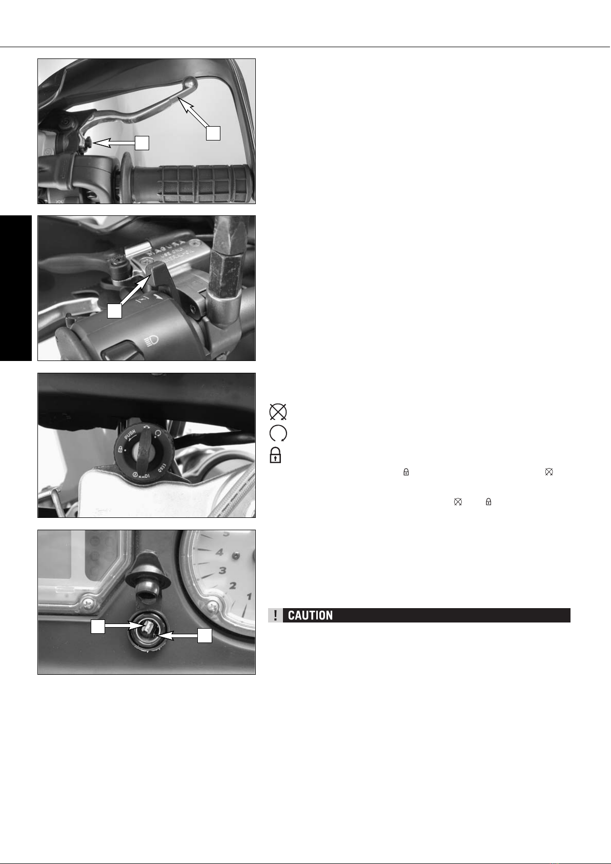
Hand brake lever . . . . . . . . . . . . . . . . . . . . . . . . . . . .6
Choke lever . . . . . . . . . . . . . . . . . . . . . . . . . . . . . . . .6
Ignition lock . . . . . . . . . . . . . . . . . . . . . . . . . . . . . . .6
Socket for electric accessories . . . . . . . . . . . . . . . . . .6
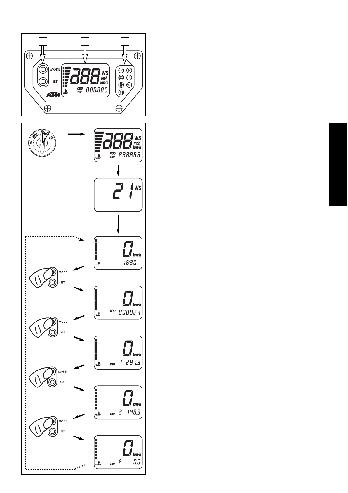
Multi-functional digital speedometer . . . . . . . . . . . . . .7
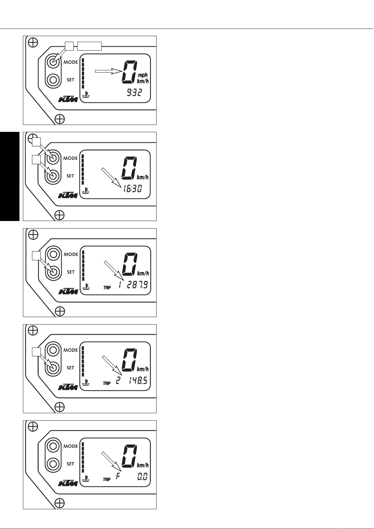
Display . . . . . . . . . . . . . . . . . . . . . . . . . . . . . . . . . . .7
Setting options in the display . . . . . . . . . . . . . . . . . . .8
Cooling liquid temperature display . . . . . . . . . . . . . . .9
Indicator lamps . . . . . . . . . . . . . . . . . . . . . . . . . . . . .9
Tachometer . . . . . . . . . . . . . . . . . . . . . . . . . . . . . . . .9
Combination switch . . . . . . . . . . . . . . . . . . . . . . . . .10
Starter tip switch, emergency OFF tip switch, light switch
. .10
Filler cap . . . . . . . . . . . . . . . . . . . . . . . . . . . . . . . .10
Fuel taps . . . . . . . . . . . . . . . . . . . . . . . . . . . . . . . .10
Shift lever . . . . . . . . . . . . . . . . . . . . . . . . . . . . . . .11
Kickstarter . . . . . . . . . . . . . . . . . . . . . . . . . . . . . . .11
Foot brake pedal . . . . . . . . . . . . . . . . . . . . . . . . . . .11
Compression damping of fork . . . . . . . . . . . . . . . . . .12
Rebound damping of fork . . . . . . . . . . . . . . . . . . . .12
Compression damping of shock absorber . . . . . . . . . .12
Rebound damping of shock absorber . . . . . . . . . . . .12
Baggage carrier / Grips . . . . . . . . . . . . . . . . . . . . . .13
Footrests . . . . . . . . . . . . . . . . . . . . . . . . . . . . . . . .13
GENERAL TIPS AND WARNINGS FOR STARTING
THE MOTORCYCLE . . . . . . . . . . . . . . . . . . . . . . . . . . .14
Instructions for initial operation . . . . . . . . . . . . . . . .14
Running in . . . . . . . . . . . . . . . . . . . . . . . . . . . . . . .14
DRIVING INSTRUCTIONS . . . . . . . . . . . . . . . . . . . . . .15
Check the following before each start . . . . . . . . . . . .15
Starting when the engine is cold . . . . . . . . . . . . . . .16
Starting when the engine is warm or hot . . . . . . . . . .17
What to do when the engine is „flooded” . . . . . . . . .17
Starting the engine with the kickstarter . . . . . . . . . . .17
Starting off . . . . . . . . . . . . . . . . . . . . . . . . . . . . . . .17
Shifting/Riding . . . . . . . . . . . . . . . . . . . . . . . . . . . .17
Braking . . . . . . . . . . . . . . . . . . . . . . . . . . . . . . . . .18
Stopping and parking . . . . . . . . . . . . . . . . . . . . . . .18
Refueling . . . . . . . . . . . . . . . . . . . . . . . . . . . . . . . .19
Activating the ignition curve for low-octane fuel . . . . .19
PERIODIC MAINTENANCE SCHEDULE . . . . . . . . . . . . .20
MAINTENANCE WORK ON CHASSIS AND ENGINE . . . .22
Tool set . . . . . . . . . . . . . . . . . . . . . . . . . . . . . . . . .22
Removing the seat . . . . . . . . . . . . . . . . . . . . . . . . . .22
Checking and adjusting steering head bearing . . . . . .23
Bleeder screw front fork . . . . . . . . . . . . . . . . . . . . . .23
Cleaning the dust sleeves of the telescopic fork . . . . .23
Changing the spring preload of the shock absorber . . .24
Checking rubber ring on the WP rear shock absorber
. .24
Lubricating the shock absorber linkage . . . . . . . . . . .24
Page
Checking chain tension . . . . . . . . . . . . . . . . . . . . . .25
Correct chain tension . . . . . . . . . . . . . . . . . . . . . . . .25
Chain maintenance . . . . . . . . . . . . . . . . . . . . . . . . .26
Chain wear . . . . . . . . . . . . . . . . . . . . . . . . . . . . . . .26
General informations about KTM disc brakes . . . . . . .27
Adjusting of free travel at the hand brake lever . . . . .28
Checking of brake fluid level - front brake . . . . . . . . .28
Refilling the front brake fluid reservoir . . . . . . . . . . .28
Checking the front brake pads . . . . . . . . . . . . . . . . .28
Changing the basic position of the brake pedal . . . . .29
Checking rear brake fluid level . . . . . . . . . . . . . . . . .29
Refilling the rear brake fluid reservoir . . . . . . . . . . . .29
Checking the rear brake pads . . . . . . . . . . . . . . . . .29
Dismounting and mounting the front wheel . . . . . . . .30
Dismounting and mounting the rear wheel . . . . . . . . .31
Checking the shock absorption rubbers in the rear hub
. .31
Tires, air pressure . . . . . . . . . . . . . . . . . . . . . . . . . .32
Checking spoke tension . . . . . . . . . . . . . . . . . . . . . .32
Changing the wheel size . . . . . . . . . . . . . . . . . . . . .32
Battery . . . . . . . . . . . . . . . . . . . . . . . . . . . . . . . . . .33
Charging the battery . . . . . . . . . . . . . . . . . . . . . . . .33
Fuses . . . . . . . . . . . . . . . . . . . . . . . . . . . . . . . . . . .34
Removing and mounting the headlight mask . . . . . . .34
Replacing the headlight bulb . . . . . . . . . . . . . . . . . .34
Exchanging the brake light and tail light bulb . . . . . .35
Removing the tank . . . . . . . . . . . . . . . . . . . . . . . . .35
Cooling system . . . . . . . . . . . . . . . . . . . . . . . . . . . .36
Checking the cooling liquid level . . . . . . . . . . . . . . .36
Cleaning the air filter . . . . . . . . . . . . . . . . . . . . . . . .37
Changing the original position of the clutch lever . . . .38
Checking the oil level of the hydraulic clutch . . . . . .38
Adjusting the throttle cable . . . . . . . . . . . . . . . . . . .38
Checking and adjusting the choke cable play . . . . . . .39
Checking the adjustment of the hand decompression cable
. .39
Adjust idling speed . . . . . . . . . . . . . . . . . . . . . . . . .39
Draining of float chamber of the carburetor . . . . . . . .40
Engine oil . . . . . . . . . . . . . . . . . . . . . . . . . . . . . . . .40
Checking the engine oil level . . . . . . . . . . . . . . . . . .40
Oil circuit . . . . . . . . . . . . . . . . . . . . . . . . . . . . . . . .41
Oil and screen filter change, bleeding of the oil system
. .41
Changing oil filter . . . . . . . . . . . . . . . . . . . . . . . . . .42
TROUBLE SHOOTING . . . . . . . . . . . . . . . . . . . . . . . . .43
CLEANING . . . . . . . . . . . . . . . . . . . . . . . . . . . . . . . . .46
CONSERVATION FOR WINTER OPERATION . . . . . . . . .46
STORAGE . . . . . . . . . . . . . . . . . . . . . . . . . . . . . . . . . .46
RE-INITIATION AFTER TIME OF STORAGE . . . . . . . . . .46
TECHNICAL SPECIFICATIONS – ENGINE . . . . . . . . . . .48
TECHNICAL SPECIFICATIONS – CHASSIS . . . . . . . . . .50
HEAD WORD INDEX . . . . . . . . . . . . . . . . . . . . . . . . . .52
WIRING DIAGRAM . . . . . . . . . . . . . . . . . . . . . .APPENDIX

ENGLISH
5
SERIAL NUMBER LOCATIONS »
OPERATION INSTRUMENTS »
Chassis number
The chassis number is stamped on the right side of the steering head tube.
Write this number into the relevant area on page 1.
Engine number, engine type
The engine number and engine type are stamped on the right hand side of
the engine below the chain sprocket. Write this number into the relevant area
on page 1.
Clutch lever
The clutch lever [1] is fitted on the left hand side of the handle bar.
The adjusting screw [A] is used to change the original position of the clutch
lever (see maintenance work on chassis and engine).
The clutch is hydraulically actuated and adjusts itself automatically.
Hand decompression lever
The hand decompression lever [2] is only used in two special cases:
a) When the engine stalled.
It is possible that the starter motor is not able to crank the engine on the
next attempt. This is due to the fact that the automatic decompressor does-
n’t work properly. If this happens, pull the manual decompression lever
and start again. Afterwards normal starting will be possible.
b) When you want to push the motorcycle.
While pushing, pull the hand decompression lever to make it easier to get
the engine going.
1
2
A

ENGLISH
6
OPERATION INSTRUMENTS »
Hand brake lever
The hand brake lever [1] is mounted on the handlebar on the right and actu-
ates the front wheel brake.The adjusting screw [B] is used to change the orig-
inal position of the hand brake lever (see maintenance work on chassis and
engine).
Choke lever
If the choke lever [2] is pulled backwards, a bore will be opened in the car-
buretor through which the engine may draw in additional fuel. This produces
a „rich“ fuel/air mixture necessary for cold start. If the choke lever is pushed
forward up to the stop, the bore will be closed again. In this position the choke
cable must have a play of approx. 2 mm.
Ignition lock
Switch positions of ignition lock
Ignition off, (engine can't be started)
Ignition on, (engine can be started)
Ignition off, handlebar blocked
To switch the ignition to position turn the ignition key to position and
firmly press it into the lock. Turn the handlebar to the left, then turn the igni-
tion key to the left.
The ignition key can be withdrawn in position and .
Socket for electric accessories
A socket is provided in the cockpit for electric accessories, e.g. GPS, road-
book, cell phone, etc.
The socket has a 12V voltage and is protected by a 5 A fuse. Do not plug
power consumers with a higher requirement into this socket.
You can also use this socket to charge the battery with a maximum of 14.4
volts and 4 amperes.
– REMEMBER THAT ELECTRIC ACCESSORIES WILL RUN DOWN THE BATTERY.
– THE DIGITAL SPEEDOMETER CAN BE DESTROYED IF THE ABOVE CHARGING
LIMITS ARE EXCEEDED.
1
2
B
+–

ENGLISH
7
OPERATION INSTRUMENTS »
Multi-functional digital speedometer
The universal instrument is divided into 3 parts.
Use the MODE and SET [1] button to change the display and the basic set-
tings in the display.
Display [2] shows all of the information that may be of interest to you. 5 dis-
play modes can be selected with the MODE button.
The indicator lamps [3] provide additional information on the motorcycle's
running condition.
Display
TEST
When you switch on the ignition, all of the display elements will light up for
1 second for the function test.
WS (wheel size)
The display will change and show the diameter of the front wheel in inches
for 1 second (WS = wheel size).
Then the CLOCK mode will be displayed, or the mode that was active when
the ignition was switched off.
CLOCK
You will recognize the CLOCK display by the blinking dots between the hours
and minutes. It displays the speed, temperature of the cooling liquid and the
clock.
To switch to the next display mode, press the MODE button.
ODO
The speed, temperature of the cooling liquid and the total kilometers or miles
traveled are shown in the ODO mode.
To switch to the next display mode, press the MODE button.
TRIP 1
The TRIP 1 mode shows the speed, the temperature of the cooling liquid and
the trip odometer 1.
To switch to the next display mode, press the MODE button.
TRIP 2
The TRIP 2 mode shows the speed, the temperature of the cooling liquid and
the trip odometer 2.
To switch to the next display mode, press the MODE button.
TRIP F
The TRIP F (fuel) mode shows the speed, the temperature of the cooling liq-
uid and the distance traveled since reaching the low-fuel mark (the low-fuel
indicator lamp lights up).
To return to the UHR mode, press the MODE button.
TEST
WS
ODO
CLOCK
TRIP 1
TRIP 2
TRIP F
1 2 3

ENGLISH
8
OPERATION INSTRUMENTS »
Setting options in the display
KILOMETERS OR MILES.
You can have the speed and distance shown in kilometers or miles in the dis-
play. The display can be adapted to the respective country on long-distance
trips.
To switch from kilometers to miles, switch on the ignition and press the MODE
[1] button for approx. 10 seconds. The km/h display will switch to mph. The
speed and the stored distances will be converted and displayed in miles.
To return to kilometers, proceed as described above.
CLOCK
Switch on the ignition and change to the CLOCK mode.
Simultaneously press MODE [1] and SET [2]. The numbers on the clock will
start to blink. Use the MODE button to set the hours and the SET button to
set the minutes.
The press the MODE and SET buttons simultaneously.
NOTE:
0:00 will be displayed if the clock is not supplied with electricity. This can
be caused by a defective fuse or a fault in the board electric system (see
Troubleshooting).
TRIP 1
The trip meter 1 runs continuously and counts up to 999.9. It can be used
to measure the length of a certain route on a trip or the distance between two
refueling stops.
To return the trip meter 1 to zero, switch on the ignition, change to the TRIP
1 mode and press the SET button.
RESETTING TRIP 2
The trip meter 2 runs continuously and counts up to 999.9. It can be used
similarly to TRIP 1 or together with a switch available as an accessory (see
below) for trips according to a roadbook.
To return the trip meter 2 to zero, switch on the ignition, change to the TRIP
2 mode and press the SET button.
NOTE:
A Tripmaster switch (Part no. 582.14.069.044) is available as an accessory
and enhances the trip meter 2 functions. You can correct the displayed route
by increasing or decreasing in increments of 0.1. For example, if you have
taken the wrong road when driving according to a roadbook, you can easily
correct the display to correspond to the roadbook again. It can also be used
to change the display modes. The switch is mounted on the handlebars so
that you can keep your hands on the handlebars.
TRIP F
When the fuel level reaches the reserve mark, the display will automatically
switch to TRIP F and begin to count (no matter which display mode was active
before). At the same time, the fuel warning lamp will light up. You will still
have enough reserve fuel for at least 35 kilometers.
After refueling, it will take approx. 8 minutes for the fuel warning lamp to
switch off and for TRIP F to automatically reset to 0 and return to the previ-
ous display mode.
NOTE: Press the SET key for 2 seconds to immediately turn off the fuel warn-
ing lamp.
NOTE: To use up the reserve fuel in the tank, move the fuel cock to the RES
position by hand.
110 sec
1
2
2
2

ENGLISH
9
Cooling liquid temperature display
The temperature display [1] is shown in 7 bars. The more bars that light up,
the hotter the cooling liquid. When the lowest bar lights up, the cooling liq-
uid has reached a temperature of approx. 40°C (104°F). When the upper bar
lights up 120°C (248°F), all of the bars will start to blink and the red warn-
ing lamp [2] will light up.
POSSIBLE CAUSES FOR AN INCREASE IN TEMPERATURE, CAUSING THE RED
WARNING LIGHT FOR THE COOLING LIQUID TEMPERATURE TO LIGHT UP (ALSO
SEE PAGE 36):
– DRIVING TOO SLOWLY AND DRIVING WITH A HEAVY LOAD AT HIGH AIR TEM-
PERATURES
– NOT ENOUGH COOLING LIQUID IN THE SYSTEM
– THE VENTILATOR ON THE LEFT RADIATOR IS NOT RUNNING
– IMPROPER USE OF THE CLUTCH WHEN DRIVING SLOWLY
Indicator lamps
The green indicator lamp will blink in the blinker rhythm when the
blinker is switched on.
NOTE:
The indicator lamp will blink slower when a blinker is broken.
The green indicator lamp will light up when the gearbox is in an
idling position.
The blue indicator lamp will light up when the high beams are
switched on.
The red warning light will light up when the cooling liquid has
reached a temperature of approx. 120°C (248°F).
The orange warning light will light up when the fuel level has
reached the reserve mark. At the same time the display will auto-
matically change to TRIP F (see TRIP F).
This warning light has no function.
This indicator lamp has no function.
Tachometer
The tachometer [3] shows the engine speed in revolutions per minute (rpm).
Do not push the engine into the black zone, which begins at 8500 rpm.
120°C (248°F)
110°C (230°F)
100°C (212°F)
70°C (158°F)
60°C (140°F)
50°C (122°F)
40°C (104°F)
OPERATION INSTRUMENTS »
3
1
2

ENGLISH
10
OPERATION INSTRUMENTS »
Combination switch
The rocker switch LIGHTS [1] actuates the high beam or low beam.
= High-beam light
= Low-beam light
= The light signal (high beam) is actuated with button [2].
The indicator switch [3] returns to central position after actuation. Press
flasher switch towards switch housing to switch off the flasher.
The horn is sounded with button [4].
Starter tip switch, emergency OFF tip switch, light switch
Use the starter tip switch [5] to operate the electric starter.
The light switch has 3 positions:
= Light off
= Parking light on
= Headlight on
The emergency off switch [6] is provided for emergency situations and should
not be used to switch off the engine.
The engine is ready for operation in position (ignition circuit and starter
circuit are switched on).
The engine cannot be started in position (ignition circuit and starter cir-
cuit are interrupted).
Filler cap
The filler cap [7] can be locked and is provided with a fuel evaporation con-
trol system.
To open the cap insert the ignition key, turn it 90° counterclockwise, then lift
off the filler cap.
To close the tank insert the filler cap, turn the ignition key 90° clockwise and
take out the key.
Fuel taps
The motorcycle is equipped with a fuel taps and 2 auxiliary fuel cocks [8].
A fuel pump pumps the fuel from the tank to the carburetor.
The auxiliary fuel cocks on the inside of the tank are connect the two tank
chambers via a line. They must always be open.
Open position: turn the knob to the limit in a counter-clockwise direction.
NOTE:
Only close the two auxiliary fuel cocks when you remove the fuel tank (see
chapter on removing the tank).
1
2
8
8
4
3
1
7
5
6

ENGLISH
11
OPERATION INSTRUMENTS »
Fuel tap [A] on the left side of the tank has 3 positions.
OFF In this position the fuel tap is closed. No fuel can flow to the
carburetor.
ON When using the motorcycle, the twist grip must be set to the ON posi-
tion. Now fuel can flow to fuel pump. In this position the tank empties
down to the fuel reserve of approx. 3,5 liters (0,9 US gallone).
RES The reserve, approximately 3,5 liters (0,9 US gallone), cannot be tapped
until the twist grip is turned to the RES position. Fill the tank as soon
as possible and remember to turn the twist grip back to the ON posi-
tion so that you will have backup fuel next time, too.
NOTE:
The fuel tap must be open during operation. The fuel tap must be closed for
parking.
Shift lever
The shift lever is mounted on the left side of the engine. The position of the
gears is shown in the illustration. Neutral, or the idle speed, is located between
first and second gear.
Kickstarter
The kickstarter is mounted on the left side of the engine. Its upper part can
be swivelled.
Foot brake pedal
The foot brake pedal is located in front of the right footrest. Its basic position
can be adjusted to your seat position (see maintenance work).
N
O
O
F
F
R
E
S
F
U
E
L
N
O
O
F
F
R
E
S
F
U
E
L
N
O
O
F
F
R
E
S
F
U
E
L
OFF ON RES
1
N
2,3,4,5
A

ENGLISH
12
OPERATION INSTRUMENTS »
Compression damping of fork
The compression damping is to be set at the lower end of the fork tubes. It
only regulates the degree of damping during compression.Remove closing cap
[A]. By using the knob [1] (COM), the degree of damping of the compression
can be adjusted. Turn the knob clockwise to increase damping, turn it coun-
terclockwise to reduce damping during compression.
BASIC SETTING
– turn rotary knob clockwise as far as it will go
– turn it back counter-clockwise by as many clicks as are specified for the
relevant type of fork
WP 14187B26 . . . .16 clicks
Rebound damping of fork
The rebound damping is to be set at the upper end of the fork tubes. It only
regulates the degree of damping during rebounding.
By using the knob [2] (REB), the degree of damping of the rebound can be
adjusted. Turn the knob clockwise to increase damping, turn it counterclock-
wise to reduce damping during rebounding.
BASIC SETTING
– turn rotary knob clockwise as far as it will go
– turn it back counter-clockwise by as many clicks as are specified for the
relevant type of fork
WP 14187B26 . . . .12 clicks
Compression damping of shock absorber
With the knob [3] the degree of damping of the compression can be adjusted
to 7 positions. Turn the knob counterclockwise to increase damping, turn it
clockwise to reduce damping during compression.
BASIC SETTING:
WP 01187B04 . . . .position 6
Rebound damping of shock absorber
With the setting wheel [4] the degree of damping of the rebound can be adjusted
to 11 positions. Turn the knob to the left side to increase damping, turn it to
the right side to reduce damping during rebounding.
BASIC SETTING:
WP 01187B04 . . . .position 7
1
A
22
3
4

ENGLISH
13
OPERATION INSTRUMENTS »
Baggage carrier / Grips
The baggage carrier [1] may be loaded with up to 10 kg. The two lateral hoops
[2] serve as handles for the passenger
Footrests
The passenger footrests [3] fold up.
1
2
2
3

ENGLISH
14
GENERAL TIPS AND WARNINGS FOR STARTING THE MOTORCYCLE »
Instructions for initial operation
– Make sure the work for the „pre-delivery inspection“ was per-
formed by your authorized KTM workshop. The DELIVERY CER-
TIFICATE and SERVICE MANUAL will be handed over when you
pick up your vehicle.
– Read the entire manual carefully before your first drive.
– Enter the chassis, engine and key numbers on page 1.
– Familiarize yourself with the operating elements.
– Adjust the foot brake pedal to the most comfortable positions
for you.
– Make the basic settings on the multi-functional digital speedo-
meter.
– Get used to handling the motorcycle on an empty car park, before
starting on a longer drive. Also try to drive as slowly as possi-
ble and in standing position, to improve your feeling for the
vehicle.
– Do not drive along off-road tracks which go beyond your abil-
ity and experience.
– Hold the handlebar with both hands and leave your feet on the
foot rests while driving.
– Remove your foot from the foot brake pedal when you are not
braking. If the foot brake pedal is not released the brake pads
rub continuously and the braking system is overheated.
– You may only be accompanied by a passenger if your motorcy-
cle is fitted and registered for such purposes. The passenger
must hold tight to the brackets or hold on to the driver during
the drive, with his feet on the passenger foot rests.
– Do not make any alterations to the motorcycle and always use
ORIGINAL KTM SPARE PARTS. Spare parts from other man-
ufacturers can impair the safety of the motorcycle.
– New tires have a smooth surface and must be run in. For this
purpose, carefully ride the motorcycle at moderate speed, tilt-
ing the vehicle at different angles so that the surface is evenly
roughened. Tires will not display their full grip characteristics
before they are properly run in.
– Motorcycles are sensitive to changes in the weight distribution.
Read the section on "Accessories and payload" when carrying
luggage.
– Pay attention to running in instructions.
Running in
Even finely machined surfaces of engine parts have rougher sur-
faces than parts that slide on each other for a long time. Therefore,
every engine must be run in. For this reason, do not demand max-
imum performance from the engine for the first 100 kilometers.
The vehicle must be run in at low, changing performance level for
the first 1000 KM (620 miles). The maximum number of revolu-
tions per minute must not go exceed 4800 rpm. Do not acceler-
ate the engine up to the black mark on the tachometer (8500 r.p.m.)
during a running-in period of 1000 km. Exceeding the above listed
rotations as well as pushing high rpm when the engine is cold will
have an adverse effect on the life of your engine.
– WEAR SUITABLE CLOTHING WHEN DRIVING A MOTORCYCLE.
CLEVER KTM DRIVERS ALWAYS WEAR A HELMET, BOOTS, GLOVES
AND A JACKET, REGARDLESS OF WHETHER DRIVING ALL DAY OR
JUST FOR A SHORT TRIP. THE PROTECTIVE CLOTHING SHOULD BE
BRIGHTLY COLOURED SO THAT OTHER USERS OF THE ROADS CAN
SEE YOU AS EARLY AS POSSIBLE. YOUR PASSENGER OF COURSE
WILL ALSO NEED SUITABLE PROTECTIVE CLOTHING.
– ALWAYS TURN ON THE LIGHT MAKE SURE THAT OTHER DRIVERS
BECOME AWARE OF YOU AS EARLY AS POSSIBLE.
– DO NOT DRIVE AFTER HAVING CONSUMED ALCOHOL.
– DRIVE AT A MODERATE SPEED FOR THE FIRST FEW KILOMETERS
OF EACH TRIP TO ALLOW THE TIRES TO REACH THE NECESSARY
OPERATING TEMPERATURE. MAXIMUM ROAD GRIP IS ASSURED
WHEN THE TIRES ARE WARM.
– THE FRONT AND REAR WHEEL ARE ONLY ALLOWED TO BE TIRED
WITH TIRES THAT HAVE THE SAME PROFILE TYPE.
– OBSERVE THE TRAFFIC REGULATIONS, DRIVE DEFENSIVELY AND
TRYING TO LOOK AHEAD AS FAR AS POSSIBLE SO THAT ANY HAZ-
ARDS CAN BE RECOGNIZED AS EARLY AS POSSIBLE.
– ADJUST YOUR DRIVING SPEED ACCORDING TO THE CONDITIONS
AND YOUR DRIVING SKILLS.
– DRIVE CAREFULLY ON UNKNOWN ROADS
– REPLACE THE HELMET VISOR RESPECTIVELY GOGGLE GLASSES
IN PLENTY OF TIME. WHEN LIGHT SHINES DIRECTLY ON SCRATCHED
VISOR OR GOGGLES, YOU WILL BE PRACTICALLY BLIND.
– NEVER LEAVE YOUR MOTORCYCLE WITHOUT SUPERVISION AS
LONG AS THE ENGINE IS RUNNING.
Accessories and payload
Accessory parts and baggage can significantly decrease a motor-
cycle's driving stability. Please observe the following warnings.
– ONLY USE ACCESSORIES THAT HAVE BEEN RELEASED BY KTM. FOR
EXAMPLE, FRONT PANELLING CAN IMPAIR THE DRIVING PROPER-
TIES OF THE MOTORCYCLE. CASES, EXTRA TANKS ETC. CAN ALTER
THE WEIGHT DISTRIBUTION AND THUS ALSO IMPAIR THE VEHI-
CLE’S DRIVING PROPERTIES.
– NEVER DRIVE FASTER THAN 130 KPH (80 MPH) IF YOUR MOTOR-
CYCLE IS LOADED WITH CASES OR OTHER BAGGAGE. THEY WILL
IMPAIR THE MOTORCYCLE'S HANDLING AT HIGHER SPEEDS AND
CAN EASILY CAUSE IT TO GO OUT OF CONTROL
– IF YOU HAVE CASES MOUNTED, DO NOT EXCEED THE MANUFAC-
TURER'S RECOMMENDED MAXIMUM PAYLOAD.
– FASTEN THE BAGGAGE CLOSE TO THE CENTER OF THE MOTOR-
CYCLE AND DISTRIBUTE THE WEIGHT EVENLY ON THE FRONT AND
REAR WHEELS AND ON THE LEFT AND RIGHT.
– BAGGAGE MUST BE SECURELY AND ADEQUATELY FASTENEND;
LOOSE BAGGAGE WILL SIGNIFICANTLY IMPAIR DRIVING SAFETY.
– A HIGH PAYLOAD WILL CHANGE THE MOTORCYCLE'S HANDLING
AND CONSIDERABLY INCREASE THE BRAKING DISTANCE; ADAPT
YOUR DRIVING SPEED ACCORDINGLY.
– NEVER EXCEED THE MAXIMUM PERMISSIBLE LADEN WEIGHT AND
THE AXLE WEIGHTS. THE MAXIMUM PERMISSIBLE LADEN WEIGHT
IS MADE UP OF THE FOLLOWING COMPONENTS:
– MOTORCYCLE READY FOR OPERATION AND TANK FULL
– LUGGAGE
– DRIVER AND PASSENGER WITH PROTECTIVE CLOTHING AND
HELMET.

ENGLISH
15
DRIVING INSTRUCTIONS »
Check the following before each start
When you start off, the motorcycle must be in a perfect technical condition.
For safety reasons, you should make a habit of performing an overall check
of your motorcycle before each start.
The following checks should be performed:
1 CHECK THE OIL LEVEL
Insufficient oil results in premature wear and consequently to engine
damage.
2 FUEL
Check the fuel level in the tank.
3 CHAIN
A loose chain can fall off; an extremely worn chain can tear, and insuffi-
cient lubrication can result in unnecessary wear to the chain and rear sprock-
ets.
4 TIRES
Check for damaged tires. Tires showing cuts or dents must be replaced.
The tread depth must comply with the legal regulations. Also check the
air pressure. Insufficient tread and incorrect air pressure reduce the driv-
ing performance.
5 BRAKES
Check correct functioning of the braking system. Check for sufficient
brake fluid in the reservoir. The reservoirs have been designed in such a
way that brake fluid does not need to be refilled even when the brake pads
are worn. If the level of brake fluid falls below the minimum value, this
indicates a leak in the braking system or completely worn out brake pads.
Arrange for the braking system to be checked by a KTM specialist garage,
as complete failure of the braking system can be expected.
Also check the state of the brake hoses and the thickness of the brake
linings.
Check free travel at hand brake lever and foot brake pedal.
IF THE RESISTANCE IN THE HAND BRAKE LEVER OR FOOT BRAKE PEDAL FEELS
“SPONGY” (TOO MUCH GIVE), THIS IS AN INDICATION THAT SOMETHING IS WRONG
WITH THE BRAKE SYSTEM. DON’T RIDE YOUR MOTORCYCLE ANYMORE WITHOUT
FIRST HAVING THE BRAKE SYSTEM LOOKED OVER BY A KTM DEALER.
6 CABLES
Check correct setting and easy running of all control cables.
7 COOLING LIQUID
Check the level of cooling liquid when the engine is cold.
8 ELECTRICAL SYSTEM
Check headlight, parking light, tail light, brake light, flashers, indicator
lamps and horn for faultless operation.
9 LUGGAGE
If you are taking luggage with you, check that this is securely fastened.

ENGLISH
16
DRIVING INSTRUCTIONS »
Starting when the engine is cold
1 Open the fuel tap.
2 Turn on the ignition (ignition key position: ).
3 Switch the gear to neutral (green lamp [1] lights).
4 Switch on the emergency off switch [2].
5 Operate the choke lever [3].
6 Operate the starter tip switch [4] without accelerating.
7 If the engine starts, push the choke lever back a little bit, as soon as the
engine runs unevenly.
8 Swing up the centerstand
9 Switch on the light before setting off.
DO NOT START THE ENGINE AND ALLOW IT TO IDLE IN A CLOSED ROOM. EXHAUST
FUMES ARE POISONOUS AND CAN CAUSE LOSS OF CONSCIOUSNESS AND DEATH.
ALWAYS PROVIDE ADEQUATE VENTILATION WHILE THE ENGINE IS RUNNING.
– MAXIMUM PERIOD FOR CONTINUOUS STARTING: 5 SECONDS. WAIT AT LEAST
5 SECONDS BEFORE TRYING AGAIN.
– DON’T RIDE YOUR MOTORCYCLE WITH FULL LOAD AND DON’T REV ENGINE
WHEN COLD. BECAUSE THE PISTON IS WARMING UP FASTER THAN THE
WATER COOLED CYLINDER, IT CAN CAUSE ENGINE DAMAGE. ALWAYS KEEP IN
MIND THAT THE ENGINE SHOULD BE WARMED UP WITH SMALL LOAD AT
MEDIUM R.P.M.
IF THE ENGINE IS DOES NOT CRANK WHEN YOU ACTUATE THE
STARTER TIP SWITCH:
– the transmission is switched to idle
– Check if the emergency OFF switch is on
– Check if the ignition is on
– the headlight is on. (Light switch in position).
– If this is not the case, the battery is discharged
– If the lights are on, proceed as described in the „Trouble-shooting“
section or contact a KTM dealer.
IF THE ENGINE CRANKS BUT DOES NOT START, WHEN YOU ACTUATE THE
STARTER TIP SWITCH:
– Check if the fuel tap is open
– Check if the choke lever has been operated
– Check if sufficient fuel is in the tank
– If this is not the case, refill the tank
– if sufficient fuel is in the tank, proceed as described in the „Trouble-
shooting“ section or contact a KTM dealer.
NOTE:
If you have trouble starting the motorcycle, this could be due to old fuel in
the float chamber. The easily inflammable components of the new fuels evap-
orate during longer periods of standstill.When the motorcycle has been out of
operation for more than a week, it is therefore recommended to drain the old
fuel from the float chamber. The engine will immediately start off when the
float chamber is filled with new fuel.
NOTE:
This motorcycle is equipped with a safety starting system. The engine can
only be started if the transmission is in neutral or the clutch lever is pulled.
If the side stand is folded down, the engine can only be started if the trans-
mission is in neutral or the clutch lever is pulled. The engine will stall if a
gear is engaged and the clutch lever is released with the side stand folded
down.
THE ELECTRIC STARTER DOESN’T CRANK THE ENGINE WHEN THE
STARTER TIP SWITCH IS OPERATED EVEN THOUGH SUFFICIENT ELEC-
TRIC CURRENT IS AVAILABLE:
– Pull the hand decompression lever [5], start and release the lever.
1
2
4
3
5

ENGLISH
17
DRIVING INSTRUCTIONS »
Starting when the engine is warm or hot
1 Open the fuel tap.
2 Turn on the ignition (ignition key position: ).
3 Switch the gear to neutral (green lamp [1] lights).
4 Switch on the emergency off switch [2].
5 Operate the starter switch [4] without accelerating.
6 Swing up the centerstand
7 Switch on the light before setting off.
What to do when the engine is „flooded”
The throttle must be fully opened when starting. If necessary
change spark plug.
Starting the engine with the kickstarter
Be sure to kick up the side or center stand before you start the
engine to avoid any damage.Start as described above, then push
the kickstarter hard all the way.
– IF YOU WANT TO START THE ENGINE, MAKE SURE THAT YOU
ALWAYS PUT ON STURDY MOTORCYCLE BOOTS IN ORDER TO AVOID
INJURIES. YOU MIGHT SLIP OFF THE KICKSTARTER, OR THE
ENGINE MAY KICK BACK THE KICKSTARTER.
– ALWAYS KICK KICKSTARTER BRISKLY ALL THE WAY WITHOUT
OPENING THE THROTTLE. KICKING THE KICKSTARTER WITH NOT
ENOUGH MOMENTUM, AND AN OPENED THROTTLE GRIP INCREASE
THE KICK-BACK HAZARD.
– AT TEMPERATURES BELOW ZERO, MAKE SURE THE KICKSTARTER
IS LATCHED IN PLACE BEFORE DEPRESSING IT.
BEFORE YOU ACTUATE THE KICKSTARTER, BE SURE TO KICK UP THE
SIDE STAND.
Starting off
Pull the clutch lever. Put the engine into first gear, slowly release
the clutch lever and open throttle at the same time.
BEFORE YOU START OFF, CHECK THAT THE CENTER STAND HAS BEEN
SWUNG RIGHT UP TO THE TOP. IF THE STAND DRAGS ON THE GROUND,
THE MOTORCYCLE CAN GO OUT OF CONTROL.
Shifting/Riding
You are now in first gear, refered to as the drive or uphill gear.
Depending on the conditions (traffic, road gradient, etc.), you can
shift to a higher gear. Close throttle, at the same time pull clutch
lever and shift to the next higher gear. Let clutch lever go again
and open throttle. If you turned on the choke, make sure you turn
it off again as soon as engine is warm.
When you reach full speed through turning the throttle grip all the
way, turn throttle back to 3/4; the speed hardly decreases although
the engine will use less gas. Never open the throttle wider than the
engine can handle. Excessive turning of the throttle grip will
increase full consumption.
By shifting down, use the brakes if necessary and close throttle at
the same time. Pull clutch lever and shift down to the next gear.
Let clutch lever go slowely and open throttle or shift down again.
If the engine is killed f.ex. at a crossing, simply pull the clutch
lever and start. It is not necessary to switch the gear to NEUTRAL.
– AVOID ABRUPT LOAD CYCLES IN CURVES AND ON WET OR SLIP-
PERY ROADS. OTHERWISE, THE MOTORCYCLE COULD EASILY GET
OUT OF CONTROL.
– NEVER TURN THE IGNITION KEY TO POSITION OR WHILE
THE MOTORCYCLE IS MOVING.
– DO NOT TRY TO CHANGE THE SETTINGS OF THE MULTIFUNC-
TIONAL DIGITAL SPEEDOMETER WHILE DRIVING. YOUR ATTENTION
WILL BE DISTRACTED FROM THE TRAFFIC AND MAY CAUSE YOU
TO LOSE CONTROL OF YOUR MOTORCYCLE.
– AFTER FALLING WITH THE MOTORCYCLE, CHECK ALL FUNCTIONS
THOROUGHLY BEFORE STARTING UP OPERATIONS AGAIN.
– HIGH RPM RATES WHEN THE ENGINE IS COLD HAVE AN ADVERSE
EFFECT ON THE LIFE OF YOUR ENGINE. WE RECOMMEND YOU RUN
THE ENGINE IN A MODERATE RPM RANGE FOR A FEW MILES GIV-
ING IT A CHANCE TO WARM UP. AFTER THAT NO FURTHER PRE-
CAUTIONS IN THIS RESPECT NEED BE TAKEN.
– SHIFT TO THE NEXT HIGHER GEAR BY 8500 RPM AT THE LATEST.
– NEVER HAVE THE THROTTLE WIDE OPEN WHEN CHANGING DOWN
TO A LOWER GEAR. THE ENGINE WILL OVERSPEED, DAMAGING THE
VALVES. IN ADDITION, THE REAR WHEEL BLOCKS SO THAT THE
MOTORCYCLE CAN EASILY GET OUT OF CONTROL.
– IF THE RED COOLING LIQUID TEMPERATURE LAMP LIGHTS UP
WHILE YOU ARE DRIVING, THIS INDICATES COOLING SYSTEM
TROUBLE. IMMEDIATELY STOP AND TURN OFF THE ENGINE.
DRIVING WITH THE WARNING LAMP ON WILL CAUSE ENGINE
DAMAGE.
– PLACE A CLOTH ON THE RADIATOR CAP. OPEN THE CAP SLOWLY,
SO THE EXCESS PRESSURE IN THE COOLING SYSTEM CAN
ESCAPE. CAUTION SCALDING HAZARD! - AND CHECK THE COOL-
ING LIQUID LEVEL.
– DO NOT DRIVE ON, UNTIL THERE IS SUFFICIENT LIQUID IN THE
COOLING SYSTEM. HOWEVER, CALL ON ONE OF KTM’S DEAL-
ERS AS SOON AS POSSIBLE IN ORDER TO HAVE THE DEFECT
REMEDIED.
– IF ANY ABNORMAL VIBRATIONS OCCUR WHILE DRIVING, CHECK
THAT THE ENGINE FASTENING SCREWS ARE TIGHT.
– IN THE EVENT THAT, WHILE RIDING YOUR MOTORCYCLE, YOU
NOTICE ANY UNUSUAL OPERATION-RELATED NOISE, STOP IMME-
DIATELY, TURN THE ENGINE OFF, AND CONTACT AN AUTHORIZED
KTM DEALER.

ENGLISH
18
DRIVING INSTRUCTIONS »
Stopping and parking
Apply the brakes fully and put the engine into neutral. To stop the engine,
switch off the ignition. Close fuel tap. Park on solid ground and lock the
vehicle.
– MOTORCYCLE ENGINES PRODUCE A GREAT AMOUNT OF HEAT WHILE RUN-
NING. THE ENGINE RADIATORS, EXHAUST, EXHAUST SYSTEM, BRAKE DISCS,
AND SHOCK ABSORBERS CAN BECOME VERY HOT. DO NOT TOUCH ANY OF
THESE PARTS AFTER OPERATING THE MOTORCYCLE, AND TAKE CARE TO PARK
IT WHERE PEDESTRIANS ARE NOT LIKELY TO TOUCH IT AND GET BURNED.
– NEVER PARK YOUR MOTORCYCLE IN PLACES WHERE THERE EXIST FIRE HAZ-
ARDS DUE TO DRY GRASS OR OTHER EASILY FLAMMABLE MATERIALS.
– PARK YOUR MOTORCYCLE, SO THAT IT RESTS STABLY ON THE SIDESTAND (HARD
GROUND, LEVEL SURFACE) AND CAN’T TIP OVER.
– DO NOT LEAVE THE PARKING LIGHT ON FOR MORE THAN THREE HOURS WITH
THE ENGINE OFF. OTHERWISE YOU WILL NOT BE ABLE TO START THE ENGINE
WITH THE ELECTRIC STARTER.
– THE FUEL TAPS MUST ALWAYS BE CLOSED WHEN PARKING THE MOTORCY-
CLE. OTHERWISE THE CARBURETOR CAN OVERFLOW AND FUEL COULD FLOW
INTO THE ENGINE.
– ALWAYS TAKE OUT THE IGNITION KEY WHEN PARKING YOUR MOTORCYCLE
SO THAT IT CANNOT BE USED BY UNAUTHORIZED PERSONS.
NOTE REGARDING THE CENTER STAND:
We advice the following procedure to place the motorcycle on the center stand
as effortlessly as possible:
a) press main stand to ground using foot,
b) swing out kickstarter and pull motocycle backwards at an angle as illus-
trated (see illustration).
Make sure that the ground is solid and that your motorcycle is standing
securely.
THE SIDE STAND IS DIMENSIONED FOR THE WEIGHT OF THE MOTORCYCLE ONLY.
IF YOU ARE SITTING ON THE MOTORBIKE AND THUS APPLY AN ADDITIONAL LOAD
ONTO THE SIDE STAND, YOU MAY CAUSE DAMAGE TO THE SIDE STAND OR THE
FRAME, AND YOUR MOTORBIKE MAY FALL OVER.
Braking
Close throttle and apply the hand and foot brakes at the same time. Carefully
apply the brakes on sandy, wet or slippery surfaces. Always brake with feel-
ing, blocking wheels can cause you to skid or fall. Also change down to lower
gears depending on your speed.
Always finish braking before you enter a curve.
When driving downhill, use the braking effect of the engine. Change down
one or two gears but do not overspeed the engine. In this way, you will not
need to brake so much and the brakes will not overheat.
– DELAYED BRAKE ACTION MUST BE EXPECTED DUE TO WET BRAKE DISKS DUR-
ING RAINY WEATHER OR AFTER CLEANING OF THE MOTORCYCLE. IN THIS CASE,
REPEATEDLY APPLY THE BRAKES UNTIL THEY ARE DRY.
– DELAYED BRAKE ACTION CAN ALSO OCCUR ON SALTED OR DIRTY ROADS. IN
THIS CASE, REPEATEDLY APPLY THE BRAKES TO REMOVE THE DIRT.
– WHEN YOU BRAKE, THE BRAKE DISCS, BRAKE PADS, BRAKE CALIPER AND
BRAKE FLUID HEAT UP. THE HOTTER THESE PARTS GET, THE WEAKER THE
BRAKING EFFECT. IN EXTREME CASES, THE ENTIRE BRAKING SYSTEM CAN
FAIL.
– DIRTY BRAKE DISCS CAUSE INCREASED TEAR OF BRAKE PADS AND BRAKE
DISCS.
– IF THE RESISTANCE IN THE HAND BRAKE LEVER OR FOOT BRAKE PEDAL FEELS
“SPONGY” (TOO MUCH PLAY), THIS IS AN INDICATION THAT SOMETHING IS
WRONG WITH THE BRAKE SYSTEM. DON’T RIDE YOUR MOTORCYCLE ANYMORE
WITHOUT FIRST HAVING THE BRAKE SYSTEM LOOKED OVER BY A KTM DEALER.

ENGLISH
19
DRIVING INSTRUCTIONS »
Refueling
In the condition at delivery, the LC4 engine requires unleaded premium-grade
fuel with at least 95 octane (ROZ) (USA=Premium RON91).
If using lower octane fuel, it is easy to change over to the pre-programmed
ignition curve for 80 - 94 octane (ROZ) (see activating the ignition curve for
low-octane fuel).
After refueling, it will take approx. 8 minutes for the fuel warning lamp to
switch off and for TRIP F to automatically reset to 0 and return to the previ-
ous display mode.
NOTE:
Press the SET key for 2 seconds to immediately turn off the fuel warning lamp.
– USE UNLEADED PREMIUM GRADE GASOLINE (95 OCTANES). NEVER USE ANY
GASOLINE HAVING LESS THAN 95 OCTANES BECAUSE IT MAY DAMAGE THE
ENGINE.
– BE CAREFUL NOT TO LET FUEL DRIP ON THE PAINTED PARTS, WIPE UP ANY
SPILLS IMMEDIATELY. THE FUEL WILL DISCOLOR THE CLEAR COAT AND MAKE
IT TURN YELLOW.
Fuel expands when its temperature rises. Therefore do not fill the tank to the
top (see fig.).
GASOLINE IS HIGHLY FLAMMABLE AND POISONOUS. EXTREME CAUTION SHOULD
BE USED WHEN HANDLING GASOLINE. DO NOT REFUEL THE MOTORCYCLE NEAR
OPEN FLAMES OR BURNING CIGARETTES. ALWAYS SWITCH OFF THE ENGINE
BEFORE REFUELLING. BE CAREFUL NOT TO SPILL GASOLINE ON THE ENGINE OR
EXHAUST PIPE WHILE THE ENGINE IS HOT. WIPE UP SPILLS PROMPTLY. IF GASO-
LINE IS SWALLOWED OR SPLASHED IN THE EYES, SEEK A DOCTOR’S ADVICE IMME-
DIATELY.
Activating the ignition curve for low-octane fuel
If you are traveling to a country where fuel having at least 95 octane (ROZ)
(USA=Premium RON91) is not available, you can easily activate the corre-
sponding ignition curve. A plug and socket connection [1] on a brown/black
cable is located on the right side of the vehicle next to the CDI box .
If the two connectors are connected to each other, the ignition curve for fuel
having at least 95 octane (ROZ) is activated.
If you disconnect the plug and socket connection, the ignition curve for fuel
having 80 - 94 octane (ROZ) is activated. Although this causes the engine to
lose some of its power output, it prevents poor glow ignitions and engine
damage.
IF FUEL HAVING AT LEAST 95 OCTANE (ROZ) IS NOT AVAILABLE, THE IGNITION
CURVE FOR 80 - 94 OCTANE (ROZ) MUST BE ACTIVATED TO PREVENT ENGINE
DAMAGE.
1
Other manuals for 640 LC4 Adventure
1
This manual suits for next models
1
Table of contents
Other KTM Motorcycle manuals

KTM
KTM 250 XC-F, XCF-W, EXC-F, 400 XC-W, EXC RACING, 450 XC, XC-W, EXC RACING, 525 XC, XC-W, EXC RACING, 525 XC DESERT... User manual

KTM
KTM 85 SX 2003 User manual

KTM
KTM 250 XC-F 2021 Manual

KTM
KTM 1190 Adventure EU 2013 Manual

KTM
KTM 125 LC2 1998 User guide

KTM
KTM 1290 Super Duke R 2019 Manual

KTM
KTM 65 SX 2018 User manual

KTM
KTM 790 Adventure R 2019 Operating instructions

KTM
KTM 350 SX-F 2017 Manual

KTM
KTM 250 EXC-F EU 2013 Manual