KTM 950 ADVENTURE 2003 User manual

BEDIENUNGSANLEITUNG
OWNER`S MANUAL
MANUALE D`USO
MANUEL D`UTILISATION
MANUAL DE INSTRUCCIONES
ART.NR: 3.210.59
950ADVENTURE2003

ENGLISH
1
IMPORTANT
WE STRONGLY SUGGEST THAT YOU READ THIS MANUAL
CAREFULLY AND COMPLETELY BEFORE GOING ON YOUR FIRST
RIDE. IT CONTAINS A GREAT DEAL OF INFORMATION AND
ADVICE WHICH WILL HELP YOU USE AND HANDLE YOUR BIKE
PROPERLY. IN YOUR OWN INTEREST, PLEASE PAY PARTICULAR
ATTENTION TO NOTICES THAT ARE MARKED AS FOLLOWS:
WARNING
IGNORING THESE INSTRUCTIONS, CAN ENDANGER YOUR BODY
AND YOUR LIFE.
!
CAUTION
!
IGNORING THESE INSTRUCTIONS COULD CAUSE DAMAGE TO
PARTS OF YOUR MOTORCYCLE OR THAT THE MOTOR-CYCLE
IS NOT ROAD-SAFE ANYMORE.
Please insert the serial numbers of your motorcycle in the boxes below
Frame number
Engine number
Key number
Stamp of dealer
Tampering with noise control system prohibited
Owners are warned that the law may prohibit:
(a) The removal or rendering inoperative by any person other than for purposes of mainten-
ance, repair or replacement, of any device or element of design incorporated into any new
vehicle for the purpose of noise control prior to its sale or delivery to the ultimate purchaser
or while it is in use; and
(b) the use of the vehicle after such device or element of design has been removed or rendered
inoperative by any person.
COMSUMER INFORMATION FOR AUSTRALIA ONLY
KTM S
PORTMOTORCYCLE
AG
RESERVES THE RIGHT TO MODIFY ANY EQUIPMENT
,
TECHNICAL SPECIFICATIONS
,
COLORS
,
MATERIALS
,
SERVICES OFFERED AND RENDERED
,
AND THE LIKE SO AS TO ADAPT THEM TO LOCAL CONDITIONS WITHOUT
PREVIOUS ANNOUNCEMENT AND WITHOUT GIVING REASONS
,
OR TO CANCEL ANY OF THE ABOVE ITEMS WITHOUT SUBSTI
-
TUTING THEM WITH OTHERS
. I
TSHALL BE ACCEPTABLE TO STOP MANUFACTURING A CERTAIN MODEL WITHOUT PREVIOUS
ANNOUNCEMENT
. I
NTHE EVENT OF SUCH MODIFICATIONS
,
PLEASE ASK YOUR LOCAL
KTM
DEALER FOR INFORMATION
.

ENGLISH
2
Introduction
We would like to congratulate you on your purchase of a KTM motorcycle.
You are now the owner of a state-of-the-art sport motorcycle that guarantees to bring
you lots of fun and enjoyment, provided that you clean and maintain it appropriately.
Before you go for your first ride, be sure to read this manual carefully and thoroughly in
order to familiarize yourself with how to operate your new motorcycle and with its
characteristics, even if this means that you will have to dedicate some of your valuable
time to this task. Only by doing so will you learn how to tune your motorcycle to your
specific needs and how to protect yourself against injury. Besides, this manual contains
important information on motorcycle maintenance. At the time this manual was typeset,
it was up-to-date with the latest state of this production series. It cannot be completely
ruled out, however, that minor discrepancies may exist resulting from further design
upgrades of these motorcycles.This manual is an important part of your motorcycle and
should be passed on to any subsequent owner in case you decide to sell it.
We expressly point out that work marked with an asterisk in the chapter "Maintenance
work on the chassis and engine" must be performed by an authorized KTM workshop If
maintenance work should become necessary during a competition it should be performed
by a trained mechanic. KTM strongly recommends that all service work to your KTM
should be performed by a qualified KTM dealer.
The designations "left, right, front, rear“ always refer to the direction of travel.
For your own safety, use KTM-approved parts and accessories only. KTM is not liable
for damage that arises in connection with the use of other products.
Take special care to follow the recommended run in, inspection, and maintenance
intervals. Heeding these guidelines will significantly increase the life of your motorcycle.
Off-road motorcycle driving is a wonderful sport and we hope that you will be able to
enjoy it to the full. It may, however, involve potential problems for the environment or
lead to conflicts with others. These problems or conflicts can be avoided if the motorcycle
is used responsibly. To safeguard the future of motorcycle sports, make sure that you use
the motorcycle in accordance with the law, show that you are environmentally conscious
and respect the rights of others.
We wish you a lot of fun when driving !
KTM SPORTMOTORCYCLE AG
5230 MATTIGHOFEN, AUSTRIA
ALL RIGHTS RESERVED TO MAKE ALTERATIONS TO DESIGN AND MODEL.
©by KTM SPORTMOTORCYCLE AG, AUSTRIA All rights reserved

ENGLISH
3
In accordance with the international quality management
ISO 9001 standard, KTM uses quality assurance processes
that lead to the highest possible product quality.
IMPORTANT LIMITED WARRANTY AND
LIMITED GUARANTEE INFORMATION
The KTM 950 Adventure models are designed to withstand normal use on
roads and easy terrain (unpaved roads).
The service, care and operating instructions for the engine and chassis
specified in the owner's manual must be observed to ensure that the bike
runs smoothly and to avoid premature wear.
The service work described in the "Lubrication and maintenance schedule“
must be performed by an authorized KTM workshop that can verify having
attended the respective training programs. Only these workshops will have
trained personnel qualified to service the 950 Adventure. The service work
must be recorded in the service manual, otherwise the warranty will become
null and void.
The fuels and lubricants specified in the owner's manual or those of an equal
quality must be used in accordance with the maintenance schedule.
The warranty or guarantee shall become void for damage and consequential
damage caused by manipulations or conversions to the motorcycle.
The use of the motorcycle under extreme conditions, e.g. on extremely
muddy and wet terrain, can lead to higher than average wear on
components such as the drive train or the brakes. In this case it may become
necessary to service or replace wear parts before the service limit specified in
the maintenance schedule has been reached.

ENGLISH
4
SERIAL NUMBER LOCATIONS . . . . . . . . . . . . . . . . . . . . . .5
Chassis number . . . . . . . . . . . . . . . . . . . . . . . . . . . . . . .5
Engine number, engine type . . . . . . . . . . . . . . . . . . . . . .5
OPERATION INSTRUMENTS . . . . . . . . . . . . . . . . . . . . . . . .5
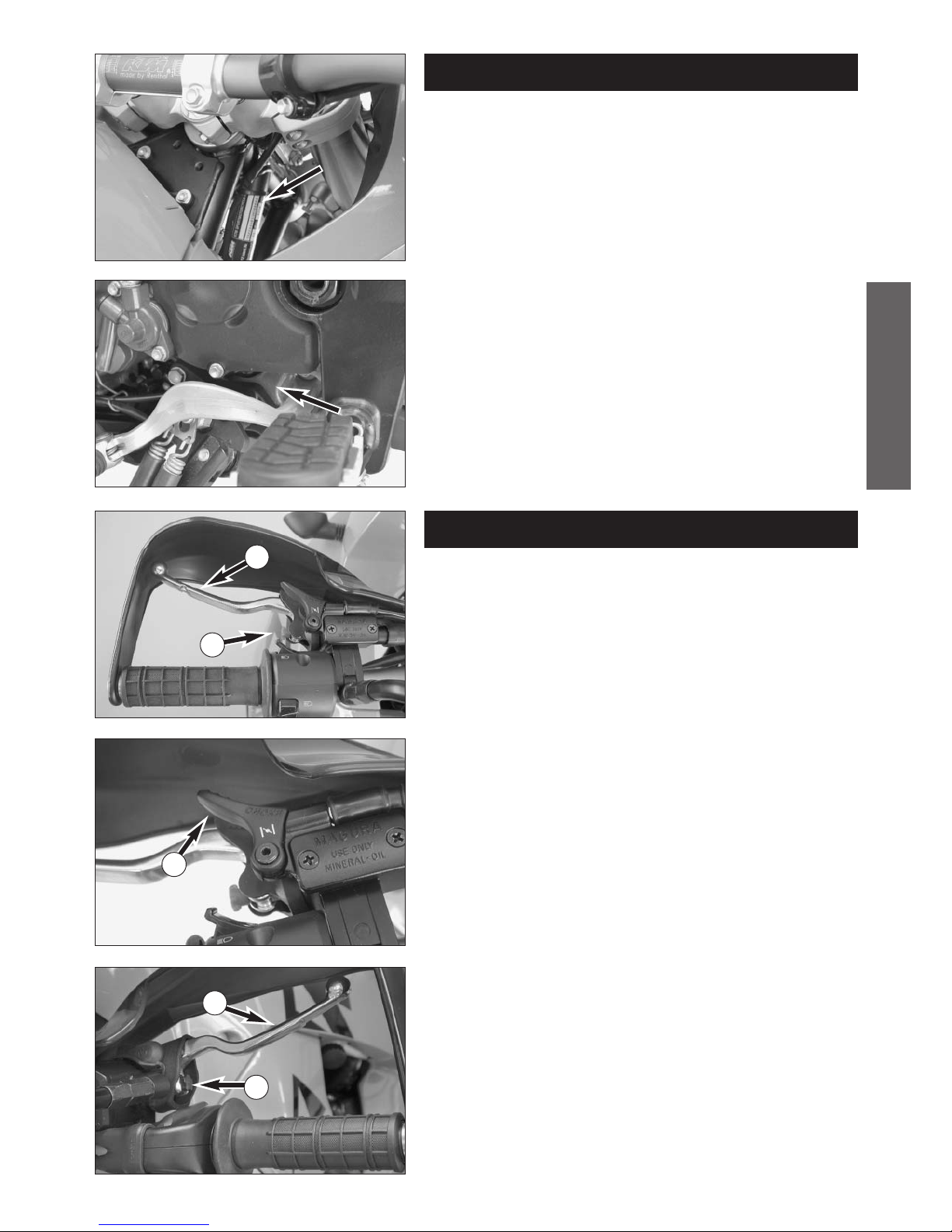
Clutch lever . . . . . . . . . . . . . . . . . . . . . . . . . . . . . . . . . . .5
Choke lever . . . . . . . . . . . . . . . . . . . . . . . . . . . . . . . . . . .5
Hand brake lever . . . . . . . . . . . . . . . . . . . . . . . . . . . . . .5
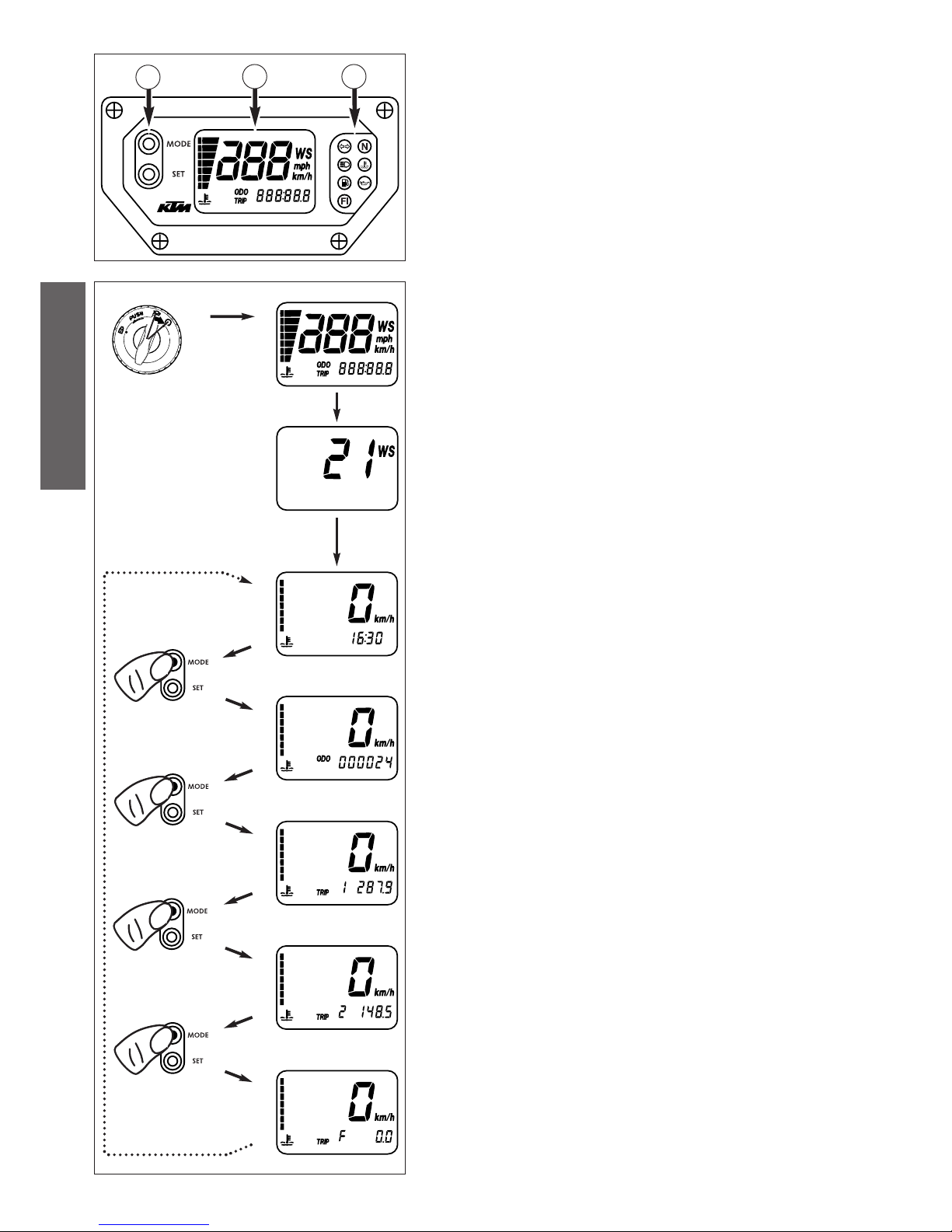
Multi-functional digital speedometer . . . . . . . . . . . . . . . .6
Display . . . . . . . . . . . . . . . . . . . . . . . . . . . . . . . . . . . . . .6
Setting options in the display . . . . . . . . . . . . . . . . . . . . . .7
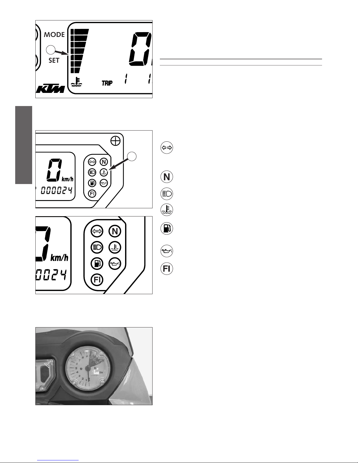
Cooling liquid temperature display . . . . . . . . . . . . . . . . .8
Indicator lamps . . . . . . . . . . . . . . . . . . . . . . . . . . . . . . . .8
Tachometer . . . . . . . . . . . . . . . . . . . . . . . . . . . . . . . . . .8
Ignition lock . . . . . . . . . . . . . . . . . . . . . . . . . . . . . . . . . .9
Combination switch . . . . . . . . . . . . . . . . . . . . . . . . . . . .9
Emergency OFF tip switch, light switch, starter tip switch . . .9
Storage compartment . . . . . . . . . . . . . . . . . . . . . . . . . .10
Filler caps . . . . . . . . . . . . . . . . . . . . . . . . . . . . . . . . . . .10
Seat lock . . . . . . . . . . . . . . . . . . . . . . . . . . . . . . . . . . . .10
Fuel taps . . . . . . . . . . . . . . . . . . . . . . . . . . . . . . . . . . . .10
Shift lever . . . . . . . . . . . . . . . . . . . . . . . . . . . . . . . . . . .11
Side stand . . . . . . . . . . . . . . . . . . . . . . . . . . . . . . . . . . .11
Foot brake pedal . . . . . . . . . . . . . . . . . . . . . . . . . . . . . .11
Compression damping of fork . . . . . . . . . . . . . . . . . . . .11
Rebound damping of fork . . . . . . . . . . . . . . . . . . . . . . .11
Spring preload of the fork . . . . . . . . . . . . . . . . . . . . . . .12
Damping action during compression of shock absorber . . .12
Rebound damping of shock absorber . . . . . . . . . . . . . .12
Shock absorber's preload adjuster . . . . . . . . . . . . . . . . .12
Baggage carrier plate . . . . . . . . . . . . . . . . . . . . . . . . . . .13
Grips . . . . . . . . . . . . . . . . . . . . . . . . . . . . . . . . . . . . . . .13
Footrests . . . . . . . . . . . . . . . . . . . . . . . . . . . . . . . . . . . .13
GENERAL TIPS AND WARNINGS FOR STARTING THE
MOTORCYCLE . . . . . . . . . . . . . . . . . . . . . . . . . . . . . . . . .14
Instructions for initial operation . . . . . . . . . . . . . . . . . .14
Running in the LC8 engine . . . . . . . . . . . . . . . . . . . . . .14
Accessories and payload . . . . . . . . . . . . . . . . . . . . . . . .14
DRIVING INSTRUCTIONS . . . . . . . . . . . . . . . . . . . . . . . . .15
Check the following before each start . . . . . . . . . . . . .15
Starting when the engine is cold . . . . . . . . . . . . . . . . . .16
Starting when the engine is warm or hot . . . . . . . . . . .16
Braking . . . . . . . . . . . . . . . . . . . . . . . . . . . . . . . . . . . . .17
Stopping and parking . . . . . . . . . . . . . . . . . . . . . . . . . .17
Starting off . . . . . . . . . . . . . . . . . . . . . . . . . . . . . . . . . .17
Shifting/Riding . . . . . . . . . . . . . . . . . . . . . . . . . . . . . . .17
Fuel . . . . . . . . . . . . . . . . . . . . . . . . . . . . . . . . . . . . . . . .18
PERIODIC MAINTENANCE SCHEDULE . . . . . . . . . . . . . . .20
MAINTENANCE WORK ON CHASSIS AND ENGINE . . . . .22
Removing and remounting the seat . . . . . . . . . . . . . . .22
Tool set . . . . . . . . . . . . . . . . . . . . . . . . . . . . . . . . . . . .22
Adjusting the fork and shock absorber . . . . . . . . . . . .23
Adjusting compression damping of fork . . . . . . . . . . . .23
Adjusting rebound damping of fork . . . . . . . . . . . . . . .23
Adjusting the spring preload on the fork . . . . . . . . . . .23
Compression damping of shock absorber . . . . . . . . . . .24
Rebound damping of shock absorber . . . . . . . . . . . . . .24
Adjusting the preload of the shock absorber . . . . . . . . .25
Breathing the fork legs . . . . . . . . . . . . . . . . . . . . . . . .25
Cleaning the dust sleeves of the telescopic fork . . . . . .25
Checking the chain tension . . . . . . . . . . . . . . . . . . . . .25
Correct chain tension . . . . . . . . . . . . . . . . . . . . . . . . . .26
Chain maintenance . . . . . . . . . . . . . . . . . . . . . . . . . . .26
Checking the chain for wear . . . . . . . . . . . . . . . . . . . . .26
General informations about KTM disc brakes . . . . . . . .27
Adjusting of free travel at the hand brake lever . . . . . .28
Checking of brake fluid level - front brake . . . . . . . . . .28
Refilling the front brake fluid reservoir . . . . . . . . . . . . .28
Checking the front brake pads . . . . . . . . . . . . . . . . . . .28
Changing the basic position of the foot brake lever . . . .29
Checking rear brake fluid level . . . . . . . . . . . . . . . . . . .29
Refilling the rear brake fluid reservoir . . . . . . . . . . . . . .29
Checking the rear brake pads . . . . . . . . . . . . . . . . . . . .29
Dismounting and mounting the front wheel . . . . . . . . .30
Dismounting and mounting the rear wheel . . . . . . . . . .31
Checking the shock absorption rubbers in the rear hub . . . . . .31
Tires, air pressure . . . . . . . . . . . . . . . . . . . . . . . . . . . . .32
Checking spoke tension . . . . . . . . . . . . . . . . . . . . . . . . .32
Battery . . . . . . . . . . . . . . . . . . . . . . . . . . . . . . . . . . . . .32
Demounting and mounting the battery . . . . . . . . . . . . .33
Charging the battery . . . . . . . . . . . . . . . . . . . . . . . . . .33
Connecting the battery jumper cable . . . . . . . . . . . . . .33
Main fuse . . . . . . . . . . . . . . . . . . . . . . . . . . . . . . . . . .34
Fuses for individual current consumers . . . . . . . . . . . . .34
Replacing the headlight lamps . . . . . . . . . . . . . . . . . . . .35
Adjusting the headlight range . . . . . . . . . . . . . . . . . . . .36
Replacing the brake and tail light bulbs . . . . . . . . . . . .36
Replacing the flasher bulbs . . . . . . . . . . . . . . . . . . . . . .36
Cooling system . . . . . . . . . . . . . . . . . . . . . . . . . . . . . . .37
Checking the cooling liquid level in the compensating tank . . .37
Checking the cooling liquid level in the radiator . . . . . .38
Changing the original position of the clutch lever . . . . .38
Checking the oil level of the hydraulic clutch . . . . . . . . .38
Checking and adjusting the throttle cable play . . . . . . .38
Checking and adjusting the choke cable play . . . . . . . .39
Adjusting the engine idle speed . . . . . . . . . . . . . . . . . . .39
Engine oil . . . . . . . . . . . . . . . . . . . . . . . . . . . . . . . . . . .39
Checking the engine oil level . . . . . . . . . . . . . . . . . . . .39
Changing the engine oil and the oil filter, cleaning
the oil screen . . . . . . . . . . . . . . . . . . . . . . . . . . . . . . . .40
Activating the ignition curve for low-octane fuel . . . . .43
TROUBLE SHOOTING . . . . . . . . . . . . . . . . . . . . . . . . . . . .44
CLEANING . . . . . . . . . . . . . . . . . . . . . . . . . . . . . . . . . . . . .46
CONSERVATION FOR WINTER OPERATION . . . . . . . . . .46
STORAGE . . . . . . . . . . . . . . . . . . . . . . . . . . . . . . . . . . . . .46
RE-INITIATION AFTER TIME OF STORAGE . . . . . . . . .46
TECHNICAL SPECIFICATIONS - CHASSIS . . . . . . . . . . . . .47
TECHNICAL SPECIFICATIONS - ENGINE . . . . . . . . . . . . . .49
HEAD WORD INDEX . . . . . . . . . . . . . . . . . . . . . . . . . . . . .51
WIRING DIAGRAM . . . . . . . . . . . . . . . . . . . . . . . .APPENDIX
INDEX
Page Page

ENGLISH
5
Chassis number
The chassis number is located on the right side of the steering head tube
and on the type label. Write this number into the relevant area on page 1.
Engine number, engine type
The engine number and engine type are embossed in the engine case near
the shift lever. Write this number into the relevant area on page 1.
Clutch lever
The clutch lever 1is located on the left side of the handlebar. The adjusting
screw Ais used to change the original position of the clutch lever (see
maintenance work on chassis and engine).
The clutch is hydraulically actuated and adjusts itself automatically.
Choke lever
If the choke lever 2is pulled backwards, a bore in the carburetors will be
opened in the carburetor through which the engine may draw in additional
fuel. This produces a „rich“ fuel/air mixture necessary for cold start. The
fuel quantity and thus the engine speed are determined by the choke lever
position.
At temperatures over 5°C (41°F) it will suffice to pull the choke lever half
way out. At temperatures below 5°C (41°F) the choke lever should be pul-
led all the way out. The hole is closed again by pushing the choke lever all
the way back in.
Hand brake lever
The hand brake lever 3is mounted on the handlebars on the right and
actuates the front wheel brake. The adjusting screw Bcan be used to
change the basic position of the hand brake lever (see "Maintenance").
SERIAL NUMBER LOCATIONS
OPERATION INSTRUMENTS
A
2
1
3
B

ENGLISH
6
Multi-functional digital speedometer
The universal instrument is divided into 3 parts.
Use the MODE and SET 1button to change the display and the basic set-
tings in the display.
Display 2shows all of the information that may be of interest to you.
5 display modes can be selected with the MODE button.
The indicator lamps 3provide additional information on the motorcycle's
running condition.
Display
TEST
When you switch on the ignition, all of the display elements will light up for
1 second for the function test.
WS (wheel size)
The display will change and show the diameter of the front wheel in inches
for 1 second (WS = wheel size).
Then the CLOCK mode will be displayed, or the mode that was active
when the ignition was switched off.
CLOCK
You will recognize the CLOCK display by the blinking dots between the
hours and minutes. It displays the speed, temperature of the cooling liquid
and the clock.
To switch to the next display mode, press the MODE button.
ODO
The speed, temperature of the cooling liquid and the total kilometers or
miles traveled are shown in the ODO mode.
To switch to the next display mode, press the MODE button.
TRIP 1
The TRIP 1 mode shows the speed, the temperature of the cooling liquid
and the trip odometer 1.
To switch to the next display mode, press the MODE button.
TRIP 2
The TRIP 2 mode shows the speed, the temperature of the cooling liquid
and the trip odometer 2.
To switch to the next display mode, press the MODE button.
TRIP F
The TRIP F (fuel) mode shows the speed, the temperature of the cooling
liquid and the distance traveled since reaching the low-fuel mark (the low-
fuel indicator lamp will blink).
To return to the UHR mode, press the MODE button.
123
TEST
WS
ODO
CLOCK
TRIP 1
TRIP 2
TRIP F

ENGLISH
7
Setting options in the display
KILOMETERS OR MILES.
You can have the speed and distance shown in kilometers or miles in the
display. The display can be adapted to the respective country on long-
distance trips.
To switch from kilometers to miles, switch on the ignition and press the
MODE 1button for approx. 10 seconds. The km/h display will switch to
mph. The speed and the stored distances will be converted and displayed in
miles.
To return to kilometers, proceed as described above.
CLOCK
Switch on the ignition and change to the CLOCK mode.
Simultaneously press MODE 1and SET 2. The numbers on the clock will
start to blink. Use the MODE button to set the hours and the SET button to
set the minutes.
The press the MODE and SET buttons simultaneously.
NOTE:
0:00 will be displayed if the clock is not supplied with electricity. This can be
caused by a defective fuse or a fault in the board electric system (see
Troubleshooting).
TRIP 1
The trip meter 1 runs continuously and counts up to 999.9. It can be used
to measure the length of a certain route on a trip or the distance between
two refueling stops.
To return the trip meter 1 to zero, switch on the ignition, change to the
TRIP 1 mode and press the SET button.
RESETTING TRIP 2
The trip meter 2 runs continuously and counts up to 999.9. It can be used
similarly to TRIP 1 or together with a switch available as an accessory (see
below) for trips according to a roadbook.
To return the trip meter 2 to zero, switch on the ignition, change to the
TRIP 2 mode and press the SET button.
NOTE
A Tripmaster switch (Part no. 582.14.069.044) is available as an accessory
and enhances the trip meter 2 functions. You can correct the displayed
route by increasing or decreasing in increments of 0.1. For example, if you
have taken the wrong road when driving according to a roadbook, you can
easily correct the display to correspond to the roadbook again. It can also
be used to change the display modes. The switch is mounted on the hand-
lebars so that you can keep your hands on the handlebars.
TRIP F
When the fuel level reaches the reserve mark, the display will automatically
switch to TRIP F and begin to count (no matter which display mode was
active before). At the same time, the fuel warning lamp will start to blink.
You will still have enough reserve fuel for aprox 50 kilometers (30 miles).
After refueling, it will take approx. 3 minutes for TRIP F to automatically
reset to 0 and return to the previous display mode.
10 sec
1
1
2
2
2

ENGLISH
8
Cooling liquid temperature display
The temperature display 1is shown in 7 bars. The more bars that light up,
the hotter the cooling liquid. When the lowest bar lights up, the cooling
liquid has reached a temperature of approx. 40°C (104°F). When the upper
bar lights up 120°C (248°F), all of the bars will start to blink and the red
warning lamp 2will light up.
WARNING
POSSIBLE CAUSES FOR AN INCREASE IN TEMPERATURE, CAUSING THE RED WARNING LIGHT
FOR THE COOLING LIQUID TEMPERATURE TO LIGHT UP:
– DRIVING TOO SLOWLY AND DRIVING WITH A HEAVY LOAD AT HIGH AIR TEMPERATURES
– NOT ENOUGH COOLING LIQUID IN THE SYSTEM
– THE VENTILATOR ON THE RADIATOR IS NOT RUNNING
– IMPROPER USE OF THE CLUTCH WHEN DRIVING SLOWLY
Indicator lamps
The green indicator lamp will blink in the blinker rhythm when the
blinker is switched on.
NOTE:
The indicator lamp will blink slower when a blinker is broken.
The green indicator lamp will light up when the gearbox is in an
idling position.
The blue indicator lamp will light up when the high beams are
switched on.
The red warning light will light up when the cooling liquid has
reached a temperature of approx. 120°C (248°F).
The orange warning light will start to blink when the fuel level has
reached the reserve mark. At the same time the display will auto-
matically change to TRIP F (see TRIP F).
The red warning lamp lights up when the ignition is switched on
but the engine is not running. When the engine is started, the war-
ning lamp will go out as soon as the oil pressure is high enough.
This indicator lamp has no function.
Tachometer
The tachometer shows the engine speed in revolutions per minute. Do not
run the engine beyond the black mark at 9500 rpm.
The speed limiter will set in at 9600 rpm, drastically reducing the engine
power above this rotational speed.
120°C (248°F)
110°C (230°F)
100°C (212°F)
70°C (158°F)
60°C (140°F)
50°C (122°F)
40°C (104°F)
1
2

ENGLISH
9
Ignition lock
The ignition lock 1has 3 switching positions.
Ignition off, (engine can't be started)
Ignition on, (engine can be started)
Ignition off, handlebar blocked
To switch the ignition to position turn the ignition key to position
and firmly press it into the
lock. Turn the handlebar all the way to the left, then turn the ignition
key to the left.
The ignition key can be withdrawn in position and .
Combination switch
The rocker switch LIGHTS 2actuates the high beam or low beam.
= High-beam light
= Low-beam light
The light signal (high beam) is actuated with button 3.
The indicator switch 4returns to central position after actuation.
Press flasher switch towards switch housing to switch off the flasher.
The horn is sounded with button 5.
Emergency OFF tip switch, light switch, starter tip switch
The emergency off switch 6is provided for emergency situations and
should not be used to switch off the engine.
The engine is ready for operation in position (ignition circuit and starter
circuit are switched on).
The engine cannot be started in position (ignition circuit and starter
circuit are interrupted).
The light switch 7has 3 positions:
= Light off
= Parking light on
= Headlight on
Use the starter tip switch 8to operate the electric starter.
7
8
6
1
2
3
4
2
5

ENGLISH
10
Storage compartment
A storage compartment is located under the seat to hold small, frequently
used items.
To open, turn the quick release 1approx. 180° in a counterclockwise
direction and lift the cover. To lock, close the cover, insert the quick release
in the dolly and turn 180° in a clockwise direction.
Filler caps
The 950 Adventure has 2 separate fuel tanks.
Both filler caps 2can be locked and are equipped with a tank vent system.
To open, insert the ignition key, turn 45° in a clockwise direction and fold
up the filler cap.
The ignition key can be pulled out to open the other filler cap. Simply press
on the filler cap to close.
Seat lock
The seat is unlocked by inserting the ignition key in the lock 3on the side
and turning the key in a counterclockwise direction. See "Maintenance
Work" to remove and remount the seat.
Fuel taps
The 950 Adventure is equipped with 3 fuel taps which only need to be clo-
sed to remove the fuel tank.
Fuel cannot flow to the carburetors if the fuel pump is not running, so the
fuel tap 4does not need to be closed when the motorcycle is switched
off.
Both fuel taps 5must be open when the motorcycle is running. The level
in the fuel tanks is equalized by means of a connecting hose.
1
2
3
4
5
5

ENGLISH
11
Shift lever
The shift lever is mounted on the left side of the engine. The position of
the gears is shown in the illustration. Neutral, or the idle speed, is located
between first and second gear.
Side stand
The side stand 1is coupled with a safety starter system. Pay attention to
Driving Instructions.
NOTE:
A center stand is available as an accessory from your authorized KTM
workshop. The side stand does not need to be removed.
Foot brake pedal
The foot brake pedal 2is located in front of the right footrest. Its basic
position can be adjusted to your seat position (see maintenance work).
Compression damping of fork
The fork's damping action during compression travel (compression dam-
ping) can be adjusted. This allows you adjust the damping behavior to
match your driving style and the payload.
The adjusting screws 4are located under the cap 3on the lower end of
the fork legs.
More information is provided in the chapter "Adjusting the fork and shock
absorber.“
Rebound damping of fork
The fork's damping action during rebound travel (rebound damping) can
also be adjusted. This allows you adjust the damping behavior to match
your driving style and the payload.
The adjusting screws 5are located on the upper end of the fork legs.
More information is provided in the chapter "Adjusting the fork and shock
absorber.“
2,3,4,5,6
N
1
1
2
34
5
5

ENGLISH
12
Spring preload of the fork
The fork's preload can be adjusted by means of the adjusting screws 1.
More information is provided in the chapter "Adjusting the fork and shock
absorber.“
Damping action during compression of shock absorber
The shock absorber's damping action during compression travel (compres-
sion damping) can be adjusted. This allows you adjust the shock absorber's
damping behavior to match your driving style and the payload.
The damping rate can be adjusted in the low and high-speed range (Dual
Compression Control). The designation low and high-speed refers to the
movement of the shock absorber and not to the motorcycle's driving speed.
The adjusting screw 2for the low-speed range can be adjusted with a
screwdriver.
The adjusting screw 3for the high-speed range can be adjusted with a
17 mm socket wrench.
More information is provided in the chapter "Adjusting the fork and shock
absorber.“
Rebound damping of shock absorber
The shock absorber's damping action during rebound travel (rebound dam-
ping) can also be adjusted. This allows you adjust the damping behavior to
match your driving style and the payload.
The adjusting screw 4is located on the bottom of the shock absorber.
More information is provided in the chapter "Adjusting the fork and shock
absorber.“
Shock absorber's preload adjuster
The shock absorber's preload adjuster is infinitely variable by means of the
hand wheel 5. This allows the shock absorber to be adapted to match your
body weight and the payload.
The hand wheel can be swung out to make adjustments.
2
3
4
5
1

ENGLISH
13
Baggage carrier plate
The base plate for your choice of case system can be attached to the bag-
gage carrier plate 1.
WARNING
–D
ONOT LOAD MORE THAN 8 KG ON THE TRUNK CARRIER RACK.
–OBSERVE THE BAGGAGE MANUFACTURER'SINSTRUCTIONS.
Grips
The passenger can hold on to both grab handles 2.
Footrests
The passenger footrests 3fold up.
1
2
2
3

ENGLISH
14
GENERAL TIPS AND WARNINGS FOR STARTING THE MOTORCYCLE
Instructions for initial operation
–Verify that your KTM dealer performed the PREPARATION
OF VEHICLE jobs (see Customer Service Manual).
–Read these operating instructions carefully before your first
ride.
–Enter the chassis, engine and key numbers on page 1.
–Familiarize yourself with the operating elements.
–Adjust the hand brake lever and foot brake lever to your
most comfortable position.
–This motorcycle is equipped with 2 catalytic converters.
Leaded fuel will destroy the catalytic converters. Please use
unleaded fuel only.
–Get used to handling the motorcycle on an empty parking
lot, before starting on a longer drive. Also try to drive as slo-
wly as possible and in standing position, to improve your
feeling for the vehicle.
–Do not drive along off-road tracks which go beyond your
abitily and experience.
–Hold the handlebars with both hands and leave your feet on
the foot rests while driving.
–Remove your foot from the foot brake lever when you are
not braking. If the foot brake lever is not released the brake
pads rub continuously and the braking system is
overheated.
–Do not make any alterations to the motorcycle and always
use ORIGINAL KTM SPARE PARTS. Spare parts from other
manufacturers can impair the safety of the motorcycle.
–Motorcycles are sensitive to changes in the weight
distribution. Read the section on "Accessories and payload“
when carrying luggage.
–Pay attention to running-in procedure.
Running in the LC8 engine
Even finely machined surfaces of engine parts have rougher
surfaces than parts that slide on each other for a long time.
Therefore, every engine must be run in. For this reason, do not
demand maximum performance from the engine for the first
1000 kilometers (620 miles). The vehicle must be run in at low,
changing performance level for the first 1000 KM (620 miles).
The maximum number of revolutions per minute must not go
exceed 6500 rpm. Once you have run your engine in for
1000 km, you may push it to its 9500 rpm limit , i.e. up to the
red zone indicated in the tachometer. Exceeding the above
listed rotations as well as pushing high rpm when the engine is
cold will have an adverse effect on the life of your engine.
WARNING
–W
EAR SUITABLE CLOTHING WHEN DRIVING A MOTORCYCLE. CLEVER
KTM DRIVERS ALWAYS WEAR A HELMET, BOOTS, GLOVES AND A
JACKET, REGARDLESS OF WHETHER DRIVING ALL DAY OR JUST FOR A
SHORT TRIP. THE PROTECTIVE CLOTHING SHOULD BE BRIGHTLY COLO-
RED SO THAT OTHER VEHICLE CAN SEE YOU AS EARLY AS POSSIBLE.
YOUR PASSENGER WILL ALSO NEED SUITABLE PROTECTIVE CLOTHING.
–DO NOT DRIVE AFTER HAVING CONSUMED ALCOHOL.
–A
LWAYS TURN ON THE LIGHT TO MAKE SURE THAT OTHER DRIVERS
BECOME AWARE OF YOU AS EARLY AS POSSIBLE.
–DRIVE AT A MODERATE SPEED FOR THE FIRST FEW KILOMETERS OF
EACH TRIP TO ALLOW THE TIRES TO REACH THE NECESSARY OPERATING
TEMPERATURE. MAXIMUM ROAD GRIP IS ASSURED WHEN THE TIRES
ARE WARM.
–T
HE FRONT AND REAR WHEEL ARE ALLOWED TO BE FITTED ONLY WITH
TIRES THAT HAVE THE SAME PROFILE TYPE.
–THE TIRES MUST BE DESIGNED FOR A MAXIMUM SPEED OF 240 KPH
(SPEED SYMBOL V) AND MUST BE AUTHORIZED BY KTM.
–D
ONOT EXCEED THE RESPECTIVE MAXIMUM SPEED FOR TIRES
DESIGNED WITH A SPEED INDEX OF LESS THAN "V“ (240 KPH).
A STICKER SHOWING THE MAXIMUM SPEED MUST BE AFFIXED TO THE
MOTORCYCLE WITHIN THE DRIVER'S FIELD OF VISION.
WARNING
–NEW WHEELS HAVE A SMOOTH SURFACE, WHICH MEANS
THAT THEY MUST BE RUN IN TO ACHIEVE FULL GRIP. FOR THIS PURPOSE,
RIDE THE MOTORCYCLE CAREFULLY AT MODERATE SPEED DURING THE
FIRST 200 KILOMETERS WITH NEW TIRES, TILTING THE VEHICLE AT DIFFE-
RENT ANGLES SO THAT ALL SECTIONS ARE PROPERLY ROUGHENED. TIRES
WILL NOT DISPLAY THEIR FULL GRIP CHARACTERISTICS UNTIL THEY ARE
PROPERLY RUN IN.
–WHEELS WITH A DIFFERENT RIM DIAMETER OR OTHER RIM WIDTH
MAY NOT BE MOUNTED OTHERWISE THE VEHICLE HANDLING WILL NO
LONGER BE SAFE.
–O
BSERVE THE TRAFFIC REGULATIONS, DRIVE DEFENSIVELY AND TRYING
TO LOOK AHEAD AS FAR AS POSSIBLE SO THAT ANY HAZARDS CAN BE
RECOGNIZED AS EARLY AS POSSIBLE.
–C
HOOSE YOUR DRIVING SPEED ACCORDING TO THE CONDITIONS AND
YOUR DRIVING SKILLS.
–D
RIVE CAREFULLY ON UNKNOWN ROADS OR ON UNFAMILIAR TRIALS.
–RENEW THE VIZOR ON YOUR HELMET OR THE GLASS OF YOUR
GOGGLES ON TIME SO AS TO ENSURE OPTIMUM VISION IN ANY
SITUATION. WHEN LIGHT SHINES DIRECTLY ON SCRATCHED VISOR OR
GOGGLES, THE OPERATOR WILL BE BLINDED.
–N
EVER LEAVE YOUR MOTORCYCLE WITHOUT SUPERVISION IF THE
ENGINE IS RUNNING.
Accessories and payload
Accessory parts and baggage can significantly decrease a
motorcycle's driving stability. Please observe the following
warnings.
WARNING
–NEVER DRIVE FASTER THAN 130 KPH (80 MPH) IF YOU HAVE MOUN-
TED ACCESSORY PARTS ON YOUR MOTORCYCLE. ACCESSORY PARTS
CAN SIGNIFICANTLY IMPAIR THE MOTORCYCLE'SHANDLING, ESPECI-
ALLY IN THE MAXIMUM SPEED RANGE.
– NEVER DRIVE FASTER THAN 130 KPH (80 MPH) IF YOUR MOTORCY-
CLE IS LOADED WITH CASES OR OTHER BAGGAGE. THEY WILL IMPAIR
THE MOTORCYCLE'SHANDLING AT HIGHER SPEEDS AND CAN EASILY
CAUSE IT TO GO OUT OF CONTROL
–IF YOU HAVE CASES MOUNTED, DO NOT EXCEED THE MANUFACTU-
RER'SRECOMMENDED MAXIMUM PAYLOAD.
–F
ASTEN THE BAGGAGE CLOSE TO THE CENTER OF THE MOTORCYCLE
AND DISTRIBUTE THE WEIGHT EVENLY ON THE FRONT AND REAR
WHEELS AND ON THE LEFT AND RIGHT.
–B
AGGAGE MUST BE SECURELY AND ADEQUATELY FASTENEND; LOOSE
BAGGAGE WILL SIGNIFICANTLY IMPAIR DRIVING SAFETY.
–A
HIGH PAYLOAD WILL CHANGE THE MOTORCYCLE'SHANDLING AND
CONSIDERABLY INCREASE THE BRAKING DISTANCE; ADAPT YOUR
DRIVING SPEED ACCORDINGLY.
This manual suits for next models
1
Table of contents
Other KTM Motorcycle manuals

KTM
KTM Freeride 250 R EU User manual

KTM
KTM 400 EXC EU 2010 User manual

KTM
KTM 250 EXC-F EU 2010 User manual

KTM
KTM 125 DUKE 2022 Manual

KTM
KTM 450 SX-F Manual

KTM
KTM Freeride 250 R EU 2014 Manual

KTM
KTM 350 SX-F EU 2014 Manual

KTM
KTM 85 SX 2019 User manual

KTM
KTM 1190 RC8 R USA User manual

KTM
KTM 890 ADVENTURE 2022 User manual

KTM
KTM 950 SUPERMOTO R User manual

KTM
KTM 790 DUKE 2021 User manual

KTM
KTM 250 SX Series Manual

KTM
KTM 1290 Super Adventure User manual

KTM
KTM 350 SX-F Cairoli replica User manual

KTM
KTM 450 SX-F EU 2009 Manual

KTM
KTM 250 SX-F EU 2014 Manual

KTM
KTM 250 SX-F 2019 Manual

KTM
KTM 690 DUKE R EU User manual

KTM
KTM 500 EXC AUS User manual