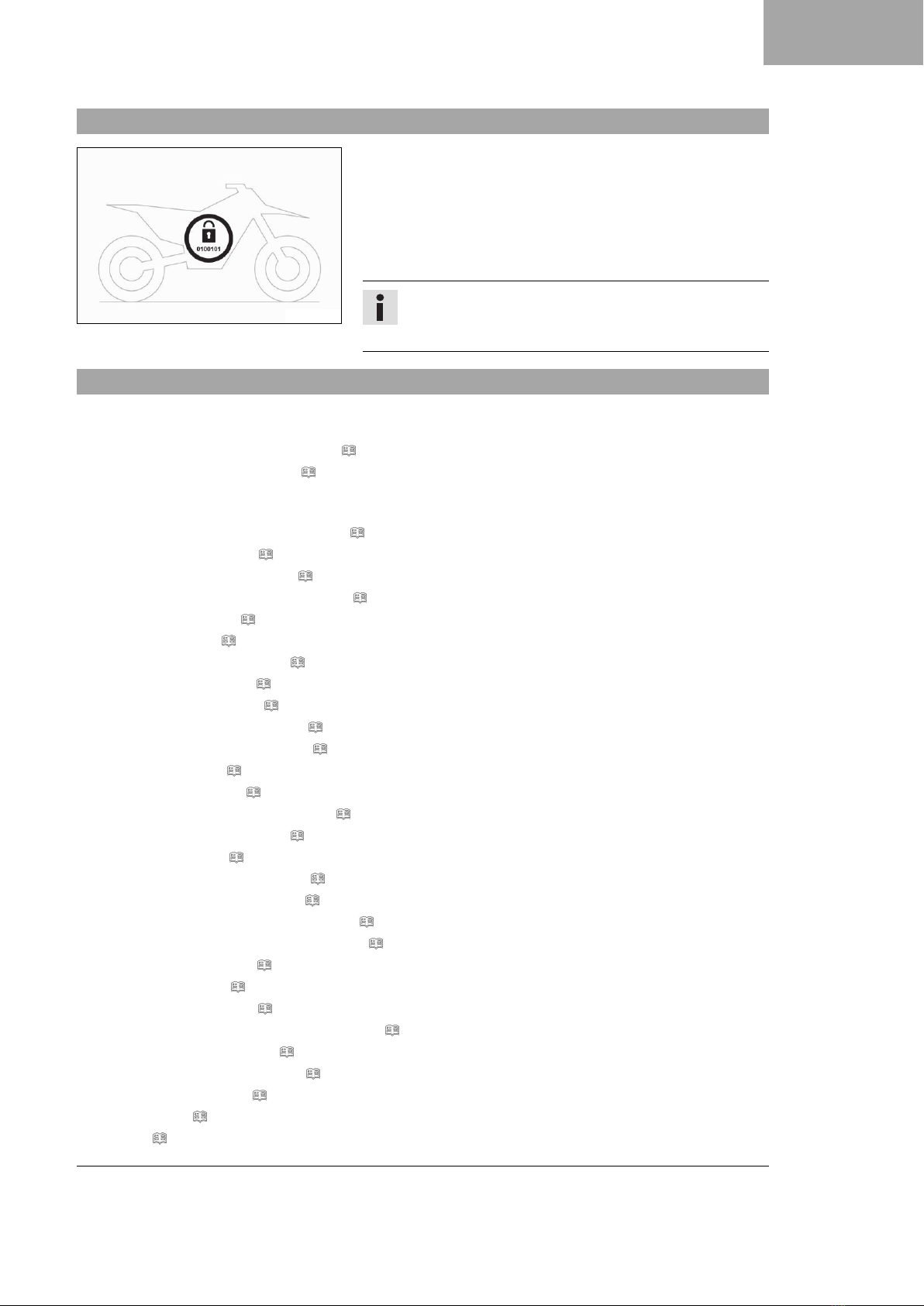
KTM Freeride 250 F 2019 Manual

SETUP INSTRUCTIONS 2019
Freeride 250 F
Art. no. 3213879en


INTRODUCTION
*3213879en*
3213879en
07/2018
INTRODUCTION
Perform the work described in these setup instructions before the vehicle is delivered to the customer.
Read the setup instructions in their entirety before beginning work.
These setup instructions were written to correspond to the latest state of this series. We reserve the right to make
changes in the interest of technical advancement without at the same time updating this manual.
We shall not provide a description of general workshop methods. Likewise, safety rules that apply in a workshop
are not specified here. It is assumed that the work will be performed by a fully trained mechanic.
All specifications are non-binding. KTM Sportmotorcycle GmbH specifically reserves the right to modify or delete
technical specifications, prices, colors, forms, materials, services, designs, equipment, etc., without prior notice
and without specifying reasons, to adapt these to local conditions, as well as to stop production of a particular
model without prior notice. KTM accepts no liability for delivery options, deviations from figures and descriptions,
misprints, and other errors. The models portrayed partly contain special equipment that does not belong to the
regular scope of supply.
© 2018 KTM Sportmotorcycle GmbH, Mattighofen Austria
All rights reserved
Reproduction, even in part, as well as copying of all kinds, is permitted only with the express written permission
of the copyright owner.
ISO 9001(12 100 6061)
KTM applies quality assurance processes that lead to the highest possible product quality as
defined in the ISO 9001 international quality management standard.
Issued by: TÜV Management Service
KTM Sportmotorcycle GmbH
Stallhofnerstraße 3
5230 Mattighofen, Austria
This document is valid for the following models:
Freeride 250 F EU (F8103S4)

1 MEANS OF REPRESENTATION
2
1.1 Symbols used
The meaning of specific symbols is described below.
Indicates an expected reaction (e.g. of a work step or a function).
Indicates an unexpected reaction (e.g. of a work step or a function).
Indicates a page reference (more information is provided on the specified page).
Indicates information with more details or tips.
Indicates the result of a testing step.
Indicates a voltage measurement.
Indicates a current measurement.
Indicates a resistance measurement.
Indicates the end of an activity including potential rework.
1.2 Formats used
The typographical formats used in this document are explained below.
Proprietary name Indicates a proprietary name.
Name®Indicates a protected name.
Brand™ Indicates a brand available on the open market.
Underlined terms Refer to technical details of the vehicle or indicate technical terms, which
are explained in the glossary.

SETUP 2
3
2.1 Transport mode
H02712-01
This vehicle was blocked for transport in the software.
To operate the vehicle, the vehicle electronics must be enabled.
This process is conducted during initial setup in KTM Dealer.net.
Enabling ensures that the initial setup in KTM Dealer.net is docu-
mented.
Enabling can be performed either temporarily, e.g. for a test ride,
or permanently for vehicle handover.
Info
Make sure that the vehicle is permanently enabled before
handing it over to the customer.
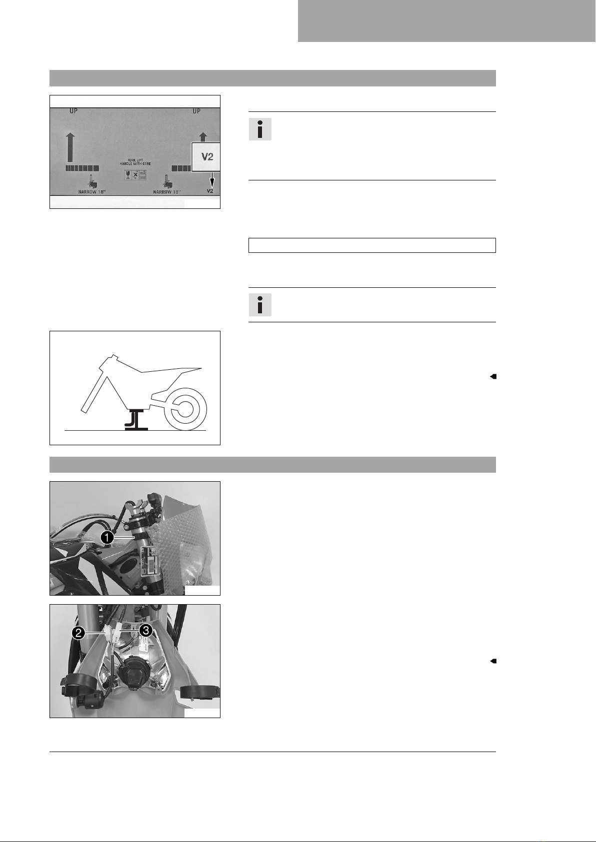
2.2 Unpacking and setting up the vehicle
Condition
Packaging V2
–Unpack and set up the V2 vehicle. ( p. 5)
–Remove V2 headlight mask. ( p. 5)
Condition
Packaging V12
–Unpack and set up the V12 vehicle. ( p. 6)
–Install V12 fork legs. ( p. 6)
–Install V12 shock absorber. ( p. 7)
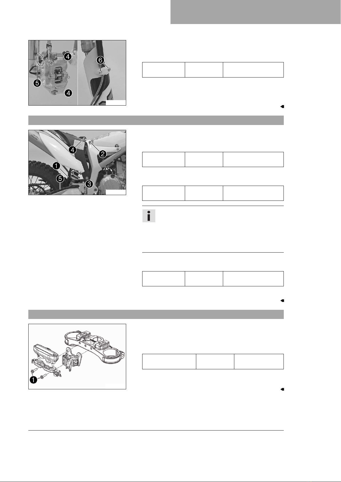
–Install C12 combination instrument. ( p. 7)
–Stick on the reflector. ( p. 8)
–Install handlebars. ( p. 8)
–Install the handlebar cushion. ( p. 9)
–Install left side controls. ( p. 9)
–Install right side controls. ( p. 11)
–Install left and right rear mirrors. ( p. 12)
–Install left and right hand guards. ( p. 12)
–Install front fender. ( p. 13)
–Install the front wheel. ( p. 13)
–Install the front and rear turn signals. ( p. 14)
–Install the license plate lamp. ( p. 15)
–Install the reflector. ( p. 15)
–Route the front turn signal cable. ( p. 15)
–Route the rear turn signal cable. ( p. 16)
–Install the license plate holder extension. ( p. 19)
–Remove the motorcycle from the lift stand. ( p. 20)
–Install the engine guard. ( p. 20)
–Install the footrests. ( p. 20)
–Charge the 12 V battery. ( p. 22)
–Install the headlight mask with the headlight. ( p. 24)
–Check the headlight setting. ( p. 24)
–Set the combination instrument. ( p. 25)
–Set kilometers or miles. ( p. 26)
–Set the clock. ( p. 26)
–Refuel. ( p. 27)

2 SETUP
4
–Unpack and mount the KTM PowerParts included in the delivery (optional).
Info
Read the accompanying KTM PowerParts fitting instructions.
–Remove remaining protective film.
–Attach the stickers included in the scope of supply (optional).
–Prepare the vehicle according to the specifications in the KTM Dealer.net for handover to the customer.

SERVICE WORK ON THE CHASSIS 3
5
3.1 Unpacking and setting up the V2 vehicle
E00851-10
–Remove the box and the plastic packaging.
Info
An assistant prevents the motorcycle from falling over.
To avoid damaging the motorcycle during the setup,
leave the protective film on the vehicle until you have
finished.
–Remove and unpack the separate enclosure and components.
Check that the scope of supply is complete using the enclosed
packing list.
–Have a lift stand available.
Lift stand (78929955100)
–Carefully loosen and remove the tension belt of the footrest
mount.
Info
An assistant prevents the motorcycle from falling over.
402050-01
–Together with an assistant, take the vehicle off the pallet.
–Position the vehicle on a lift stand.
–Check the vehicle for transport damage.
3.2 Removing V2 headlight mask
F01233-10
–Remove the spare key and KEYCODECARD keep in a safe place
for the handover.
–Loosen rubber strap 1and tilt the headlight mask forwards.
E00971-10
–Disconnect the plug-in connector 2of the headlight and the
plug-in connector 3of the ignition lock.
–Lay down the headlight mask carefully to the side and protect
from damage.

3 SERVICE WORK ON THE CHASSIS
6
3.3 Unpacking and setting up the V12 vehicle
E00850-10
–Remove the box and the plastic packaging.
Info
An assistant prevents the motorcycle from falling over.
To avoid damaging the motorcycle during the setup,
leave the protective film on the vehicle until you have
finished.
–Remove and unpack the separate enclosure and components.
Check that the scope of supply is complete using the enclosed
packing list.
–Remove the spare key and KEYCODECARD keep in a safe place
for the handover.
–Have a lift stand available.
Lift stand (78929955100)
–Remove the two cable ties on the triple clamp.
402051-01
–Together with an assistant, take the vehicle off the pallet.
–Position the vehicle on a lift stand.
–Check the vehicle and components for transport damage.
3.4 Installing V12 fork legs
402556-10
–Position the fork legs.
Bleeder screws 1are positioned toward the front.
Info
Grooves are milled into the side of the upper end of the
fork legs. The second milled groove (from the top) must
be flush with the upper edge of the upper triple clamp.
E00974-10
–Tighten screws 2.
Guideline
Screw, top triple
clamp
M8 22 Nm (16.2 lbf ft)
–Tighten screws 3.
Guideline
Screw, bottom triple
clamp
M8 18 Nm (13.3 lbf ft)

SERVICE WORK ON THE CHASSIS 3
7
F01200-10
–Position the brake caliper. Mount and tighten screws 4with
the spacers.
Guideline
Screw, front
brake caliper
M8 25 Nm (18.4 lbf ft)
Loctite®243™
–Connect plug-in connector 5and mount the cable tie(s).
–Position the brake line, wiring harness, and clamp. Mount and
tighten screws 6.
3.5 Installing V12 shock absorber
F01209-11
–Push splash protector 1to the side and position the shock
absorber. Mount and tighten screw 2.
Guideline
Screw, top
shock absorber
M12 80 Nm (59 lbf ft)
Loctite®2701™
–Mount and tighten screw 3.
Guideline
Screw, bottom
shock absorber
M12 80 Nm (59 lbf ft)
Loctite®2701™
Info
The heim joint for the shock absorber on the link fork
is Teflon coated. It must not be lubricated with grease,
nor with any other lubricants. Lubricants dissolve the
Teflon coating, thereby drastically reducing the service
life.
–Mount and tighten screw 4.
Guideline
Screw, sub-
frame top
M10 45 Nm (33.2 lbf ft)
Loctite®243™
–Attach brake line 5.
3.6 Installing V12 combination instrument
H02569-10
–Position the connector board and combination instrument on
the upper triple clamp.
–Mount and tighten screws 1.
Guideline
Remaining screws,
chassis
M6 10 Nm (7.4 lbf ft)
–Route the clutch line with the clutch master cylinder toward
the front between the upper and lower triple clamps.

3 SERVICE WORK ON THE CHASSIS
8
3.7 Sticking on the reflector
F01234-01
–Make sure that the reflectors are glued on to the left and right
fork leg.
» If there are no reflectors stuck on:
–Stick on the reflector.
Info
The reflectors must not be covered by trim
parts.
3.8 Installing handlebars
F01235-10
–Remove screws 1. Take off the handlebar supports.
–Place the handlebar supports in the required position. Mount
and tighten screws 1.
Guideline
Screw, handle-
bar support
M10 40 Nm (29.5 lbf ft)
Loctite®243™
Info
Position the left and right handlebar supports evenly.
E00957-10
Warning
Danger of accidents A repaired handlebar poses a
safety risk.
If the handlebar is bent or straightened, the mate-
rial becomes fatigued. The handlebar may break as a
result.
–Change the handlebar if the handlebar is damaged
or bent.
–Position handlebar.
Info
Make sure the cables and wiring are positioned cor-
rectly.
–Position handlebar clamps. Mount and tighten the screws
evenly.
Guideline
Screw, handlebar
clamp
M8 20 Nm (14.8 lbf ft)

SERVICE WORK ON THE CHASSIS 3
9
Info
The handlebar clamps and screws are in the accessory
pack.
The markings on the handlebar should be at the center
of the handlebar clamps.
Keep the installed gap widths equal when tightening.
3.9 Installing the handlebar cushion
E00958-10
–Secure the handlebar cushion with two cable ties.
3.10 Installing left side controls
402148-01
–Mount turn signal switch and route cable to the front.
E00959-01
–Position the controls on the left half of the handlebar.

3 SERVICE WORK ON THE CHASSIS
10
E01055-10
–Route the cables without tension and secure with cable ties
and cable holders.
F01220-01
Condition
Customer request: non-approved installation for road use.
Warning
Voiding of the government approval for road use and
the insurance coverage If the combination switch
is installed, the vehicle's approval for road use is
invalidated.
–Only operate the vehicle in closed-off areas
remote from public road traffic if the combina-
tion switch is installed.
–Mount left side combination switch.
Combination switch, left side (79039974044)
Info
The left side combination switch is optionally avail-
able as an accessory.
With the combination switch mounted the second
mapping and traction control can be used.
The figure shows a possible installation position of
the left side combination switch.
Observe the accompanying KTM PowerParts fitting
instructions.
The launch control is not available for this model.
F01222-10
–Remove the protection cap and join plug-in connector 1
of the left combination switch.
–Route the cable without tension and secure with cable
tie(s).

SERVICE WORK ON THE CHASSIS 3
11
F01221-10
–Route the cables without tension and secure with cable
ties and cable holders.
3.11 Installing right side controls
F01236-10
–Position the controls on the right half of the handlebar.
–Route the cables without tension and secure with cable ties
and cable holders.

3 SERVICE WORK ON THE CHASSIS
12
3.12 Installing left and right rear mirrors
H01060-01
–Mount the mirror clamps on both sides.
E00961-01
–Mount and tighten the rear mirror on both sides.
3.13 Installing hand guards left and right
E00962-01
–Preassemble the hand guards on the left and right.

SERVICE WORK ON THE CHASSIS 3
13
E00963-01
–Mount the left hand guard.
–Mount the right hand guard.
3.14 Installing front fender
E00985-10
–Position front fender. Mount and tighten screws 1.
Guideline
Remaining screws,
chassis
M6 10 Nm (7.4 lbf ft)
–Mount and tighten screws 2.
Guideline
Remaining screws,
chassis
M6 10 Nm (7.4 lbf ft)
3.15 Installing the front wheel
Warning
Danger of accidents Oil or grease on the brake discs reduces the braking effect.
–Always keep the brake discs free of oil and grease.
–Clean the brake discs with brake cleaner when necessary.

3 SERVICE WORK ON THE CHASSIS
14
H00935-10
–Check the wheel bearing for damage and wear.
» If the wheel bearing is damaged or worn:
–Change front wheel bearing.
–Clean and grease shaft seal rings 1and contact surfaces A
of the spacers.
Long-life grease ( p. 33)
–Insert the spacers.
–Clean and grease the wheel spindle.
Long-life grease ( p. 33)
E00972-10
–Position the front wheel and insert the wheel spindle.
The brake linings are correctly positioned.
–Mount and tighten screw 2.
Guideline
Screw, front wheel
spindle
M20x1.5 35 Nm (25.8 lbf ft)
–Operate the hand brake lever several times until the brake lin-
ings are seated correctly against the brake disc.
–Remove the motorcycle from the lift stand. ( p. 20)
–Operate the front brake and compress the fork a few times
firmly.
The fork legs straighten.
–Tighten screws 3.
Guideline
Screw, fork stub M8 15 Nm (11.1 lbf ft)
3.16 Installing front and rear turn signals
E00966-10
–Position the turn signal on the headlight mask on both sides,
mount nuts with washers and tighten.
–Mount turn signal relay 1with lock washer 2and
screw 3.

SERVICE WORK ON THE CHASSIS 3
15
E00967-01
–Position the turn signal on both sides on the license plate
holder, mount nuts with washers and tighten.
3.17 Installing the license plate lamp
F01175-10
–Position the license plate lamp on the license plate holder
extension, and mount and tighten screw 1.
3.18 Installing the reflector
E00965-10
–Mount reflector 1on the license plate holder with the spring
washer.
3.19 Routing the front turn signal cable
H01768-10
–Position turn signal indicator lamp 1in the combination
instrument rack.

3 SERVICE WORK ON THE CHASSIS
16
E00969-10
–Join plug-in connector 2of the turn signal cable.
–Make sure that the bulb is located in socket 3.
» If there is no bulb in the socket:
–Insert the bulb included in the accessory pack in
socket 3.
Indicator lamps (W2.3W / socket W2x4.6d)
–Position the cable with socket and bulb in turn signal control
lamp 1.
3.20 Routing the rear turn signal cable
Preparatory work
–Fold the seat up. ( p. 18)
F01176-10
Main work
–Pull EFI control unit 1off the holder and hang to the side.
F01177-10
–Remove screws 2.
–Remove screws 3.
–Lower the license plate holder and hang the tail light to the
side.
Info
Pay attention to the cable of the tail light.

SERVICE WORK ON THE CHASSIS 3
17
F01179-10
–Drill a hole at marking Ato the size of the marking.
F01180-10
–Route the turn signal cable harness through the frame from
the front to the rear paying attention to the plugs as you do so.
F01181-10
–Join the turn signal cable harness plug-in connector to the
main wiring harness plug-in connector.
–Mount EFI control unit 1on the holder.
Info
The wiring harness runs under the EFI control unit.
–Lock the seat. ( p. 19)
F01182-10
–Route the turn signal cable on the left side on the license
plate holder and feed the turn signal cable through the hole.
–Route the cable of the tail light on the right side on the license
plate holder.

3 SERVICE WORK ON THE CHASSIS
18
F01178-10
–Position the license plate holder on the rear.
Info
Ensure that the cable is routed correctly.
–Mount and tighten screws 2.
Guideline
Remaining screws,
chassis
M6 10 Nm (7.4 lbf ft)
–Position the tail light on the license plate holder.
–Mount and tighten screws 3.
3.21 Folding the seat up
E00976-10
–Press release lever 1.
–Lift the seat and fold it up.
This manual suits for next models
1
Table of contents
Other KTM Motorcycle manuals

KTM
KTM 125 Duke EU 2015 Manual

KTM
KTM 250 EXC Six Days TPI 2019 User manual

KTM
KTM 1190 Adventure 2014 Manual

KTM
KTM 60 65 SX User manual

KTM
KTM 125 SX EU 2013 Manual

KTM
KTM 250 XC-W 2018 User manual

KTM
KTM Freeride 350 2017 Series Manual

KTM
KTM 50 SX PRO SENIOR LC 2002 User guide

KTM
KTM 2015 450 SX-F EU User manual

KTM
KTM F8103S4 User manual

KTM
KTM 690 Enduro R EU 2009 Operating instructions

KTM
KTM 125 User guide

KTM
KTM 450 EXC-F 2022 Manual

KTM
KTM 200 DUKE 2021 User manual

KTM
KTM 690 DUKE R EU User manual

KTM
KTM 640 Duke User guide

KTM
KTM 350 EXC-F EU 2018 User manual

KTM
KTM 150 EXC TPI 2021 User manual

KTM
KTM 300 EXC User manual

KTM
KTM RC 125 2018 Manual