KTM DUKE 640 e User guide

BEDIENUNGSANLEITUNG
OWNER’S HANDBOOK
ART. NR. 3.205.41
2.98
Last Edition 1998
MANUEL D’UTILISATION
DUKE 640e


ENGLISH
1
IMPORTANT
WE STRONGLY SUGGEST THAT YOU READ THIS HANDBOOK
CAREFULLY AND COMPLETELY BEFORE YOU TAKE YOUR
FIRST RIDE. IT CONTAINS INFORMATION AND TIPS THAT
WILL BE ABLE YOU TO OPERATE AND HANDLE YOUR
MOTORCYCLE PROPERLY.
PAY ATTENTION ESPECIALLY TO THE FOLLOWING INSTRUCTIONS:
WARNING
IGNORING THESE INSTRUCTIONS CAN ENDANGER YOUR BODY
AND YOUR LIFE.
!
CAUTION
!
IGNORING THESE INSTRUCTIONS COULD CAUSE DAMAGE TO
PARTS OF YOUR MOTOR-BIKE OR THAT THE MOTOR-BIKE IS
NOT ROAD-SAFE ANYMORE.
Please insert the series numbers of your motorcycle in the boxes below
Frame number
Engine number
Stamp of dealer
TAMPERING WITH NOISE CONTROL SYSTEM PROHIBITED
Owners are warned that the law may prohibit:
(a) The removal or rendering inoperative by any person other than for purposes of mainten-
ance, repair or replacement, of any device or element of design incorporated into any new
vehicle for the purpose of noise control prior to its sale or delivery to the ultimate purchaser
or while it is in use; and
(b) the use of the vehicle after such device or element of design has been removed or rende-
red inoperative by any person.
COMSUMER INFORMATION FOR AUSTRALIA ONLY

ENGLISH
2
Introduction
We would like to congratulate you on your purchase of a KTM motorcycle.
You are now owner of a sporty and modern motorcycle which you are bound to
have a great time with, provided you care for it properly. This manual will furnish
you with important information on how to operate and maintain your new KTM
motorcycle. At the time of printing, the handbook covered the most up-to-date
models in this series. It is, however, possible that we may have made slight modi-
fications in the meantime due to development in our motorcycle design.
Many motorcyclists have a good working knowledge of motorcycle mechanics; if
this is true in your case, you will be able to use this manual to carry out most of
the maintenance steps yourself. If, on the other hand, you are not very familiar
with motorcycles, it might be better to have a professional KTM dealer perform
those steps marked *described in the chapter entitled “Maintenance Work on
Chassis and Engine” of this manual.
Take special care to follow the recommended run in, inspection, and maintenance
intervals. Heeding these guidelines will significantly increase the life of your
motorcycle. Have services carried out by a KTM dealer so that your warranty
claim remains intact.
We wish you a lot of fun when driving !
KTM Austria’s certificate of achievement for its Quality System ISO 9001 is the
beginning of an on-going total re-engineering quality plan for a brighter tomorrow.
KTM SPORTMOTORCYCLE AG
5230 MATTIGHOFEN, AUSTRIA
ALL RIGHTS RESERVED TO MAKE ALTERATIONS TO DESIGN AND MODEL.

ENGLISH
3
Page
IMPORTANT NOTES . . . . . . . . . . . . . . . . . . . . . . . . . . . . . .1
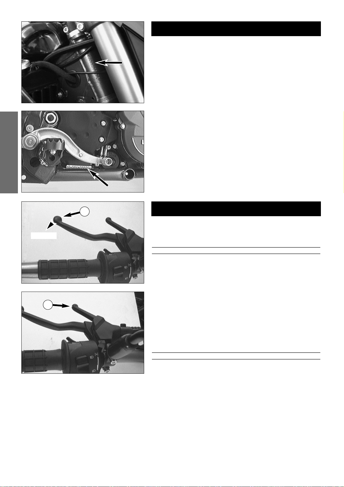
SERIAL NUMBER LOCATING . . . . . . . . . . . . . . . . . . . . . . .4
Frame number . . . . . . . . . . . . . . . . . . . . . . . . . . . . . . . .4
Engine number, engine type . . . . . . . . . . . . . . . . . . . . . .4
OPERATION INSTRUMENTS . . . . . . . . . . . . . . . . . . . . . . .4
Clutch lever . . . . . . . . . . . . . . . . . . . . . . . . . . . . . . . . . . .4
Hand decompression lever . . . . . . . . . . . . . . . . . . . . . . .4
Choke lever . . . . . . . . . . . . . . . . . . . . . . . . . . . . . . . . . . .5
Hand brake lever . . . . . . . . . . . . . . . . . . . . . . . . . . . . . . .5
Speedometer, tachometer . . . . . . . . . . . . . . . . . . . . . . . .5
Indicator lamps . . . . . . . . . . . . . . . . . . . . . . . . . . . . . . . .5
Ignition lock, steering lock . . . . . . . . . . . . . . . . . . . . . . . .6
Combination switch . . . . . . . . . . . . . . . . . . . . . . . . . . . .6
Starter tip switch, emergency OFF switch . . . . . . . . . . . .6
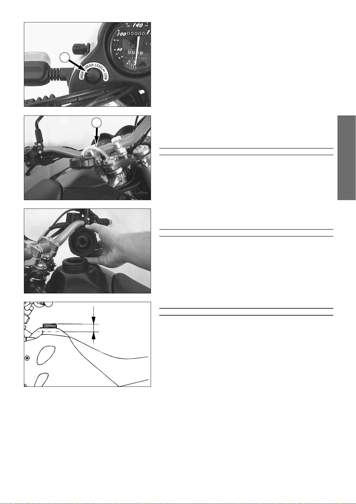
Headlight range adjustment . . . . . . . . . . . . . . . . . . . . . .7
Filler cap . . . . . . . . . . . . . . . . . . . . . . . . . . . . . . . . . . . . .7
Fuel . . . . . . . . . . . . . . . . . . . . . . . . . . . . . . . . . . . . . . . . .7
Fuel tap . . . . . . . . . . . . . . . . . . . . . . . . . . . . . . . . . . . . . .8
Hot start device . . . . . . . . . . . . . . . . . . . . . . . . . . . . . . . .8
Shift lever . . . . . . . . . . . . . . . . . . . . . . . . . . . . . . . . . . . .8
Kickstarter . . . . . . . . . . . . . . . . . . . . . . . . . . . . . . . . . . . .8
Foot brake pedal . . . . . . . . . . . . . . . . . . . . . . . . . . . . . . .8
Compression damping of fork . . . . . . . . . . . . . . . . . . . . .9
Rebound damping of fork . . . . . . . . . . . . . . . . . . . . . . . .9
Compression damping of shock absorber . . . . . . . . . . . .9
Rebound damping of shock absorber . . . . . . . . . . . . . . .9
Standard adjustment of fork and shock absorber . . . . . . .9
Helmet lock . . . . . . . . . . . . . . . . . . . . . . . . . . . . . . . . . .10
Passenger handles . . . . . . . . . . . . . . . . . . . . . . . . . . . . .10
DRIVING INSTRUCTIONS . . . . . . . . . . . . . . . . . . . . . . . . .11
LUBRICATION AND MAINTENANCE SCHEDULE . . . . . . .15
MAINTENANCE WORK ON CHASSIS AND ENGINE . . . . .16
Removing the seat . . . . . . . . . . . . . . . . . . . . . . . . . . . .16
Tool kit . . . . . . . . . . . . . . . . . . . . . . . . . . . . . . . . . . . . .16
Checking and adjusting the steering head bearing . . . .17
Changing the spring preload of the shock absorber . . . .17
Checking the rubber ring on the shock absorber . . . . . .18
Lubricate rear shock absorber link . . . . . . . . . . . . . . . . .18
Checking chain tension . . . . . . . . . . . . . . . . . . . . . . . . .18
Correcting chain tension . . . . . . . . . . . . . . . . . . . . . . . .18
Chain maintenance . . . . . . . . . . . . . . . . . . . . . . . . . . . .19
Chain wear . . . . . . . . . . . . . . . . . . . . . . . . . . . . . . . . . .19
Maintaining chain tension eccentrics . . . . . . . . . . . . . . .19
General information about disc brakes . . . . . . . . . . . . .20
Checking of brake fluid level - front brake . . . . . . . . . .20
Page
Refilling the front brake fluid reservoir . . . . . . . . . . . . .21
Checking the front brake pads . . . . . . . . . . . . . . . . . . .21
Replacing front brake pads . . . . . . . . . . . . . . . . . . . . . .21
Changing the basic position of the brake pedal . . . . . . .22
Checking the rear brake fluid level . . . . . . . . . . . . . . . .22
Refilling the rear brake fluid reservoir . . . . . . . . . . . . . .22
Checking the rear brake pads . . . . . . . . . . . . . . . . . . . .22
Replacing the rear brake pads . . . . . . . . . . . . . . . . . . . .22
Dismounting and mounting the front wheel . . . . . . . . .23
Dismounting and mounting the rear wheel . . . . . . . . . .24
Checking the shock absorption rubbers in the rear hub
. . .24
Tires, air pressure . . . . . . . . . . . . . . . . . . . . . . . . . . . . .24
Checking spoke tension . . . . . . . . . . . . . . . . . . . . . . . .25
Cooling system . . . . . . . . . . . . . . . . . . . . . . . . . . . . . . .25
Cooling liquid level check . . . . . . . . . . . . . . . . . . . . . . .26
Fuse / fan . . . . . . . . . . . . . . . . . . . . . . . . . . . . . . . . . . .26
Main fuse . . . . . . . . . . . . . . . . . . . . . . . . . . . . . . . . . . .26
Battery . . . . . . . . . . . . . . . . . . . . . . . . . . . . . . . . . . . . .27
Charging the battery . . . . . . . . . . . . . . . . . . . . . . . . . . .27
Removing the headlight mask . . . . . . . . . . . . . . . . . . . .28
Replacing the headlight lamp . . . . . . . . . . . . . . . . . . . .28
Replacing the instrument light . . . . . . . . . . . . . . . . . . . .28
Replacing the indicator lamps . . . . . . . . . . . . . . . . . . . .28
Cleaning the air filter . . . . . . . . . . . . . . . . . . . . . . . . . . .29
Adjusting idle speed . . . . . . . . . . . . . . . . . . . . . . . . . . .29
Adjusting the throttle cable . . . . . . . . . . . . . . . . . . . . . .29
Adjusting the choke cable . . . . . . . . . . . . . . . . . . . . . . .29
Adjusting the clutch cable . . . . . . . . . . . . . . . . . . . . . . .30
Checking the setting of the hand decompression cable .30
Oil circuit . . . . . . . . . . . . . . . . . . . . . . . . . . . . . . . . . . .30
Engine oil . . . . . . . . . . . . . . . . . . . . . . . . . . . . . . . . . . .31
Checking the engine oil level . . . . . . . . . . . . . . . . . . . . .31
Changing the engine oil and bleeding the oil system . . .31
Changing oil filter . . . . . . . . . . . . . . . . . . . . . . . . . . . . .32
Changing the fine screen filter . . . . . . . . . . . . . . . . . . .32
TROUBLE SHOOTING . . . . . . . . . . . . . . . . . . . . . . . . . . .33
CLEANING . . . . . . . . . . . . . . . . . . . . . . . . . . . . . . . . . . . .35
STORAGE . . . . . . . . . . . . . . . . . . . . . . . . . . . . . . . . . . . . .35
Re-initation after time of storage . . . . . . . . . . . . . . . . .35
TECHNICAL SPECIFICATIONS - CHASSIS . . . . . . . . . . . . .36
TECHNICAL SPECIFICATIONS - ENGINE . . . . . . . . . . . . . .37
NOTICES . . . . . . . . . . . . . . . . . . . . . . . . . . . . . . . . . . . . . .39
WIRING DIAGRAMM . . . . . . . . . . . . . . . . . . . . . . . . . . . .40
INDEX

ENGLISH
4
Frame number
The frame number is stamped on the right side of the steering head tube.
Write this number into the relevant box on page 1.
Engine number, engine type
The engine number and engine type are stamped on the right hand side of
the engine below the engine sprocket. Write the number into the box on
page no 1.
SERIAL NUMBER LOCATIONS
OPERATION INSTRUMENTS
Clutch lever
The clutch lever 1is fitted on the left hand side of the handle bar. When
engine is cold, there should be a play of 1-3 mm (0.04-0.1 in) (measured
at outer edge).
!
CAUTION
!
IF THERE IS NO PLAY ON THE CLUTCH LEVER, THE CLUTCH WILL START TO SLIP. THE
CLUTCH WILL THEN OVERHEAT, DESTROYING THE CLUTCH LININGS.
Hand decompression lever
The hand decompression lever 2is only used in two special cases:
a)When the engine stalled.
It is possible that the starter motor is not able to crank the engine on the
next attempt. This is due to the fact that the automatic decompressor
doesn’t work properly. If this happens, pull the manual decompression
lever and start again. Afterwards normal starting will be possible.
b) When you want to push the motorcycle.
While pushing, pull the hand decompression lever to make it easier to
get the engine going.
!
CAUTION
!
THE SETTING OF THE HAND DECOMPRESSION CABLE SHOULD BE REGULARLY CHECKED
(SEE MAINTENANCE WORK). A LACK OF PLAY IN THE HAND DECOMPRESSION LEVER CAN
RESULT IN ENGINE DAMAGE.
1–3 mm
1
2

ENGLISH
5
Choke lever
When the choke lever 1is pulled backwards, a bore is opened in the car-
buretor which enables the engine to draw in additional fuel. This produces
a „rich“ fuel/air mixture necessary for cold start. When the choke lever is
pushed forward as far as it will go, the bore will be closed again. In this
position the choke cable must have a play of approx. 2 mm.
!
CAUTION
!
IF THERE IS NO PLAY IN THE CHOKE CABLE, THE BORE OF THE COLD STARTER SYSTEM
CANNOT BE COMPLETELY CLOSED. THIS RESULTS IN HIGH FUEL CONSUMPTION, THE
ENGINE RUNS UNEVENLY WITH EXTREME WEAR OF PISTON AND CYLINDER.
Hand brake lever
The hand brake lever is mounted on the right side of the handlebar.
WARNING
IF THE RESISTANCE IN THE HAND BRAKE LEVER OR FOOT BRAKE PEDAL FEELS “SPONGY”
(NOT ENOUGH RESISTANCE), THIS IS AN INDICATION THAT SOMETHING IS WRONG WITH
THE BRAKE SYSTEM. DON’T RIDE YOUR MOTORCYCLE ANYMORE WITHOUT FIRST
HAVING THE BRAKE SYSTEM LOOKED OVER BY A KTM DEALER.
Speedometer, tachometer
The mileage indicator Ain the speedometer 2indicates overall mileage.
The day mileage indicator Bcan be set to 0 by means of the setting wheel
C. Turn the setting wheel forward until only zeros can be seen in the display.
The tachometer 3shows the engine speed in revolutions per minute (rpm).
Do not push the engine into the orange zone, which begins at 8500 rpm.
!
CAUTION
!
–M
AXIMUM RECOMMENDED ROTATION RATE IS 8500 RPM. ROTATION RATES EXCEE-
DING 8500 RPM WILL SHORTEN YOUR ENGINE’S LIFE. REFER ALSO TO THE SECTION
ON RUNNING IN
YOUR MOTORCYCLE TO BE FOUND IN THE
“D
RIVING
I
NSTRUC
-
TIONS
”
CHAPTER
.
–SPEEDOMETER AND TACHOMETER ARE NOT SUPPOSED TO GET IN CONTACT WITH
FUEL. WHIPE OFF SPLASHED FUEL ON THE PLASTIC PARTS IMMEDIATELY, OTHERWISE
THE PLASTIC PARTS MIGHT GET DAMAGED.
Indicator lamps
The red cooling liquid temperature warning lamp lights up as soon
as the cooling liquid has reached a temperature of approximately
110° C (230° F).
!
CAUTION
!
IF THE RED COOLING LIQUID TEMPERATURE WARNING LAMP LIGHTS UP WHILE
YOU ARE DRIVING, THE COOLING SYSTEM IS PROBABLY DEFECT. IMMEDIATELY
STOP THE ENGINE AND CHECK THE COOLING LIQUID LEVEL (SEE PAGE 26). DRI-
VING WITH THE WARNING LAMP ON WILL CAUSE ENGINE DAMAGE.
The green indicator lamp flashes when the flasher light is working in
the same rhythm as the flasher light. Faster flashing of the flasher
control lamp indicates a defect bulb
The blue indicator lamp lights up when the high beam is on.
The green indicator lamp lights up when the gear is switched to idle
(neutral).
1
23
A
B
C

ENGLISH
6
Ignition lock, steering lock
There are four positions to this lock. They are:
= ignition off, light off
= ignition on,– engine turned off: just parking light is on
– engine running: parking light and headlight on
= ignition off, light off, handlebar locked
!
CAUTION
!
BRIEFLY PRESS THE KEY IN THE POSITION IN ORDER TO TURN THE IGNITION
LOCK TO OR . THE HANDLEBAR CAN BE LOCKED BY TURNING IT FIRST
INTO THE EXTREME LEFT OR RIGHT POSITION AND THEN TURNING THE IGNITION
KEY TO THE POSITION.
IMPORTANT: Do not push the ignition key into the keyhole while
switching positions.
= ignition off, parking light on, handlebar locked
!
CAUTION
!
DO NOT LEAVE THE PARKING LIGHT ON FOR MORE THAN THREE HOURS WITH
THE ENGINE OFF. OTHERWISE YOU WILL NOT BE ABLE TO START THE ENGINE
WITH THE ELECTRIC STARTER.
ADDITIONALLY, THE BATTERY IS DISCHARGED BELOW THE NORMAL LEVEL AND
THEREBY DAMAGED. IN THIS CASE, THE BATTERY SHOULD BE RECHARGED AS
SOON AS POSSIBLE.
The ignition key can be removed in the positions , , and .
Combination switch
The rocker switch 1actuates the high beam and low beam.
= High-beam light
= Low-beam light
The switch 2returns to central position after actuation. Press flasher
switch towards switch housing to switch off the flasher.
= Flasher left
= Flasher right
The horn is sounded with button 3.
The light signal (high beam) is actuated with button 4.
NOTE: The engine must be running in order to be able to check that all
current consumers are functioning correctly.
Starter tip switch, emergency OFF switch
Use the starter tip switch 5to operate the electric starter.
!
CAUTION
!
MAXIMUM PERIOD FOR CONTINUOUS STARTING: 5 SECONDS. WAIT AT LEAST 5
SECONDS BEFORE TRYING AGAIN.
The emergency off switch 6is mainly a safety and emergency switch and
should normally be on.
If this symbol is visible on the switch, the engine can be started (i.e.
the ignition circuit and the starter circuit are switched on).
If this symbol is visible on the switch, the engine can not be started
(i.e. the ignition circuit and the starter circuit are interrupted).
1
2
3
5
6
P
P
P
P
1
4

ENGLISH
7
Headlight range adjustment
The headlight beam must be adjusted to the current load (i.e. with/without
passenger).
The adjustment can be performed very easily by means of the setting
wheel 1on the cockpit.
Turn clockwise to reduce the range of the headlights.
Turn counterclockwise to increase the range of the headlights.
Filler cap
To open: Pull the tank venting hose 2out if the steering head and turn
the filler cap anti-counterclockwise.
To close: Screw on the filler cap clockwise. Place the tank venting hose in
the steering head, avoiding any kinks.
!
CAUTION
!
USE ONLY UNLEADED PREMIUM GRADE GASOLINE (95 OCTANES). NEVER USE ANY
GASOLINE HAVING LESS THAN 95 OCTANES BECAUSE IT MAY DAMAGE THE ENGINE.
Fuel
The LC4 engine needs premium gasoline with an octane number of 95 or
higher. !
CAUTION
!
–U
SE ONLY UNLEADED PREMIUM GRADE GASOLINE (95 OCTANES). NEVER USE ANY
GASOLINE HAVING LESS THAN 95 OCTANES BECAUSE IT MAY DAMAGE THE ENGINE.
Fuel expands when its temperature rises. Therefore do not fill the tank to
the top (see fig.).
WARNING
GASOLINE IS HIGHLY FLAMMABLE AND POISONOUS. EXTREME CAUTION SHOULD BE
USED WHEN HANDLING GASOLINE. DO NOT REFUEL THE MOTORCYCLE NEAR OPEN FLA-
MES OR BURNING CIGARETTES. ALWAYS SWITCH OFF THE ENGINE BEFORE REFUELLING.
BE CAREFUL NOT TO SPILL GASOLINE ON THE ENGINE OR EXHAUST PIPE WHILE THE
ENGINE IS HOT. WIPE UP SPILLS PROMPTLY. IF GASOLINE IS SWALLOWED OR SPLASHED
IN THE EYES, SEEK A DOCTOR’S ADVICE IMMEDIATELY.
35 mm
2
1

ENGLISH
8
Fuel tap
OFF
In this position the fuel tap is closed. No fuel may flow to the carburetor.
ON When using the motorcycle, the twist grip must be set to the ON
position. Now fuel may flow to carburetor. In this position the tank
empties down to the fuel reserve of approx. 1.5 liters.
RES The reserve, approximately 1.5 liters, cannot be tapped until the twist
grip is turned to the RES position. Fill the tank as soon as possible and
remember to turn the twist grip back to the ON position so that you
will have backup fuel next time, too.
!
CAUTION
!
THE FUEL TAP SHOULD BE LOCKED WHENEVER THE MOTORCYCLE IS PARKED. IF THE TAP
IS NOT CLOSED THE CARBURETOR MAY OVERFLOW AND FUEL CAN GET INTO THE
ENGINE.
Hot start device
The carburetor is equipped with a hot start device which makes it easier to
start the engine when hot. Press the hot start button 1until it engages.
This will slightly lift the throttle slide. Once the engine is running, pull the
hot start button back into its original position.
NOTE:
Always pull the hot start device back into the initial position as soon as the
engine is running. An activated hot start device will have a negative impact
on the cold starting properties of the engine.
Shift lever
The shift lever is mounted on the left side of the engine. The position of
the gears is shown in the illustration. Neutral, or the idle speed, is located
between first and second gear.
Kickstarter
The kickstarter is mounted on the left side of the engine. The upper part
can be swivelled.
WARNING
T
O AVOID INJURIES
,
IT IS RECOMMENDED TO WEAR BOOTS WHEN USING THE KICKSTARTER
.
Foot brake pedal
The foot brake pedal is located in front of the right footrest. The basic posi-
tion can be adjusted to the seat position (see maintenance work).
WARNING
IF THE RESISTANCE IN THE HAND BRAKE LEVER OR FOOT BRAKE PEDAL FEELS “SPONGY”
(NOT ENOUGH RESISTANCE), THIS IS AN INDICATION THAT SOMETHING IS WRONG WITH
THE BRAKE SYSTEM. DON’T RIDE YOUR MOTORCYCLE ANYMORE WITHOUT FIRST
HAVING THE BRAKE SYSTEM LOOKED OVER BY A KTM DEALER.
N
O
O
F
F
R
E
S
F
U
E
L
N
O
O
F
F
R
E
S
F
U
E
L
N
O
O
F
F
R
E
S
F
U
E
L
OFF ON RES
1
2,3,4,5
1
N

ENGLISH
9
Compression damping of fork
The compression damping „COM“ (Compression) is mounted in the right
fork tube. It only regulates the degree of damping during compressing.
With the knob 1the degree of damping of the compression can be adju-
sted. Turn the knob clockwise to increase damping, turn it counterclock-
wise to reduce damping during compressing.
BASIC ADJUSTMENT:
Turn the adjuster knob clockwise until it stops, than turn the knob 14 clicks
counterclockwise.
Rebound damping of fork
The rebound damping „REB“ (Rebound) is mounted in the left fork tube. It
only regulates the degree of damping during rebounding.
With the knob 2the degree of damping of the rebound can be adjusted.
Turn the knob clockwise to increase damping, turn it counterclockwise to
reduce damping during rebounding.
BASIC ADJUSTMENT:
Turn the adjuster knob clockwise until it stops, than turn the knob 14 clicks
counterclockwise.
Compression damping of shock absorber
With the knob 3the degree of damping of the compression can be adju-
sted to 7 positions. Turn the knob counterclockwise to increase damping,
turn it clockwise to reduce damping during rcompressing.
STANDARD ADJUSTMENT: position 3
Rebound damping of shock absorber
With the setting wheel 4the degree of damping of the rebound can be
adjusted to 11 positions. Turn the knob to the left side to increase dam-
ping, turn it to the right side to reduce damping during rebounding.
STANDARD ADJUSTMENT: position 5
WARNING
–NEVER CHANGE DAMPING BETWEEN THE TEST DRIVES MORE THAN 2 CLICKS.
–T
HE DAMPING UNIT OF THE SHOCK ABSORBER IS FILLED WITH HIGHLY COMPRESSED
NITROGEN. NEVER TRY TO TAKE THE SHOCK ABSORBER APART OR TO DO ANY MAIN-
TENANCE WORK YOURSELF. SEVERE INJURIES COULD BE THE RESULT.
3
4
Change the shock absorber preload see page 17.
STANDARD ADJUSTMENT FORK SHOCK ABSORBER
compression rebound compression rebound preload
without passenger, driver appr. 75 kg (166 lb) 14 14 3 5 23
with passenger 14 14 5 3 28
1
2

ENGLISH
10
Helmet lock
The helmet lock 1is located behind the right side cover. To unlock it, ins-
ert ignition key and turn it clockwise. Hang helmet on rod, turn key coun-
terclockwise as far as it goes.
WARNING
NEVER LEAVE YOUR HELMET ATTACHED TO HELMET LOCK WHEN RIDING YOUR
MOTORCYCLE BECAUSE THE HELMET CAN GET CAUGHT IN THE REAR WHEEL AND THROW
THE VEHICLE OUT OF CONTROL.
Passenger handles
On the tail of the motorcycle you will find two handles which a passenger
can use to hold on to.
1

ENGLISH
11
DRIVING INSTRUCTIONS
Instructions for initial operation
– Verify that your KTM dealer performed the PREPARATION
OF VEHICLE jobs (see Customer Service Manual).
– Read the entire manual carefully before your first drive.
– Familiarize yourself with the operating elements.
– Adjust the foot brake pedal and the hand brake lever to the
most comfortable positions for you.
– Get used to handling the motorcycle on an empty car park,
before starting on a longer drive. Also try to drive as slowly
as possible and in standing position, to improve your feeling
for the vehicle.
– Hold the handlebar with both hands and leave your feet on
the foot rests while driving.
– Remove your foot from the foot brake pedal when you are
not braking. If the foot brake pedal is not released the brake
pads rub continuously and the braking system is overheated.
– You may only be accompanied by a passenger if your
motorcycle is fitted and registered for such purposes. The
passenger must hold tight to the brackets or hold on to the
driver during the drive, with his feet on the passenger foot
rests.
– Do not make any alterations to the motorcycle and always
use ORIGINAL KTM SPARE PARTS. Spare parts from other
manufacturers can impair the safety of the motorcycle.
– Motorcycles are sensitive to alterations in the distribution of
weight. If you are taking luggage with you, this should be
secured as close as possible to the middle of the vehicle; dis-
tribute the weight evenly between the front and rear wheel.
Never exceed the maximum permissible laden weight and
the axle weights. The maximum permissible laden weight is
made up of the following components:
– Motorcycle ready for operation and tank full
– Luggage
–
Driver and passenger with protective clothing and helmet.
– Pay attention to running in instructions.
Running in
Even finely machined surfaces of engine parts have rougher
surfaces than parts that slide on each other for a long time.
Therefore, every engine must be run in. For this reason, do not
demand maximum performance from the engine for the first
100 kilometers. The vehicle must be run in at low, changing
performance level for the first 1000 KM (620 miles). The maxi-
mum number of revolutions per minute must not go exceed
4800 rpm. Once you have run your engine in for 1000 km
(620 mi), you may push it to its 8500 rpm limit , i.e. up to the
orange zone indicated in the tachometer. Exceeding the above
listed rotations as well as pushing high rpm when the engine is
cold will have an adverse effect on the life of your engine.
NOTE:
During the stage of running the engine in, that is the first 1000
KM (620 miles), the engine oil used should be of a mineral oil
formula. This also applies if the engine has been repaired.
Check the following before each start
When you start off, the motorcycle must be in a perfect tech-
nical condition. For safety reasons, you should make a habit of
performing an overall check of your motorcycle before each
start.
The following checks should be performed:
1 CHECK THE OIL LEVEL
Insufficient oil results in premature wear and consequently
to engine damage.
2 FUEL
Check that there is sufficient fuel in the tank; when closing
the filler cap, check that the tank venting hose is free of
kinks.
3 CHAIN
A loose chain can fall off; an extremely worn chain can tear,
and insufficient lubrication can result in unnecessary wear to
the chain and rear sprockets.
4 TIRES
Check for damaged tires. Tires showing cuts or dents must
be replaced. The tread depth must comply with the legal
regulations. Also check the air pressure. Insufficient tread
and incorrect air pressure reduce the driving performance.
5 BRAKES
Check correct functioning of the braking system. Check for
sufficient brake fluid in the reservoir. If the level of brake
fluid falls below the minimum value, this indicates a leak in
the braking system or completely worn out brake pads.
Arrange for the braking system to be checked by a KTM
specialist garage, as complete failure of the braking system
can be expected.
Also check the state of the brake hoses and the thickness of
the brake linings. Brake linings measured at their thinnest
point should not be less than 1 mm since extremely worn
linings can lead to brake failure.
6 CABLES
Check correct setting and easy running of all control cables.
7 COOLING LIQUID
Check the level of cooling liquid when the engine is cold.
8 ELECTRICAL SYSTEM
Check correct functioning of headlamps, parking light, tail-
light, brake light, flashers, indicator lamps and horn while
the engine is running.
9 LUGGAGE
If you are taking luggage with you, check that this is secu-
rely fastened.
WARNING
–W
EAR SUITABLE CLOTHING WHEN DRIVING A MOTORCYCLE. CLEVER
KTM DRIVERS ALWAYS WEAR A HELMET, BOOTS, GLOVES AND A
JACKET, REGARDLESS OF WHETHER DRIVING ALL DAY OR JUST FOR A
SHORT TRIP. THE PROTECTIVE CLOTHING SHOULD BE BRIGHTLY
COLOURED SO THAT OTHER USERS OF THE ROADS CAN SEE YOU AS
EARLY AS POSSIBLE. YOUR PASSENGER OF COURSE WILL ALSO NEED
SUITABLE PROTECTIVE CLOTHING.
–D
O NOT DRIVE AFTER HAVING CONSUMED ALCOHOL.
–O
NLY USE ACCESSORIES THAT HAVE BEEN RELEASED BY KTM. FOR
EXAMPLE, FRONT PANELLING CAN IMPAIR THE DRIVING PROPERTIES OF
THE MOTORCYCLE. CASES, EXTRA TANKS ETC. CAN ALTER THE WEIGHT
DISTRIBUTION AND THUS ALSO IMPAIR THE VEHICLE’S DRIVING PRO-
PERTIES.
–T
HE FRONT AND REAR WHEEL ARE ONLY ALLOWED TO BE TIRED WITH
TIRES THAT HAVE THE SAME PROFILE TYPE.

ENGLISH
12
Starting when the engine is cold
1 Open the fuel tap.
2 Turn on the ignition (ignition key position: ).
3 Switch the gear to neutral (green lamp 1lights).
4 Switch on the emergency off switch (symbol 2must be visible).
5 Operate the choke lever 3.
6 Operate the starter tip switch 5without accelerating.
7 If the engine starts, push the choke lever back a little bit, as soon as the
engine runs unevenly.
8 Swing up the sidestand 4.
WARNING
DO NOT START THE ENGINE AND ALLOW IT TO IDLE IN A CLOSED ROOM. EXHAUST
FUMES ARE POISONOUS AND CAN CAUSE LOSS OF CONSCIOUSNESS AND DEATH.
ALWAYS PROVIDE ADEQUATE VENTILATION WHILE THE ENGINE IS RUNNING.
!
CAUTION
!
–M
AXIMUM PERIOD FOR CONTINUOUS STARTING: 5 SECONDS. WAIT AT LEAST 5
SECONDS BEFORE TRYING AGAIN.
–D
ON’T RIDE YOUR MOTORCYCLE WITH FULL LOAD AND DON’T REV ENGINE WHEN
COLD. BECAUSE THE PISTON IS WARMING UP FASTER THAN THE WATER COOLED
CYLINDER, IT CAN CAUSE ENGINE DAMAGE. ALWAYS KEEP IN MIND THAT THE ENGINE
SHOULD BE WARMED UP WITH SMALL LOAD AT MEDIUM R.P.M.
IF THE ENGINE IS DOES NOT CRANK WHEN YOU ACTUATE THE STAR-
TER TIP SWITCH:
– Check if the ignition is on
– Check if the gear is switched to neutral
– Check if the emergency off switch is on
– Check if the parking light and the cockpit lights are on.
– If this is not the case, the battery is discharged and the engine can be
started with the kickstarter (see starting with an empty battery).
– If the lights are on, proceed as described in the „Trouble-shooting“
section or contact a KTM dealer.
WARNING
T
O AVOID INJURIES
,
IT IS RECOMMENDED TO WEAR BOOTS WHEN USING THE KICKSTARTER
.
IF THE ENGINE CRANKS BUT DOES NOT START, WHEN YOU ACTUATE
THE STARTER TIP SWITCH:
– Check if the fuel tap is open
– Check if the choke lever has been operated
– Check if sufficient fuel is in the tank
– If this is not the case, refill the tank
– if sufficient fuel is in the tank, proceed as described in the „Trouble-
shooting“ section or contact a KTM dealer.
THE ELECTRIC STARTER DOESN’T CRANK THE ENGINE WHEN THE
STARTER TIP SWITCH IS OPERATED EVEN THOUGH SUFFICIENT ELEC-
TRIC CURRENT IS AVAILABLE:
– Pull the hand decompression lever 6, start and release the lever.
NOTE:
Side stand models are equipped with a safe-starting system. With the side
stand on the ground, the engine can only be started with the transmission
in neutral position. The engine stops if a gear is engaged before swinging
up the side stand.
Starting when the engine is warm
1 Open the fuel tap.
2 Turn on the ignition (ignition key position: ).
3 Switch the gear to neutral (green lamp 1lights).
4 Switch on the emergency off switch (symbol 2must be visible).
5 Operate the starter switch 5without accelerating.
6 Swing up the sidestand 4.
2
5
3
6
1
4

ENGLISH
13
Starting when the engine is hot
1 Open the fuel tap.
2 Turn on the ignition (ignition key position: ).
3 Switch the gear to neutral (green lamp 1lights).
4 Switch on the emergency off switch (symbol 2must be
visible).
5 Operate the hot start button at the carburetor.
6 Operate the starter switch 5without accelerating.
7 Once the engine is running, pull hot start device back into
its basic position
8 Swing up the sidestand 4.
What to do when the engine is „flooded”
The throttle must be fully opened when starting.
Kickstart instructions
Start as described above, then push the kickstarter hard all the way.
WARNING
ALWAYS WEAR BOOTS WHEN USING THE KICKSTARTER TO AVOID INJURY.
Starting with an empty battery
When the battery of the motorcycle is empty the engine can
only startet by disconnecting the power supply of the head
light. For this purpose a pin and socket connector 7can be
fund below the headlight mask. Disconnect the pin and socket
connector and start the engine with the kickstarter.
!
CAUTION
!
AS SOON AS THE ENGINE IS RUNNING RECONNECT THE PIN AND SOCKET
CONNNECTOR TO MAKE SURE THE HEAD LIGHT IS WORKING.
Starting off
Pull the clutch lever. Put the engine into first gear, slowly
release the clutch lever and open throttle at the same time.
WARNING
B
EFORE YOU START OFF
,
CHECK THAT THE SIDE STAND HAS BEEN SWUNG
RIGHT UP TO THE TOP
. I
F THE STAND DRAGS ON THE GROUND
,
THE
MOTORCYCLE CAN GO OUT OF CONTROL
.
!
CAUTION
!
–H
IGH RPM RATES WHEN THE ENGINE IS COLD HAVE AN ADVERSE
EFFECT ON THE LIFE OF YOUR ENGINE. WE RECOMMEND YOU RUN
THE ENGINE IN A MODERATE RPM RANGE FOR A FEW MILES GIVING IT
A CHANCE TO WARM UP. AFTER THAT NO FURTHER PRECAUTIONS IN
THIS RESPECT NEED BE TAKEN.
–S
HIFT TO THE NEXT HIGHER GEAR BY 8500 RPM AT THE LATEST.
–
N
EVER HAVE THE THROTTLE WIDE OPEN WHEN CHANGING DOWN TO A
LOWER GEAR
. T
HE ENGINE WILL OVERSPEED
,
DAMAGING THE VALVES
.
I
N ADDITION
,
THE REAR WHEEL BLOCKS SO THAT THE MOTORCYCLE
CAN EASILY GET OUT OF CONTROL
.
–
L
ONG WHEELIE DRIVING CAUSES THE OIL PRESSURE TO DROP
. T
HE OIL
PRESSURE WILL AUTOMATICALLY INCREASE AS SOON AS YOU DRIVE ON
NORMALLY
. D
OING WHEELIES FOR A LONG TIME WILL DAMAGE YOUR
ENGINE
.
–I
F THE RED COOLING LIQUID TEMPERATURE LAMP LIGHTS UP WHILE
YOU ARE DRIVING, THIS INDICATES COOLING SYSTEM TROUBLE. IMME-
DIATELY STOP AND TURN OFF THE ENGINE. DRIVING WITH THE WAR-
NING LAMP ON WILL CAUSE ENGINE DAMAGE.
– PLACE A CLOTH ON THE RADIATOR CAP. OPEN THE CAP SLOWLY,
SO THE EXCESS PRESSURE IN THE COOLING SYSTEM CAN ESCAPE. -
CAUTION SCALDING HAZARD! - AND CHECK THE COOLING
LIQUID LEVEL.
–
DO NOT DRIVE ON, UNTIL THERE IS SUFFICIENT LIQUID IN THE COO-
LING SYSTEM. HOWEVER, CALL ON ONE OF KTM’S DEALERS AS
SOON AS POSSIBLE IN ORDER TO HAVE THE DEFECT REMEDIED.
–I
F ANY ABNORMAL VIBRATIONS OCCUR WHILE DRIVING, CHECK THAT
THE ENGINE FASTENING SCREWS ARE TIGHT.
–I
N THE EVENT THAT, WHILE RIDING YOUR MOTORCYCLE, YOU NOTICE
ANY UNUSUAL OPERATION-RELATED NOISE, STOP IMMEDIATELY, TURN
THE ENGINE OFF, AND CONTACT AN AUTHORIZED KTM DEALER.
Shifting/Riding
You are now in first gear, refered to as the drive or uphill gear.
Depending on the conditions (traffic, road gradient, etc.), you
can shift to a higher gear. Close throttle, at the same time pull
clutch lever and shift to the next higher gear. Let clutch lever
go again and open throttle. If you turned on the choke, make
sure you turn it off again as soon as engine is warm.
When you reach full speed through turning the throttle grip all
the way, turn throttle back to 3/4; the speed hardly decreases
although the engine will use less gas. Never open the throttle
wider than the engine can handle. Excessive turning of the
throttle grip will increase full consumption.
By shifting down, use the brakes if necessary and close throttle
at the same time. Pull clutch lever and shift down to the next
gear. Let clutch lever go slowely and open throttle or shift
down again.
If the engine is killed f.ex. at a crossing, simply pull the clutch
lever and start. It is not necessary to switch the gear to NEUTRAL.
WARNING
–OBSERVE THE TRAFFIC REGULATIONS, DRIVE DEFENSIVELY AND TRYING
TO LOOK AHEAD AS FAR AS POSSIBLE SO THAT ANY HAZARDS CAN BE
RECOGNIZED AS EARLY AS POSSIBLE.
–ADJUST YOUR DRIVING SPEED ACCORDING TO THE CONDITIONS AND
YOUR DRIVING SKILLS.
–D
RIVE CAREFULLY ON UNKNOWN ROADS
–N
EVER LEAVE A HELMET ATTACHED TO HELMET LOCK WHEN RIDING
YOUR MOTORCYCLE BECAUSE THE HELMET CAN GET CAUGHT IN THE
REAR WHEEL AND THROW THE VEHICLE OUT OF CONTROL.
–REPLACE THE HELMET VISOR RESPECTIVELY GOGGLE GLASSES IN PLENTY
OF TIME. WHEN LIGHT SHINES DIRECTLY ON SCRATCHED VISOR OR
GOGGLES, YOU WILL BE PRACTICALLY BLIND.
–AFTER FALLING WITH THE MOTORCYCLE, CHECK ALL FUNCTIONS
THOROUGHLY BEFORE STARTING UP OPERATIONS AGAIN.
7

ENGLISH
14
Stopping and parking
Apply the brakes fully and put the engine into neutral. To stop the engine,
switch off the ignition. Close fuel tap. Park on solid ground and lock the
vehicle.
WARNING
–N
EVER LEAVE YOUR MOTORCYCLE WITHOUT SUPERVISION AS LONG AS THE ENGINE
IS RUNNING.
–M
OTORCYCLE ENGINES PRODUCE A GREAT AMOUNT OF HEAT WHILE RUNNING. THE
ENGINE RADIATORS, EXHAUST, EXHAUST SYSTEM, BRAKE DISCS, AND SHOCK ABSOR-
BERS CAN BECOME VERY HOT. DO NOT TOUCH ANY OF THESE PARTS AFTER OPERA-
TING THE MOTORCYCLE, AND TAKE CARE TO PARK IT WHERE PEDESTRIANS ARE NOT
LIKELY TO TOUCH IT AND GET BURNED.
–NEVER PARK YOUR MOTORCYCLE IN PLACES WHERE THERE EXIST FIRE HAZARDS DUE
TO DRY GRASS OR OTHER EASILY FLAMMABLE MATERIALS.
!
CAUTION
!
–P
ARK YOUR MOTORCYCLE, SO THAT IT RESTS STABLY ON THE SIDESTAND (HARD
GROUND, LEVEL SURFACE) AND CAN’T TIP OVER.
–DO NOT LEAVE THE PARKING LIGHT ON FOR MORE THAN THREE HOURS WITH THE
ENGINE OFF. OTHERWISE YOU WILL NOT BE ABLE TO START THE ENGINE WITH THE
ELECTRIC STARTER.
–CLOSE THE FUEL TAP WHEN LEAVING YOUR VEHICLE.OTHERWISE THE CARBURETOR
CAN OVERFLOW AND FUEL WILL ENTER THE ENGINE.
–A
LWAYS TAKE OUT THE IGNITION KEY WHEN PARKING YOUR MOTORCYCLE SO THAT
IT CANNOT BE USED BY UNAUTHORIZED PERSONS.
NOTE REGARDING THE SIDE STAND:
Use your foot to kick side stand forward up to the stop and lean the
motorcycle sideways. Make sure that the ground is solid and that your
motorcycle is standing securely. Just in case, you can shift into first gear.
!
CAUTION
!
THE SIDE STAND IS DESIGNED TO BEAR ONLY THE LOAD OF THE MOTORCYCLE. THE SIDE
STAND AND/OR THE FRAME CAN BE DAMAGED AND THE MOTORCYCLE CAN FALL OVER IF
YOU MOUNT THE MOTORCYCLE, THUS PUTTING AN ADDITIONAL LOAD ON THE SIDE STAND.
Braking
Close throttle and apply the hand and foot brakes at the same time. When
driving on sandy, wet or slippery ground use mainly the rear wheel brake.
Always brake with feeling, blocking wheels can cause you to skid or fall.
Also change down to lower gears depending on your speed.
When driving downhill, use the braking effect of the engine. Change down
one or two gears but do not overspeed the engine. In this way, you will not
need to brake so much and the brakes will not overheat.
WARNING
WHEN YOU BRAKE, THE BRAKE DISCS, BRAKE PADS, BRAKE CALIPER AND BRAKE FLUID
HEAT UP. THE HOTTER THESE PARTS GET, THE WEAKER THE
BRAKING EFFECT. IN EXTREME
CASES, THE ENTIRE BRAKING SYSTEM CAN FAIL.

ENGLISH
15
Check engine oil level
Change engine oil
Clean oil screen and magnet of the drain plugs whenever you exchange the engine oil
Change oil filter insert
Change fine screen filter (screwed filter) at front pipe (of the frame)
Check oil lines for leakage and proper instalment without kinks
Check valve clearance
Clean spark plug and adjust electrode gap
Change spark plug after 10 000 kilometers (6 200 miles)
Check ignition point
Drain and clean carburetor float chamber
Adjust idling
Check breather hoses of engine gase and gas tank for correct position without buckles
Clean air filter and air filter box
Check sprockets, chain guides and chain for wear
Maintain chain tension eccentrics (Duke)
Clean and lube chain
Check chain tension
Check cooling liquid level
Check quality of antifreezer
Check cooling system for leaks – visual check
Check exhaust system for leakage
Check exhaust brackets
Disassemble and clean spark arrestor discs (USA models)
Check brake fluid level front and rear
Change brake fluid
Check brake pad thickness
Check brake discs
Check condition and correct instalment of brake hoses
Check free play and easy operation of foot brake pedal
Check adjustment and function of telescopic fork
Check telescopic fork for leaks
Change telescopic fork oil
Perform a full maintenance job for the telescopic fork
Clean dust scrabber of telescopic fork
Check steering head bearing clearance / adjust
Clean and grease steering head bearings and its seals
Check adjustment and funktion of shock absorber
Check O-ring of the shock absorber for wear
Service the shock absorber
Grease nipple of the Pro Lever suspension system
Disassemble the Pro Lever suspension system linkage and perform a full maintenance job on it
Service swingarm pivot
Check spoke tension and join
Check wheel bearings for clearance
Check shock absorber rubbers on the rear hub
Check tire condition and air pressure
Check cables for damage and easy working
Lube and adjust cables
Check the electrical system
Check battery holder, battery and connections
Check adjustment of headlight
Spray ignition lock, emergency off switch, and light switch with contact spray
Check all screws, nuts and hose clamps for proper tightness
Grease or lube all pivot points and sliding points
PERIODIC MAINTENANCE SCHEDULE
before each start
after washing
1st service, after
500 km (300 miles)
after 2500 km
(1500 miles)
after 5000 km
(3000 miles) or
once a year
at least once a year
KTM
rider KTM
dealer
IF THE MOTORCYCLE IS USED FOR COMPETITIVE RACING, THE 5000 KM
(3000 MILES) SERVICE NEEDS TO BE CARRIED OUT AFTER EVERY RACE
Duke 2.98

ENGLISH
16
Removing the seat
The seat is provided with a quick-locking mechanism and can therefore be
removed very easily. Turn the quick-locking mechanism 1on the under-
side of the fender 180° counterclockwise and lift the rear section of the
seat. Pull the seat backwards and unhook it where it is held by the oval
head screw 2.
Mounting the seat:
– Hook the seat onto the oval head screw 2.
– Slide it forward to let the retaining bracket 3engage in the seat.
– Press the quick-locking mechanism upward and turn it 180° clockwise.
Tool set
The tool set 4is located in the tool box under the right side cover.
WARNING
ALL MAINTENANCE AND ADJUSTEMENT OPERATIONS THAT ARE MARKED WITH A * REQUIRE SPECIALIST KNO-
WLEDGE. FOR YOUR OWN SAFETY, LET THESE TASKS BE CARRIED OUT BY A KTM-DEALER
!
CAUTION
!
–W
HEN CLEANING THE MOTORCYCLE, DO NOT USE A HIGH PRESSURE CLEANING UNIT IF POSSIBLE, OTHERWISE WATER WILL PENETRATE THE BEARINGS,
CARBURETOR, ELECTRIC CONNECTORS ETC.
–W
HEN TRANSPORTING YOUR KTM, ENSURE THAT IT IS HELD UPRIGHT WITH RESTRAINING STRAPS OR OTHER MECHANICAL FASTENING DEVICES. IFTHE
MOTORCYCLE SHOULD FALL OVER, FUEL CAN LEAK FROM THE CARBURETOR OR FUEL TANK
–DO NOT USE TOOTHED WASHERS OR SPRING WASHERS WITH THE ENGINE FASTENING SCREWS, AS THESE WORK INTO THE FRAME PARTS AND KEEP WOR-
KING LOOSE. INSTEAD, USE SELF-LOCKING NUTS.
–L
ET YOUR MOTORCYCLE COOL DOWN BEFORE BEGINNING ANY MAINTENANCE WORK IN ORDER TO AVOID GETTING BURNED.
–D
ISPOSE OF OIL, GREASE, FILTERS, FUELS, CLEANING AGENTS ETC. ACCORDING TO YOUR LOCAL REGULATIONS.
–U
NDER NO CIRCUMSTANCES MAY USED OIL BE DISPOSED OF IN THE SEWAGE SYSTEM OR IN THE OPEN COUNTRYSIDE. 1 LITER USED OIL CONTAMINATES
1.000.000 LITERS WATER.
MAINTENANCE WORK ON CHASSIS AND ENGINE
1
2
3
1
4

ENGLISH
17
Checking and adjusting the steering head bearing*
Check steering head bearing for play periodicaly. To check this, put
motorcycle on stand so that the front wheel is off the ground. Now try to
move the fork forward
and backward - no play should be discernable To
adjust, loosen the five clamp screws
1of the top triple clamp and turn stee-
ring stem bolt clockwise 2until there is no more play. Don’t tighten the
steering stem bolt all the way, otherwise the bearings will be damaged.
With a plastic hammer, lightly tap on the top triple clamp to release ten-
sion. Re-tight the five clamp screws to 25 Nm (18 ft.lb).
WARNING
I
F THE STEERING HEAD BEARING IS NOT ADJUSTED TO BE FREE OF PLAY
,
THE MOTORCYCLE
WILL SHOW AN UNSTEADY DRIVING PERFORMANCE AND CAN GET OUT OF CONTROL
.
!
CAUTION
!
IF YOU DRIVE WITH PLAY IN THE STEERING HEAD BEARING FOR LONGER PERIODS, FIRSTLY
THE BEARINGS AND THEN THE BEARING SEATS IN THE FRAME WILL BE DESTROYED.
At least once a year, the steering head bearings should be greased.
Changing the spring preload of the shock absorber
KTM sets the shock absorber for a driver only, weighing approximately 75
kg (165 lb). If you want to take a passenger with you, of if you weigh con-
siderably more or less than 75 kg (165 lb), you should change the spring
preload accordingly. This is easily done.
NOTE:
– Before changing the spring preload note down the basic setting, e.g.
how many threads are visible above the adjusting ring.
– One rotation of the adjusting ring 5changes the spring preload by
approximately 2 mm.
Loosen the allan head screw 4at the adjustment ring 5. Use the special
wrench 6from the tool set to turn the adjusting ring as required. Place the
adjusting ring in a suitable position, and tighten the allan head screw.
ADJUSTMENT VALUES - SPRING PRELOAD:
Minimum preload...............................................................10 mm
Preload driver only 75 kg BASIC SETTING..........................23 mm
Preload with passenger.......................................................28 mm
A = spring preload
1
2
5
6
A
4

ENGLISH
18
Checking the rubber ring on the rear shock absorber
A rubber ring mounted on the rear shock absorber serves as a vibration
damper. This ring gets pressed together with time and loses its shock
absorbing quality.
Measure the distance between the two discs at various points around their
circumferences. The space should be at least 2.5 mm wide. Have the rub-
ber ring replaced in a KTM garage when compaction due to wear has
exceeded the limit.
!
CAUTION
!
N
OT REPLACING THE RUBBER RING IN TIME CAN RESULT IN DAMAGE TO THE SHOCK
ABSORBER
.
WARNING
THE DAMPING UNIT OF THE SHOCK ABSORBER IS FILLED WITH HIGHLY COMPRESSED
NITROGEN. NEVER TRY TO TAKE THE SHOCK ABSORBER APART OR TO DO ANY MAINTE-
NANCE WORK YOURSELF. SEVERE INJURIES COULD BE THE RESULT.
Lubricating the shock absorber linkage
The bearings in the rocker arm must be greased in regular intervals. For this
purpose, a grease nipple 1is mounted on the rocker arm.
!
CAUTION
!
AFTER EACH TIME THE MOTORCYCLE IS WASHED, IT IS ESPECIALLY IMPORTANT TO
GREASE THE GREASE NIPPLE TO PUSH ANY WATER OUT OF THE BEARINGS.
Checking chain tension
To check chain tension, turn off the engine and shift into neutral. Chain
tension is correct when the chain can just barely be pushed up to touch the
swingarm at the level of the screw 2(see illustration). If necessary, correct
chain tension.
WARNING
–I
F CHAIN TENSION IS TOO GREAT, PARTS WITHIN THE SECONDARY POWER TRANSMIS-
SION (CHAIN, CHAIN SPROCKETS, TRANSMISSION AND REAR WHEEL BEARINGS) WILL
BE SUBJEC
TED TO UNNECESSARY STRESS, RESULTING IN PREMATURE WEAR AND EVEN
CHAIN BREAKAGE.
–TOO MUCH SLACK IN THE CHAIN, ON THE OTHER HAND, CAN RESULT IN THE CHAIN
JUMPING OFF THE CHAIN WHEELS. IF THIS HAPPENS, THE CHAIN COULD ALSO BLOCK
THE REAR WHEEL OR DAMAGE THE ENGINE.
–I
N EITHER CASE THE OPERATOR IS LIKELY TO LOSE CONTROL OF THE MOTORCYCLE.
Correcting chain tension
– Loosen hexagon nuts 3on the left and right swingarm fists.
– Loosen allan head screw 4.
– Turn wheel spindle and eccentrics counterclockwise.
!
CAUTION
!
IF THE WHEEL SPINDLE BECOMES LOOSENED DURING THE PROCESS, RETURN ECCEN-
TRICS TO THEIR ORIGINAL POSITION BEFORE RETIGHTENING THE WHEEL SPINDEL (SEE
MAINTAINING ECCENTRICS)
– Tighten hexagon nuts on swing arm fists to 40 Nm (30 ft.lb).
– Tighten allan head screw 4to 40 Nm (30 ft.lb).
WARNING
–DO NOT TRY TO INCREASE CHAIN TENSION BY SIMPLY TURNING WHEEL SPINDLE AND
ECCENTRICS. THIS WILL RAISE THE TAIL OF THE MOTORCYCLE AND WORSEN THE
MOTORCYCLE’S PERFORMANCE ON THE STRAIGHTAWAY.
–I
F YOU DON’T HAPPEN TO HAVE A TORQUE WRENCH AT HAND, MAKE SURE YOU
HAVE THE TIGHTENING TORQUE CORRECTED BY A
KTM
DEALER AS SOON AS POSSIBLE
.
1
4
min. 2,5 mm
2
3
Table of contents
Other KTM Motorcycle manuals

KTM
KTM 50 SX 2012 User manual

KTM
KTM 660 RALLY 2004 User manual

KTM
KTM 625 SXC 2003 User manual

KTM
KTM 250 EXC-F EU 2013 Manual

KTM
KTM 690 LC4 User manual

KTM
KTM 50 SENIOR ADVENTURE 2006 User manual

KTM
KTM 200 Duke 2017 User manual

KTM
KTM 950 ADVENTURE 2006 User manual

KTM
KTM 450 EXC EU 2015 Manual

KTM
KTM 125 SX EU 2015 User manual

KTM
KTM 50 SX PRO SENIOR LC User manual

KTM
KTM 990 SUPER DUKE 2009 User manual

KTM
KTM 125 LC2 1998 User guide

KTM
KTM 450 EXC-F 2021 Manual

KTM
KTM 690 Enduro R EU User manual

KTM
KTM 690 DUKE R EU User manual

KTM
KTM 690 Enduro R EU 2012 Operating instructions

KTM
KTM 2006 660 SMC User manual

KTM
KTM 350 EXC-F USA 2013 Manual

KTM
KTM EXC 200 EXC User manual