KTM 2008 450 XC ATV Operating instructions

REPAIR MANUAL 2008
450 XC ATV
525 XC ATV
ART. NO. 3206058en


INTRODUCTION 1
INTRODUCTION
Read this repair manual carefully and in its entirety before beginning work.
Only use ORGINALKTM SPARE PARTS.
The vehicle will only be able to meet the demands placed on it if the specified service work is performed regularly and properly.
This repair manual was written to correspond to the latest state of this series. We reserve the right to make changes in the interest of
technical advancement without at the same time updating this manual.
We shall not provide a description of general workshop methods. Likewise, safety rules that apply in a workshop will not be specified
here. It is assumed that the repair work will be performed by a fully trained mechanic.
All specifications are non-binding. In particular, the KTM Sportmotorcycle AG reserves the right to change or cancel technical speci-
fications, prices, colors, forms, materials, services, designs, equipment, etc., without prior notice and without giving reasons, and to
adapt the technical specifications to local conditions as well as terminating the production of a specific model without prior notice.
KTM accepts no liability for delivery options, deviations from illustrations and descriptions, as well as printing and other errors. The
models portrayed partly contain special equipment that does not belong to the regular scope of delivery.
© 2007 by KTM-Sportmotorcycle AG, Mattighofen Austria
All rights reserved
Reproduction, even in part, is permitted only with the express written permission of the copyright owner.
ISO 9001(12 100 6061)
Within the meaning of the international quality management standard ISO 9001, KTM uses quality assurance processes
that lead to the maximum possible quality of the products.
Issued by: TÜV Management Service
KTM-Sportmotorcycle AG
5230 Mattighofen, Austria

CONTENTS 2
CONTENTS
MEANS OF REPRESENTATION ............................................ 5
IMPORTANT NOTES............................................................ 6
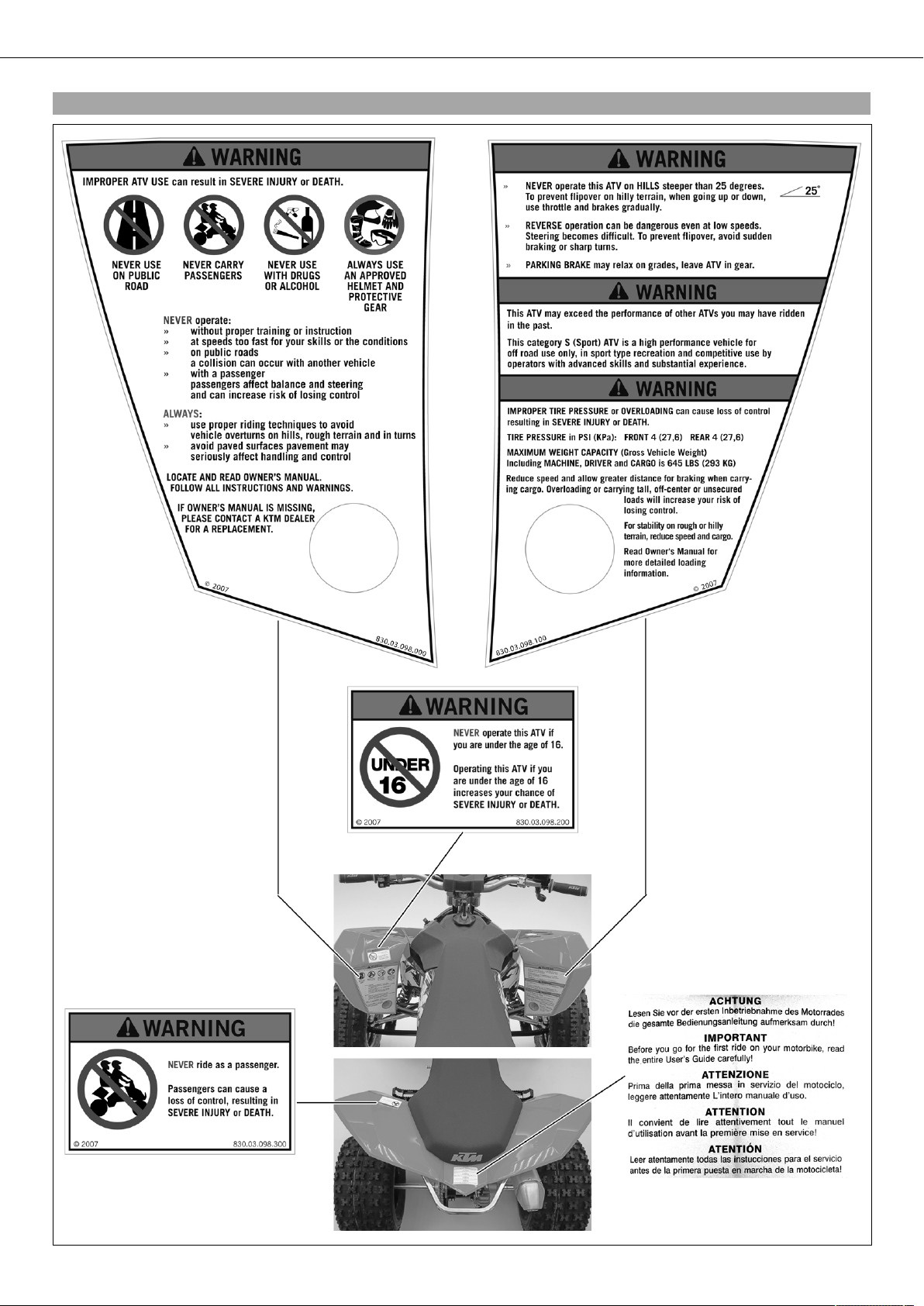
Overview of warning labels................................................ 8
VIEW OF VEHICLE............................................................. 10
Vehicle view, front left ................................................... 10
View of vehicle, rear right ............................................... 11
LOCATION OF SERIAL NUMBERS ...................................... 12
Chassis number............................................................. 12
Type label..................................................................... 12
Key number .................................................................. 12
Engine number.............................................................. 12
Setting number, front shock absorber .............................. 12
Setting number, rear shock absorber ............................... 13
VEHICLE .......................................................................... 14
Jacking up the vehicle ................................................... 14
Removing the vehicle from the work stand ....................... 14
02/HANDLEBAR, CONTROLS............................................. 15
Adjusting handlebar position .......................................... 15
Adjusting basic position of clutch lever............................ 15
Checking play in gas Bowden cable ................................. 16
Adjusting play in gas Bowden cable................................. 16
Checking the play in the Bowden cable using the reverse
gear release lever........................................................... 16
Adjusting the play in the Bowden cable using the reverse
gear release lever........................................................... 16
Detaching the reverse gear Bowden cable ........................ 17
Attaching the reverse gear Bowden cable ......................... 17
03/FRAME........................................................................ 18
Removing the engine guard ............................................ 18
Installing the engine guard ............................................. 18
04/SHOCK ABSORBER, SWINGARM................................... 19
Front shock absorber - adjusting the compression
damping ....................................................................... 19
Front shock absorber - adjusting the rebound damping...... 19
Front shock absorber - adjusting the cross over................. 20
Front shock absorber - spring preload .............................. 20
Removing the front shock absorber.................................. 21
Installing the front shock absorber .................................. 22
Front shock absorber - removing the spring ...................... 22
Front shock absorber - installing the spring...................... 23
Front shock absorber - disassembling the shock
absorber ....................................................................... 24
Front shock absorber - assembling the shock absorber ...... 25
Bleeding and filling shock absorber................................. 28
Front shock absorber - disassembling the piston rod ......... 31
Front shock absorber - assembling the piston rod.............. 32
Front shock absorber - removing the heim joint ................ 33
Front shock absorber - installing the heim joint ................ 34
Rear shock absorber - adjusting the compression
damping ....................................................................... 34
Rear shock absorber - adjusting the rebound damping....... 35
Rear shock absorber - spring preload ............................... 35
Removing the rear shock absorber................................... 36
Installing the rear shock absorber.................................... 37
Rear shock absorber - removing the spring ....................... 37
Rear shock absorber - installing the spring....................... 37
Rear shock absorber - disassembling the shock absorber ... 38
Rear shock absorber - assembling the shock absorber ....... 40
Rear shock absorber - disassembling the piston rod .......... 42
Rear shock absorber - assembling the piston rod .............. 44
Rear shock absorber - removing the heim joint ................. 46
Rear shock absorber - installing the heim joint ................. 47
05/EXHAUST .................................................................... 48
Removing the main silencer............................................ 48
Installing the main silencer ............................................ 48
Removing the manifold .................................................. 48
Installing the manifold ................................................... 49
06/AIR FILTER.................................................................. 50
Removing the air filter ................................................... 50
Installing the air filter .................................................... 50
Cleaning air filter........................................................... 50
Removing the air filter box lid with the carburetor
connection boot ............................................................ 51
Installing the air filter box lid and the carburetor
connection boot ............................................................ 51
07/FUEL TANK, SEAT, TRIM.............................................. 52
Removing the seat......................................................... 52
Mounting the seat ......................................................... 52
Removing the radiator spoiler ......................................... 52
Installing the radiator spoiler .......................................... 53
Removing the fuel tank .................................................. 53
Installing the fuel tank................................................... 54
Fuel tap........................................................................ 55
08/MASK, FENDER ........................................................... 56
Removing the front cover................................................ 56
Installing the front cover ................................................ 56
Removing the front trim ................................................. 56
Installing the front trim.................................................. 57
Removing the rear fender ............................................... 57
Installing the rear fender ................................................ 58
09/FRONT WHEEL ............................................................ 59
Checking tire air pressure............................................... 59
Tire condition checking.................................................. 59
Removing wheel/wheels.................................................. 59
Mounting wheel/wheels .................................................. 60
Checking brake discs ..................................................... 60
10/REAR WHEEL .............................................................. 61
Checking chain dirt ....................................................... 61
Cleaning the chain......................................................... 61
Checking chain wear...................................................... 61
Checking rear sprocket / engine sprocket for wear ............. 61
Checking the chain tension ............................................ 62
Adjusting chain tension.................................................. 62
Adjusting the toe width of rear axle ................................. 63
Removing the rear axle................................................... 64
Installing the rear axle ................................................... 65
Changing the rear axle bearing........................................ 67
11/WIRING HARNESS, BATTERY ....................................... 69
Ignition curve plug connection........................................ 69
Changing ignition curve.................................................. 69
Removing the battery..................................................... 69
Installing the battery...................................................... 69
Recharging the battery ................................................... 70
Changing the main fuse ................................................. 71
Changing the fuses of individual power-consuming
components .................................................................. 71
Checking the battery voltage........................................... 72
Checking the charging voltage ........................................ 72
Checking the closed-circuit current ................................. 72
Checking the starter relay............................................... 73
13/BRAKE SYSTEM........................................................... 74
Handbrake lever, parking brake....................................... 74
Checking free play of hand brake lever............................. 74
Adjusting basic position of handbrake lever...................... 74

CONTENTS 3
Checking the brake fluid level of the front brake............... 75
Adding brake fluid for the front brake .............................. 75
Checking the front brake linings...................................... 76
Removing the front brake linings..................................... 76
Mounting front brake linings........................................... 76
Changing the front brake linings ..................................... 77
Checking free play of foot brake lever .............................. 77
Adjusting basic position of footbrake lever ....................... 78
Checking the brake fluid level of the rear brake ................ 78
Adding brake fluid for the rear brake ............................... 79
Checking the rear brake linings....................................... 79
Removing the rear brake linings ...................................... 80
Mounting rear brake linings ............................................ 80
Changing the rear brake linings....................................... 81
30/ENGINE....................................................................... 82
Removing the engine ..................................................... 82
Installing the engine ...................................................... 84
30/DISASSEMBLING THE ENGINE..................................... 87
Preparations.................................................................. 87
Draining the engine oil................................................... 87
Removing the oil filter.................................................... 87
Removing the starter motor ............................................ 87
Removing the shift lever................................................. 88
Removing the clutch cover ............................................. 88
Removing the clutch discs.............................................. 88
Removing the outer clutch hub ....................................... 89
Removing the starter idler gear/torque limiter................... 90
Removing the shift shaft ................................................ 90
Removing the shift drum locating.................................... 90
Removing the locking lever............................................. 90
Removing the oil pump gear ........................................... 90
Removing the primary gear with the free-wheel-gear.......... 91
Removing the spark plug ................................................ 91
Removing the generator cover ......................................... 91
Installing the crankshaft locking bolt............................... 91
Removing the ignition pulse generator ............................. 92
Removing the rotor ........................................................ 92
Removing the oil pumps................................................. 93
Removing the oil line ..................................................... 93
Removing the timing chain tensioner............................... 94
Removing the water pump cover ..................................... 94
Removing the cylinder head top section........................... 94
Removing the camshaft.................................................. 94
Removing the cylinder head............................................ 95
Removing the cylinder ................................................... 95
Removing the piston ...................................................... 96
Removing the timing chain............................................. 96
Removing the timing chain sprocket................................ 96
Removing the locking shaft lever..................................... 96
Removing the gear sensor............................................... 97
Taking off the left section of the engine case ................... 97
Remove the shift rails and forks...................................... 98
Removing the shift drum................................................ 98
Removing the transmission shaft..................................... 99
Removing the balancer shaft .......................................... 99
Removing the crankshaft................................................ 99
30/ENGINE - WORK ON INDIVIDUAL PARTS..................... 100
Work on the right section of the engine case .................. 100
Removing the oil pressure regulator valve....................... 101
Checking the spring length of the oil pressure regulator
valve .......................................................................... 101
Installing the oil pressure regulator valve ....................... 101
Work on the left section of the engine case .................... 102
Changing the crankshaft seal ring in the clutch cover...... 102
Disassembling the autodecompressor ............................ 103
Assembling the autodecompressor................................. 104
Changing the camshaft bearing..................................... 105
Checking the rocker arms and rocker arm shafts............. 106
Removing the valves .................................................... 107
Checking the valves ..................................................... 108
Checking the valve springs ........................................... 108
Checking the lower valve spring retainer ........................ 108
Checking the cylinder head .......................................... 109
Installing the valves..................................................... 109
Checking the timing assembly ...................................... 110
Preparing the timing chain tensioner for installation ....... 110
Changing the conrod bearing ........................................ 110
Checking the crankshaft run-out on the bearing pin ........ 111
Measuring the axial clearance of the crankshaft.............. 112
Correcting the axial clearance of the crankshaft.............. 112
cylinder - Nikasil®coating ............................................ 113
Checking/measuring the cylinder................................... 113
Checking/measuring the piston ..................................... 114
Checking the piston ring end gap .................................. 114
Checking the piston/cylinder mounting clearance............ 115
Checking the oil pumps for wear ................................... 115
Checking the shift mechanism...................................... 116
Disassembling the shift shaft........................................ 117
Preassembling the shift shaft........................................ 118
Checking the clutch..................................................... 118
Disassembling the main shaft ....................................... 119
Checking the main shaft .............................................. 120
Assembling the main shaft ........................................... 121
Disassembling the countershaft .................................... 122
Checking the countershaft............................................ 123
Assembling the countershaft......................................... 124
Checking/premounting the reverse gear shaft.................. 125
Checking electric starter operation ................................ 126
Removing the free-wheel .............................................. 127
Checking the free-wheel............................................... 127
Installing the free-wheel............................................... 127
30/ASSEMBLING THE ENGINE ........................................ 128
Installing the crankshaft............................................... 128
Installing the balancer shaft ......................................... 128
Installing the transmission shaft ................................... 128
Installing the shift forks ............................................... 129
Installing the shift drum............................................... 129
Installing the shift rails ................................................ 129
Installing the left engine case....................................... 129
Installing the timing chain sprocket............................... 131
Installing the timing chain rails..................................... 131
Installing the piston..................................................... 131
Installing the cylinder .................................................. 132
Installing the cylinder head .......................................... 132
Installing the camshaft ................................................ 133
Installing the cylinder head top section.......................... 134
Installing the timing chain tensioner ............................. 135
Installing the rotor....................................................... 135
Checking the valve clearance........................................ 135
Adjusting the valve clearance........................................ 136
Installing the valve cover .............................................. 136
Installing the water pump cover .................................... 136
Installing the oil line.................................................... 136

CONTENTS 4
Installing the spark plug............................................... 136
Installing the primary gear with the free-wheel-gear ........ 137
Installing the oil pumps ............................................... 137
Installing the ignition pulse generator............................ 138
Installing the generator cover........................................ 138
Installing the gear sensor ............................................. 139
Installing the locking shaft lever ................................... 139
Installing the locking lever............................................ 139
Installing the shift drum locating .................................. 140
Installing the shift shaft ............................................... 140
Installing the starter idler gear/torque limiter.................. 140
Removing the crankshaft locking bolt ............................ 140
Installing the outer clutch hub and clutch discs ............. 141
Installing the clutch cover ............................................ 142
Installing the starter motor ........................................... 143
Installing the oil drain plug........................................... 143
Installing the oil screen................................................ 143
Mounting the oil filter .................................................. 143
Filling up with engine oil.............................................. 144
Installing the shift lever ............................................... 144
Installing the clutch push rod ....................................... 144
Removing the engine from the universal mounting
rack ........................................................................... 144
31/CARBURETOR ........................................................... 145
Choke......................................................................... 145
Hot start button........................................................... 145
Removing the carburetor .............................................. 145
Disassembling the carburetor........................................ 146
Checking/adjusting the carburetor components............... 149
Checking/adjusting the accelerator pump....................... 149
Checking the hot start slide .......................................... 150
Checking the choke slide.............................................. 150
Checking the jet needle................................................ 150
Checking the throttle slide............................................ 151
Checking the needle jet................................................ 151
Checking the float needle valve..................................... 151
Checking the throttle valve sensorTPS .......................... 152
Adjusting the position of throttle valve sensorTPS .......... 152
Checking/adjusting the throttle slide opening ................. 153
Checking/adjusting the float level.................................. 153
Assembling the carburetor............................................ 153
Installing the carburetor ............................................... 156
Carburetor - adjusting idle............................................ 157
Checking the throttle valve sensor position..................... 158
Emptying the carburetor float chamber .......................... 159
32/CLUTCH .................................................................... 160
Checking fluid level of hydraulic clutch ......................... 160
33/TRANSMISSION......................................................... 161
Removing the engine sprocket ...................................... 161
Installing the engine sprocket ....................................... 161
35/WATER PUMP, COOLING SYSTEM .............................. 162
Checking antifreeze and coolant level ............................ 162
Checking the coolant level............................................ 162
Draining coolant .......................................................... 163
Filling coolant / bleeding cooling system........................ 164
38/LUBRICATION SYSTEM .............................................. 166
Changing engine oil and oil filter, cleaning oil screens .... 166
Draining engine oil, cleaning oil screens ........................ 166
Removing the oil filter.................................................. 167
Mounting oil filter........................................................ 168
Filling up with engine oil.............................................. 168
Checking engine oil level.............................................. 169
Topping up engine oil .................................................. 169
39/IGNITION SYSTEM ..................................................... 170
Checking the generator ................................................ 170
Checking the ignition pulse generator ............................ 170
Checking the ignition coil............................................. 170
Checking the spark plug connector................................ 171
61/ATV FRONT SECTION ................................................. 172
Toe, checking ............................................................. 172
Adjusting the toe......................................................... 173
Checking/adjusting camber........................................... 174
Adjusting the fork offset............................................... 175
Removing the wheel carrier .......................................... 175
Installing the wheel carrier ........................................... 177
Removing the A-arms................................................... 178
Installing the A-arms ................................................... 178
A-Arm top - changing the bearing.................................. 179
A-Arm bottom - changing the bearing ............................ 180
TECHNICAL DATA - ENGINE............................................ 183
Capacity - engine oil .................................................... 183
Capacity - coolant........................................................ 184
TECHNICAL DATA - TOLERANCE, WEAR LIMITS OF
ENGINE ......................................................................... 185
TECHNICAL DATA - ENGINE TIGHTENING TORQUES........ 186
TECHNICAL DATA - CARBURETOR................................... 188
450/525XCATV ......................................................... 188
TECHNICAL DATA - CARBURETOR TIGHTENING
TORQUES....................................................................... 189
TECHNICAL DATA - CHASSIS .......................................... 190
Lighting equipment ..................................................... 191
Tires .......................................................................... 191
Capacity - fuel............................................................. 191
TECHNICAL DATA - FRONT SHOCK ABSORBER................ 192
TECHNICAL DATA - REAR SHOCK ABSORBER.................. 193
TECHNICAL DATA - CHASSIS TIGHTENING TORQUES ...... 194
CLEANING...................................................................... 195
Cleaning the vehicle .................................................... 195
STORAGE ....................................................................... 196
Storage....................................................................... 196
Putting the vehicle into operation after storage............... 196
GREASING AND SERVICE TABLE ..................................... 197
Important maintenance work to be carried out by an
authorized KTM workshop. ........................................... 197
Important maintenance work to be carried out by an
authorized KTM workshop. (as additional order).............. 198
Important checks and maintenance work to be carried
out by the rider. .......................................................... 198
WIRING DIAGRAM .......................................................... 200
450/525XCATV ......................................................... 200
SUBSTANCES................................................................. 203
AUXILIARY SUBSTANCES................................................ 205
SPECIAL TOOLS.............................................................. 207
STANDARDS................................................................... 216
INDEX ............................................................................ 217

MEANS OF REPRESENTATION 5
1MEANS OF REPRESENTAT ION
Symbols used
The symbols used are explained in the following.
Indicates an expected reaction (e.g. of a work step or a function).
Indicates an unexpected reaction (e.g. of a work step or a function).
Identifies a page reference (more information is provided on the specified page).
Formats used
The typographical and other formats used are explained in the following.
Name Identifies a specific name.
Registered trademark®Identifies a protected name.
Trademark™ Identifies a brand in merchandise traffic.

IMPORTANT NOTES 6
2IMPORTANT NOTES
Warranty
The maintenance work prescribed in the greasing and service table must be carried out in an authorized KTM workshop and confirmed
in the customer's service record, since otherwise no warranty claims will be recognized. No warranty claims can be considered for
damage resulting from manipulations and alterations to the vehicle.
Fuel, oils, etc.
You should use the fuels, oils and greases according to specifications as listed in the owner's manual.
Spare parts, accessories
Only use spare parts and accessory products that have been released by KTM. KTM accepts no liability for other products and any
resulting damage or loss.
Work rules
When assembling the equipment, non-reusable parts (e.g. self-locking screws and nuts, seals, seal rings, O-rings, pins, lock washers)
must be replaced with new parts.
If a thread locker (e.g.Loctite®) is used for screw connections, follow the instructions for use from the manufacturer.
Parts that are to be reused after being disassembled should be cleaned and checked for damage and wear. Replace damaged or worn
parts.
After finishing the repair and maintenance work, ensure that the vehicle is roadworthy.

IMPORTANT NOTES 7

IMPORTANT NOTES 8
2.1Overview of warning labels
100106-10

IMPORTANT NOTES 9
Notes/warning notes
Pay attention to the specified notes and warnings.
Info
Various notes and warning labels are attached to the vehicle. Do not remove any notes or warning labels. If they are missing,
you or others may not recognize dangers and may therefore be injured.
Grades of risks
Danger
Danger that leads immediately and certainly to severe and permanent injury or death.
Warning
Danger that will probably lead to severe and permanent injury or death.
Note
Danger of serious damage to machine or material.
Warning
Risk of environmental damage.
Repair manual
–Read this repair manual carefully and in its entirety before beginning work. It contains a lot of information and tips to help you
repair and maintain the vehicle.
–It is assumed that the necessary KTM special tools and workshop equipment are available to you.

VIEW OF VEHICLE 10
3VIEW OF VEHICLE
3.1Vehicle view, front left
600148-10
1 Hand brake lever
2 Fuse box
3 Headlight
4 Front shock absorber
5 Right-hand brake caliper
6 Steering damper holder (steering damper is optional)
7 Front left shock absorber
8 Outside brake disk guard
9 Shift lever
10 Left footrest
11 Heel protector
12 Emergency OFF switch with rip cord
13 Clutch lever

VIEW OF VEHICLE 11
3.2View of vehicle, rear right
600149-10
1 Light switch, electric starter button, ENG.STOPswitch
2 Filler cap
3 Main silencer
4 Rear shock absorber
5 Rear sprocket with chain
6 Rear wheel eccentric element
7 Rear brake
8 Foot brake pedal
9 Compensating tank for coolant
10 Manifold
11 Top A-arm
12 Front right fender
13 Throttle lever
14 Ignition switch

LOCATION OF SERIAL NUMBERS 12
4LOCATION OF SERIAL NU MBERS
4.1Chassis number
100002-10
The chassis numberis stamped on the right side of the frame in the vicinity of the
upper control arm.
4.2Type label
100034-10
The type labelis located on the frame tube on the right in front of the radiator.
4.3Key number
100089-10
The key numberis indicated on theKEYCODECARD.
Info
You need the key number to order a replacement key. Keep theKEYCODECARD in
a safe place.
4.4Engine number
100001-10
The engine numberis stamped on the left side of the engine under the engine
sprocket.
4.5Setting number, front shock absorber
100033-10
The setting numberis stamped into the top of the shock absorber.

LOCATION OF SERIAL NUMBERS 13
4.6Setting number, rear shock absorber
100032-10
The setting numberis stamped into the top of the shock absorber.

VEHICLE 14
5VEHICLE
5.1Jacking up the vehicle
100054-10
Note
Danger of damage Danger of damage from tipping of vehicle.
–Jack up the vehicle on a firm and horizontal surface. Use a flex-free work stand.
–Jack up the vehicle on the frame underneath the engine. The wheels must no
longer touch the ground.
–Secure the vehicle.
5.2Removing the vehicle from the work stand
Note
Danger of damage Danger of damage by the vehicle running away or falling over.
–Always place the vehicle on a firm and even surface.
–Lower the vehicle.
–Remove the work stand.

02/HANDLEBAR, CONTROLS 15
602/HANDLEBAR, CONT ROLS
6.1Adjusting handlebar position
100100-10
–Pull the instrument support off the handlebar and swing it to the side.
Info
Protect the vehicle and its attachments from damage by covering them.
Do not bend the cables and lines.
100099-10
–Remove the four screws. Remove the handlebar clamps, swing the handlebar
forward and set it down.
–Remove the nutsand remove the handlebar supportwith the screws.
–Remove screwsand.
–Remove screws. Remove the handlebar bridge.
–Check parts for damage and wear. Replace damaged or worn parts.
–Place the handlebar bridgeonto the steering column in the desired position.
Mount and tighten screw.
Specification
Screw, steering bridge M8 20Nm
(14.8lbfft)
–Mount and tighten screw.
Specification
Screw, steering column, top M20x1,5 25Nm
(18.4lbfft)
–Mount and tighten screws.
Specification
Screw, steering bridge M8 20Nm
(14.8lbfft)
–Mount the handlebar supportin the desired position using the screws. Mount
new self-locking nutsand tighten.
Specification
Nut, handlebar support M10 45Nm
(33.2lbfft)
–Position the handlebar and fix it with the handlebar clamps. Mount and tighten
screws.
Specification
Screw, handlebar clamp M8 20Nm
(14.8lbfft)
Info
Make sure cables and wiring are positioned correctly.
–Position the instrument support on the handlebar.
6.2Adjusting basic position of clutch lever
100039-10
–Adjust the basic setting of the clutch lever to your hand size by turning adjusting
screw.
Info
Turn the adjusting screw clockwise to increase the distance between the
clutch lever and the handlebar.
Turn the adjusting screw counterclockwise to decrease the distance between
the clutch lever and the handlebar.
The range of adjustment is limited.
Turn the adjusting screw by hand only, and do not apply any force.
Do not make any adjustments while riding!

02/HANDLEBAR, CONTROLS 16
6.3Checking play in gas Bowden cable
600142-10
–Move the handlebar to the straight-ahead position. Move the throttle lever back and
forth slightly to ascertain the play in the gas Bowden cable.
Specification
Play in gas Bowden cable 3… 5mm (0.12… 0.2in)
» If the gas Bowden cable play does not meet specifications:
–Adjust the play in the gas Bowden cable. ( P. 16)
Danger
Danger of poisoning Exhaust gases are poisonous and can result in uncon-
sciousness and/or death.
–When running the engine, always make sure there is sufficient ventila-
tion, and do not start or run the engine in a closed space.
–Start the engine and let it run idle. Move the handlebar to and fro over the entire
steering range.
The idle speed must not change.
» If the idle speed changes:
–Adjust the play in the gas Bowden cable. ( P. 16)
6.4Adjusting play in gas Bowden cable
–Check gas Bowden cable route.
600142-11
–Move the handlebar to the straight-ahead position.
–Loosen the nutand use the screwto adjust the play in the gas Bowden
cable.
Specification
Play in gas Bowden cable 3… 5mm (0.12… 0.2in)
–Tighten nut.
6.5Checking the play in the Bowden cable using the reverse gear release lever
600141-10
–Move the handlebar to the straight-ahead position. Move the reverse gear release
lever back and forth slightly to ascertain the play in the Bowden cable.
Specification
Play in the Bowden cable on the
reverse gear release lever
10mm (0.39in)
» If the Bowden cable play on the reverse gear release lever does not agree with
the specifications:
–Adjust the play in the Bowden cable using the reverse gear release lever.
( P. 16)
6.6Adjusting the play in the Bowden cable using the reverse gear release lever
–Check that the Bowden cable is correctly laid from the reverse gear release lever.
600141-11
–Move the handlebar to the straight-ahead position.
–Release the nutand using the screw, adjust the play of the Bowden cable
on the reverse gear release lever.
Specification
Play in the Bowden cable on the
reverse gear release lever
10mm (0.39in)
–Tighten nut.

02/HANDLEBAR, CONTROLS 17
6.7Detaching the reverse gear Bowden cable
600181-10
–Loosen nut.
–Detach the Bowden cable from abutment plateand locking shaft lever.
6.8Attaching the reverse gear Bowden cable
600181-11
–Attach the Bowden cable to locking shaft leverand abutment plate.
–Mount nutin such a way that the specified play is present in the Bowden cable.
Specification
Play in the Bowden cable on the
reverse gear release lever
10mm (0.39in)
–Tighten nut.
–Check the play in the Bowden cable using the reverse gear release lever. ( P. 16)

03/FRAME 18
703/FRAME
7.1Removing the engine guard
600133-10
–Remove screwsand. Remove the engine guard.
7.2Installing the engine guard
600133-10
–Check parts for damage and wear. Replace damaged or worn parts.
–Position the engine guard on the frame bearer. Mount and tighten screws
and.
Specification
Remaining screws, chassis M6 10Nm (7.4lbfft)
Remaining screws, chassis M8 25Nm
(18.4lbfft)
This manual suits for next models
1
Table of contents
Other KTM Offroad Vehicle manuals

KTM
KTM 545 XC ATV EU 2011 User manual

KTM
KTM 450 SX ATV 2010 Operating instructions

KTM
KTM 525 XC User manual

KTM
KTM 525 XC ATV 2008 User manual

KTM
KTM 525 XC ATV EU Manual

KTM
KTM 450 XC User manual

KTM
KTM 450 SX 2009 User manual

KTM
KTM 450 SX ATV User manual

KTM
KTM 525 XC ATV EU User manual

KTM
KTM 450 XC ATV 2009 Manual
Popular Offroad Vehicle manuals by other brands

Polaris
Polaris SPORTSMAN FOREST 800 Series owner's manual

Polaris
Polaris Magnum 330 owner's manual

Hammerhead
Hammerhead Dune Buggy GT250 owner's manual

Polaris
Polaris Trail Boss 330 Quadricycle Specification sheet

Arctic Cat
Arctic Cat 2258-642R Operation, installation, maintenance and parts manual

Yamaha
Yamaha SXV70ERJ owner's manual