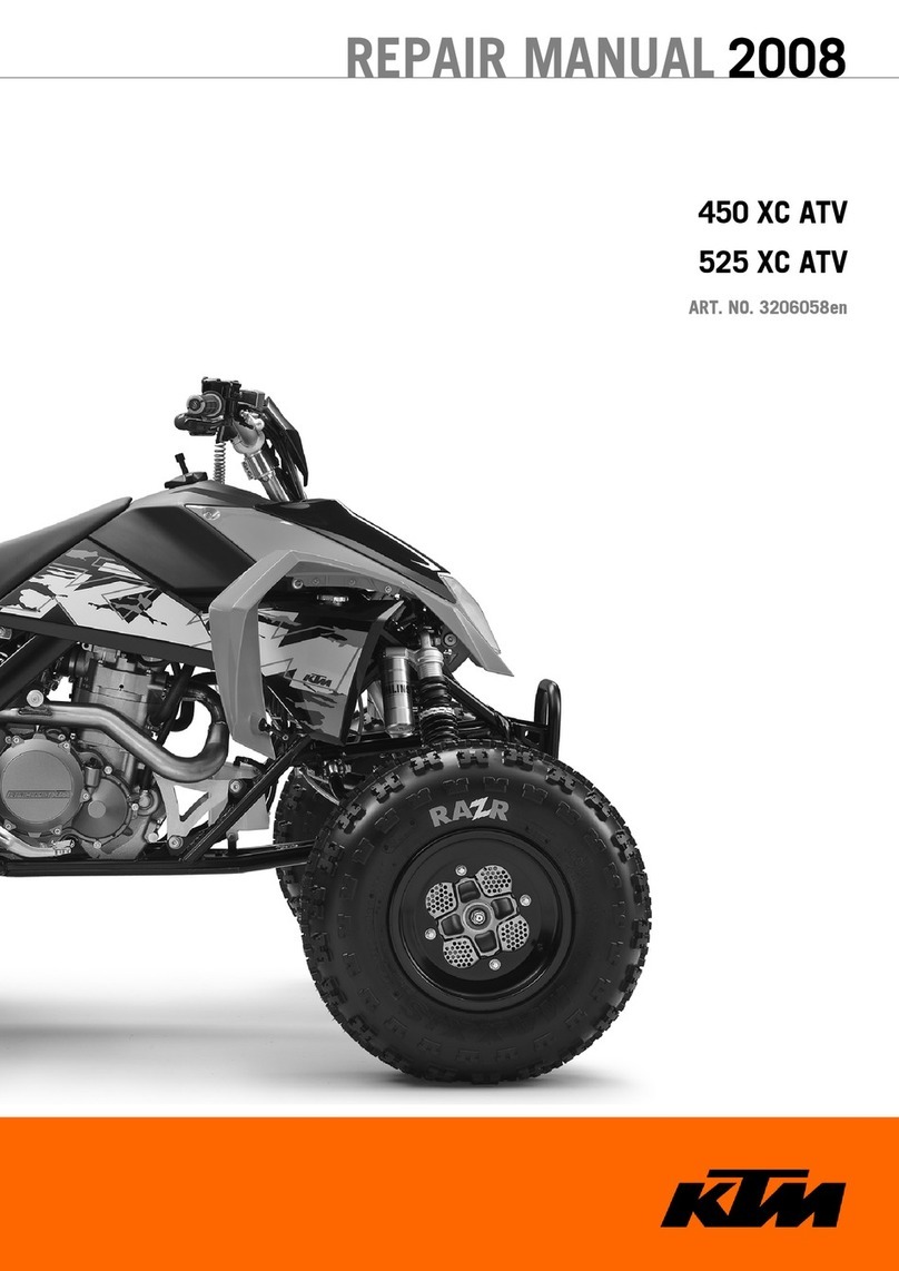
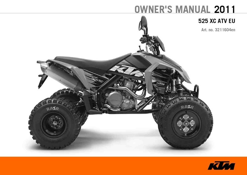
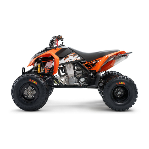
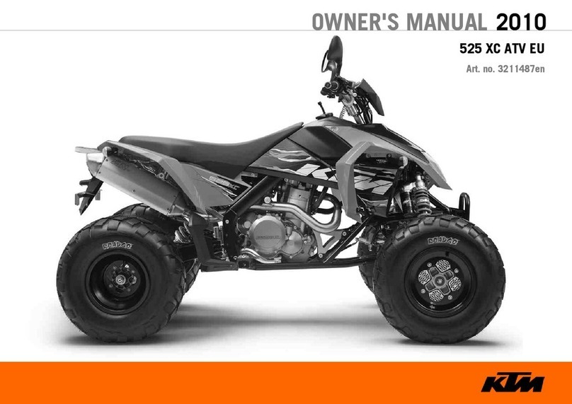
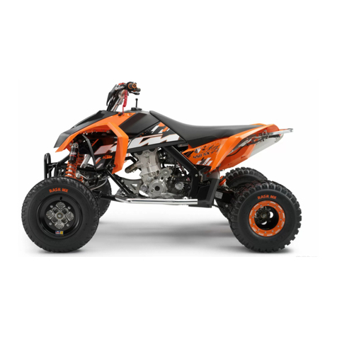
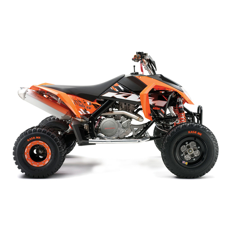
KTM 450 XC ATV 2008 Manual

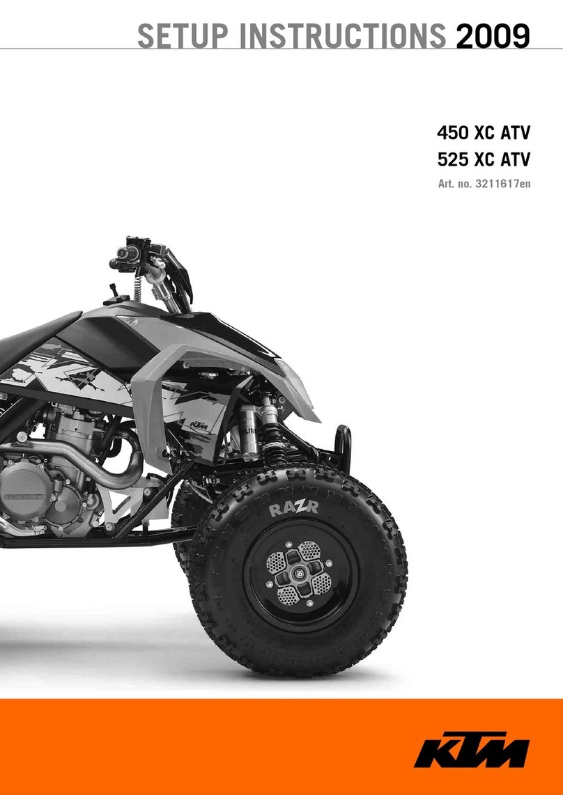
SETUP INSTRUCTIONS 2008
Package for ATV
450 XC ATV
525 XC ATV
ART. NO. 3211187en


INTRODUCTION 1
INTRODUCTION
The work described in the setup instructions must be performed before delivery to the customer.
Read the setup instructions before starting work.
Print the current PDI form from KTMDEALER.NET.
These setup instructions corresponded to the latest state of this series at the time of printing. However; we reserve the right to make
changes resulting from continuing development and design without correcting these setup instructions.
No description of general workshop procedures is provided. Safety regulations common in everyday workshop procedures are also not
mentioned. It is assumed that the work will be undertaken by a fully trained mechanic.
All specifications are not binding. KTM Sportmotorcycle AG in particular reserves the right to modify or delete technical specifica-
tions, prices, colors, forms, materials, services, designs, equipment, etc., without prior notice and without specifying reasons, to adapt
these to local conditions, as well as to stop production of a particular model without prior notice. KTM accepts no liability for delivery
options, deviations from illustrations and descriptions, as well as printing and other errors. The models portrayed partly contain special
equipment that does not belong to the regular scope of delivery.
© 2007 by KTM-Sportmotorcycle AG, Mattighofen Austria
All rights reserved
Reproduction, even in part, is permitted only with the express written permission of the copyright owner.
ISO 9001(12 100 6061)
Within the meaning of the international quality management standard ISO 9001, KTM uses quality assurance processes
that lead to the maximum possible quality of the products.
Issued by: TÜV Management Service
KTM-Sportmotorcycle AG
5230 Mattighofen, Austria

MEANS OF REPRESENTATION 2
1MEANS OF REPRESENTATION
Symbols used
The symbols used are explained in the following.
Indicates an expected reaction (e.g. of a work step or a function).
Indicates an unexpected reaction (e.g. of a work step or a function).
Identifies a page reference (more information is provided on the specified page).
Formats used
The typographical and other formats used are explained in the following.
Eigenname Identifies a specific name.
Name®Identifies a protected name.
Marke™ Identifies a brand in merchandise traffic.

SET‑UP 3
2SET‑UP
2.1
Unpacking and assembling the vehicle
200151-10
–Remove box and foils.
–Check the vehicle for transport damage.
–Take the vehicle off the palette.
–Unpack the by-pack kit and with the help of the list of contents, check that the
delivery is complete.
–Remove the rear fender. ( P. 4)
Warning
Risk of injury Battery acid and battery gases cause serious cauterization.
–Keep batteries out of the reach of children.
–Wear suitable protective clothing and goggles.
–Avoid contact with battery acid and battery gases.
–Keep the battery away from sparks or open fire. Charge only in well ven-
tilated rooms.
–In the event of skin contact, rinse with large amounts of water. If battery
acid gets in the eyes, rinse with water for at least 15 minutes and con-
tact a doctor.
–Fill the battery.
Info
Read the notes in the battery by-pack kit.
–Recharge the battery. ( P. 5)
–Install the battery. ( P. 6)
–Print out the current PDI form from KTMDEALER.NET and carry out the post-delivery
inspection.
100107-10
–Insert the ignition key1in the key cover cap2.
Info
The key cover cap is in the tool set supplied.
Read the mounting instructions on the inside of the key cover cap.

TASKS 4
3TASKS
3.1
Removing the seat
100041-10
–Pull the release hook1back. Lift up the seat at the rear, pull it back and then
remove from above.
3.2Mounting the seat
100046-10
–Check parts for damage and wear. Replace damaged or worn parts.
–Hook the slot1on the seat into the collar sleeveAof the fuel tank, lower the rear
of the seat and slide the tab2under the fuel tankB.
100043-10
–Push down the rear of the seat until the release hook3engages.
–Make sure that the seat is correctly locked in.
3.3Removing the rear fender
–Remove the seat ( P. 4)
200149-10
–Remove screws1. Remove the collar sleeves.

TASKS 5
200148-10
–Raise the rear of the air filter box lid2. At the same time, use your other hand to
press on the carburetor connection boot to kink it at that location. This prevents the
carburetor connection boot from disconnecting from the carburetor.
–Raise the fender3at the rear and remove it.
3.4Installing the rear fender
200148-11
–Check parts for damage and wear. Replace damaged or worn parts.
–Raise the rear of the air filter box lid1. At the same time, use your other hand to
press on the carburetor connection boot to kink it at that location. This prevents the
carburetor connection boot from disconnecting from the carburetor.
–Position the front fender2.
–Fix the air filter box lid in the fender.
200149-11
–Fit and tighten screws3with collar sleeves.
Specification
Remaining screws, chassis M6 10Nm (7.4lbfft)
–Mount the seat ( P. 4)
3.5Recharging the battery
Warning
Risk of injury Battery acid and battery gases cause serious cauterization.
–Keep batteries out of the reach of children.
–Wear suitable protective clothing and goggles.
–Avoid contact with battery acid and battery gases.
–Keep the battery away from sparks or open fire. Charge only in well ventilated rooms.
–In the event of skin contact, rinse with large amounts of water. If battery acid gets in the eyes, rinse with water for at least
15 minutes and contact a doctor.
Warning
Environmental hazard Components and battery acid are a danger to the environment.
–Do not dispose of batteries in normal household waste. Take defective or used batteries to a battery recycling operator.
Warning
Environmental hazard Problem materials cause environmental damage.
–Dispose of oil, grease, filters, fuel, cleaning substances, brake fluid, batteries, etc. according to regulations.

TASKS 6
Info
Even if there is no load on the battery, it loses power every day.
The charge state and the type of charge are very important for the service life of the battery.
Fast recharging with a high charge current shortens the battery's service life.
If the charge current, the charge voltage and the charge time are exceeded, electrolyte escapes through the breathing holes.
The battery capacity is then reduced.
If the battery is discharged from starting, it must be recharged immediately.
If it stands for a long time in a discharged state, the battery becomes over-discharged and sulfated, and then it is destroyed.
The battery is maintenance-free, i.e., the acid level does not have to be checked.
–Switch off all power-consuming components and switch off the engine.
–Remove the rear fender. ( P. 4)
–Disconnect the minus (negative) cable of the battery to avoid damage to the vehi-
cle's electronics.
100087-10
–Connect the battery charger to the battery. Switch on the battery charger.
Battery charger(58429074000)
You can also use the battery charger to test rest potential and start potential of the
battery, and to test the generator. With this device, you cannot overcharge the bat-
tery.
Info
Never remove the lid1.
Charge the battery according to the instructions2on the battery casing.
–Switch off the charger after charging. Disconnect the battery.
Specification
The charge current, charge voltage and charge time must not be exceeded.
Charge the battery regularly when the
vehicle is not in use.
3months
–Install the rear fender. ( P. 5)
3.6Installing the battery
200150-11
–Check parts for damage and wear. Replace damaged or worn parts.
–Place the battery in the battery holder.
4Ah battery(YTX5L-BS)
–Reconnect the rubber band1.
–Attach the plus cable and replace the plus pole cover2.
–Connect the negative (minus) cable3of the battery.
–Install the rear fender. ( P. 5)

TECHNICAL DATA - CHASSIS TIGHTENING TORQUES 7
4TECHNICAL DATA - CHASSIS TIGHTENING TORQUES
Remaining nuts, chassis M6 15Nm (11.1lbfft) –
Remaining screws, chassis M6 10Nm (7.4lbfft) –
Screw on fuel tank M6 6Nm (4.4lbfft) –
Screw, rear brake caliper M6 10Nm (7.4lbfft) Loctite®243™
Screw, foot brake cylinder M6 7Nm (5.2lbfft) Loctite®243™
Screw, clamping nut, rear axle M6 10Nm (7.4lbfft) –
Remaining nuts, chassis M8 30Nm (22.1lbfft) –
Remaining screws, chassis M8 25Nm (18.4lbfft) –
Screw, front brake disc M8 25Nm (18.4lbfft) Loctite®243™
Screw, rear brake disc M8 25Nm (18.4lbfft) Loctite®243™
Screw, front brake caliper M8 20Nm (14.8lbfft) Loctite®243™
Screw, rear brake caliper M8 20Nm (14.8lbfft) Loctite®243™
Screw, bearing support, steering M8 25Nm (18.4lbfft) –
Screw, steering bridge M8 20Nm (14.8lbfft) –
Screw, handlebar clamp M8 20Nm (14.8lbfft) –
Screw, subframe M8 35Nm (25.8lbfft) Loctite®243™
Screw, rear wheel eccentric element M8 20Nm (14.8lbfft) –
Nut, ball head, A-arm top M10x1,25 35Nm (25.8lbfft) –
Nut, rear sprocket screw M10x1,25 45Nm (33.2lbfft) Loctite®243™
Nut, tie rod end M10x1,25 45Nm (33.2lbfft) –
Wheel nut M10x1,25 45Nm (33.2lbfft) –
Nut, handlebar support M10 45Nm (33.2lbfft) –
Remaining nuts, chassis M10 50Nm (36.9lbfft) –
Remaining screws, chassis M10 45Nm (33.2lbfft) –
Engine carrying screw M10 60Nm (44.3lbfft) –
Screw, A-arm top M10x52 45Nm (33.2lbfft) –
Screw, A-arm bottom M10x70 45Nm (33.2lbfft) –
Screw, front shock absorber M10 45Nm (33.2lbfft) –
Screw, footrest M10 45Nm (33.2lbfft) –
Screw, steering column at bottom of
steering lever
M10 25Nm (18.4lbfft) –
Engine bracket screw M10 60Nm (44.3lbfft) –
Nut, A-arm top M12x1,25 30Nm (22.1lbfft) –
Lock nut, tie rod, outside M12x1,25 20Nm (14.8lbfft) –
Lock nut, tie rod, inside M12LHx1,25 20Nm (14.8lbfft) –
Nut, ball head, A-arm bottom M12x1,5 40Nm (29.5lbfft) –
Nut, front wheel hub M12 70Nm (51.6lbfft) –
Screw, rear top shock absorber M12 60Nm (44.3lbfft) –
Screw, rear bottom shock absorber M12 70Nm (51.6lbfft) –
Nut, swingarm pivot M16x1,5 100Nm (73.8lbfft) –
Nut, rear wheel hub M18x1,5 130Nm (95.9lbfft) –
Screw, steering column, top M20x1,5 25Nm (18.4lbfft) –
Screw, steering column, bottom M20x1,5 40Nm (29.5lbfft) –
Clamping nut, rear axle 2"-10UNS-2B-LH 25Nm (18.4lbfft) Only applies when using:
Open-end wrench accessory
46mm (83019010461)

*3211187en*
3211187en
KTM-Sportmotorcycle AG
5230 Mattighofen/Austria
http://www.ktm.com
7/2007
Photo Mitterbauer
This manual suits for next models
1
Table of contents
Other KTM Offroad Vehicle manuals

KTM
KTM 525 XC ATV EU User manual

KTM
KTM 2008 450 XC ATV Operating instructions

KTM
KTM 450 XC User manual

KTM
KTM 545 XC ATV EU 2011 User manual

KTM
KTM 450 SX ATV 2009 Manual

KTM
KTM 525 XC ATV 2008 User manual

KTM
KTM 450 XC ATV 2009 Manual

KTM
KTM 450 SX 2009 User manual

KTM
KTM 525 XC User manual

KTM
KTM 505 SX ATV User manual