KTM 450 SX ATV 2010 Operating instructions

REPAIR MANUAL 2010
450 SX ATV
505 SX ATV
Article no. 3206070en
PartShark.com
877-999-5686

PartShark.com
877-999-5686

INTRODUCTION 1
INTRODUCTION
It is important that you read this owner's manual carefully and completely before the start of work.
Only use ORIGINAL KTM SPARE PARTS.
This vehicle can only fulfill the demands placed on it in the long run if the specified service work is performed regularly by qualified
experts.
The repair manual was written to correspond to the most current state of this model series. We reserve the right to make changes in
the interest of technical advancement without, at the same time, updating this repair manual.
We shall not provide a description of general workshop methods. Likewise, safety rules that apply in a workshop are not specified here.
It is assumed that repair work will be performed by a fully trained mechanic.
All specifications are non-binding. KTM Sportmotorcycle AG specifically reserves the right to modify or delete technical specifica-
tions, prices, colors, forms, materials, services, designs, equipment, etc., without prior notice and without specifying reasons, to adapt
these to local conditions, as well as to stop production of a particular model without prior notice. KTM accepts no liability for delivery
options, deviations from illustrations and descriptions, as well as misprints and other errors. The models portrayed partly contain spe-
cial equipment that does not belong to the regular scope of delivery.
© 2009 by KTM-Sportmotorcycle AG, Mattighofen Austria
All rights reserved
Reproduction, even in part, is permitted only with the express written permission of the copyright owner.
ISO 9001(12 100 6061)
According to the international quality management standard ISO 9001, KTM uses quality assurance processes that lead
to the maximum possible quality of the products.
Issued by: TÜV Management Service
KTM-Sportmotorcycle AG
5230 Mattighofen, Austria
PartShark.com
877-999-5686

CONTENTS 2
CONTENTS
MEANS OF REPRESENTATION ............................................ 6
IMPORTANT NOTES............................................................ 7
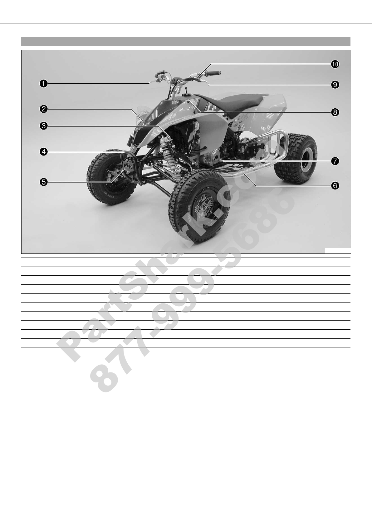
VIEW OF VEHICLE............................................................... 8
View of the vehicle from the left front (example)................. 8
View of the vehicle from the right rear (example) ................ 9
LOCATION OF SERIAL NUMBERS ...................................... 10
Chassis number............................................................. 10
Type label..................................................................... 10
Key number .................................................................. 10
Engine number.............................................................. 10
Shock absorber part number, front .................................. 10
Shock absorber part number, rear ................................... 11
VEHICLE .......................................................................... 12
Jacking up the vehicle ................................................... 12
Removing the vehicle from the work stand ....................... 12
02/HANDLEBAR, INSTRUMENTS....................................... 13
Hot start lever ............................................................... 13
Adjusting handlebar position .......................................... 13
Adjusting basic position of clutch lever............................ 14
Checking the play in the throttle cable............................. 14
Adjusting play in throttle cable ....................................... 14
Removing the steering column........................................ 14
Changing the steering column bearing ............................. 16
Installing the steering column......................................... 18
03/FRAME........................................................................ 20
Removing the engine guard ............................................ 20
Installing the engine guard ............................................. 20
04/SHOCK ABSORBER, SWINGARM................................... 21
Front shock absorber - adjusting the high-speed
compression damping .................................................... 21
Front shock absorber - adjusting the low-speed
compression damping .................................................... 21
Front shock absorber - adjusting the rebound damping...... 22
Front shock absorber - adjusting the spring preload .......... 23
Front shock absorber - adjusting the cross over................. 24
Removing the front shock absorber.................................. 24
Installing the front shock absorber .................................. 25
Front shock absorber - changing the oil ........................... 25
Service the front shock absorber ..................................... 27
Front shock absorber - removing the spring ...................... 28
Front shock absorber - disassembling the damper............. 28
Front shock absorber - disassembling the piston rod ......... 29
Front shock absorber - checking the damper .................... 30
Front shock absorber - removing the heim joint ................ 31
Front shock absorber - installing the heim joint ................ 31
Front shock absorber - assembling the piston rod.............. 32
Front shock absorber - assembling the damper ................. 33
Front shock absorber - bleeding and filling the damper ..... 34
Front shock absorber - filling the damper with nitrogen ..... 37
Front shock absorber - installing the spring...................... 38
Rear shock absorber - adjusting the high-speed
compression damping .................................................... 38
Rear shock absorber - adjusting the low-speed
compression damping .................................................... 39
Rear shock absorber - adjusting the rebound damping....... 40
Rear shock absorber - adjusting the spring preload ........... 40
Removing the rear shock absorber................................... 41
Installing the rear shock absorber.................................... 42
Rear shock absorber - changing the oil ............................ 42
Servicing the rear shock absorber.................................... 44
Rear shock absorber - removing the spring ....................... 44
Rear shock absorber - disassembling the damper.............. 45
Rear shock absorber - disassembling the piston rod .......... 46
Rear shock absorber - disassembling the seal ring
retainer ........................................................................ 47
Changing the pilot bushing............................................. 47
Rear shock absorber - checking the damper ..................... 48
Rear shock absorber - removing the heim joint ................. 49
Rear shock absorber - installing the heim joint ................. 50
Rear shock absorber - assembling the seal ring retainer..... 50
Rear shock absorber - assembling the piston rod .............. 51
Rear shock absorber - assembling the damper.................. 52
Rear shock absorber - bleeding and filling the damper ...... 54
Rear shock absorber - filling the damper with nitrogen ...... 56
Rear shock absorber - installing the spring....................... 57
05/EXHAUST .................................................................... 59
Removing the main silencer............................................ 59
Installing the main silencer ............................................ 59
Removing the manifold .................................................. 60
Installing the manifold ................................................... 60
06/AIR FILTER.................................................................. 61
Removing the air filter ................................................... 61
Installing the air filter .................................................... 61
Cleaning air filter........................................................... 61
Removing the air filter box lid with the carburetor
connection boot ............................................................ 62
Installing the air filter box lid and the carburetor
connection boot ............................................................ 62
07/FUEL TANK, SEAT, TRIM.............................................. 63
Removing the seat......................................................... 63
Mounting the seat ......................................................... 63
Removing the radiator spoiler ......................................... 63
Installing the radiator spoiler .......................................... 64
Removing the fuel tank .................................................. 64
Installing the fuel tank................................................... 65
Fuel tap........................................................................ 66
08/MASK, FENDER ........................................................... 67
Removing the heel protector ........................................... 67
Installing the heel protector............................................ 68
Removing the front cover................................................ 69
Installing the front cover ................................................ 69
Removing the front trim ................................................. 69
Installing the front trim.................................................. 70
Removing the rear fender ............................................... 70
Installing the rear fender ................................................ 71
09/FRONT WHEEL ............................................................ 72
Checking the tire air pressure ......................................... 72
Checking the tire condition............................................. 72
Removing wheel/wheels.................................................. 72
Installing the wheel/wheels............................................. 73
Checking brake discs ..................................................... 74
10/REAR WHEEL .............................................................. 75
Checking chain dirt ....................................................... 75
Cleaning the chain......................................................... 75
Checking chain wear...................................................... 75
Checking rear sprocket / engine sprocket for wear ............. 76
Checking the chain tension ............................................ 76
Adjusting chain tension.................................................. 76
Adjusting the toe width of rear axle ................................. 77
Removing the rear axle................................................... 78
Installing the rear axle ................................................... 79
Changing the rear axle bearing........................................ 81
11/WIRING HARNESS, BATTERY ....................................... 83
Ignition curve plug connection........................................ 83
PartShark.com
877-999-5686

CONTENTS 3
Changing the ignition curve ............................................ 83
Removing the battery..................................................... 83
Installing the battery...................................................... 83
Recharging the battery ................................................... 84
Changing the main fuse ................................................. 85
Changing the fuses of individual power consumers............ 85
Checking the battery voltage........................................... 86
Checking the charging voltage ........................................ 86
Checking the quiescent current....................................... 86
Checking the starter relay............................................... 87
13/BRAKE SYSTEM........................................................... 88
Hand brake lever, parking brake...................................... 88
Checking the free travel of the hand brake lever ............... 88
Adjusting basic position of hand brake lever..................... 88
Checking front brake fluid level....................................... 89
Topping up the front brake fluid...................................... 89
Changing the front brake fluid ........................................ 90
Checking the front brake linings...................................... 91
Removing front brake linings .......................................... 91
Mounting front brake linings........................................... 92
Changing the front brake linings ..................................... 92
Checking free travel of foot brake lever ............................ 93
Adjusting basic position of foot brake lever ...................... 93
Checking rear brake fluid level........................................ 94
Adding rear brake fluid .................................................. 94
Changing the rear brake fluid.......................................... 95
Checking rear brake linings ............................................ 96
Removing rear brake linings............................................ 96
Mounting rear brake linings ............................................ 97
Changing rear brake linings ............................................ 98
30/ENGINE....................................................................... 99
Removing the engine ..................................................... 99
Installing the engine .................................................... 100
30/DISASSEMBLING THE ENGINE................................... 103
Preparations................................................................ 103
Removing the shift lever............................................... 103
Draining the engine oil................................................. 103
Removing the oil filter.................................................. 103
Removing the spark plug.............................................. 104
Removing the valve cover ............................................. 104
Removing the starter motor .......................................... 104
Removing the alternator cover....................................... 104
Removing the torque limiter ......................................... 105
Positioning the engine at ignition top dead center
(TDC) ......................................................................... 105
Removing the camshaft................................................ 106
Removing the timing chain tensioner............................. 106
Removing the double wheel.......................................... 107
Removing the cylinder head.......................................... 107
Removing the water pump cover ................................... 108
Removing the clutch cover ........................................... 108
Removing the piston .................................................... 109
Removing the timing chain rails.................................... 109
Removing the timing chain........................................... 109
Removing the rotor and starter idler gear ....................... 110
Removing the ignition pulse generator ........................... 110
Removing the drive wheel of the balancer gear ............... 111
Removing the force pump ............................................ 111
Removing the spacer ................................................... 112
Removing the outer clutch hub ..................................... 112
Removing the primary gear ........................................... 113
Removing the centrifugal separator ............................... 113
Removing the suction pump ......................................... 114
Removing the shift shaft .............................................. 114
Removing the shift drum locating unit........................... 115
Removing the locking lever........................................... 115
Removing the left section of the engine case.................. 115
Removing the shift rails ............................................... 116
Removing the shift drum.............................................. 116
Removing the shift forks .............................................. 116
Removing the transmission shafts ................................. 116
Removing the crankshaft.............................................. 117
30/ENGINE - WORK ON INDIVIDUAL PARTS..................... 118
Working on the right section of the engine case.............. 118
Working on the left section of the engine case................ 119
Removing the water pump............................................ 120
Changing the shaft seal ring of the water pump .............. 121
Installing the water pump............................................. 122
Removing the crankshaft seal ring in the clutch cover ..... 123
Installing the crankshaft seal ring in the clutch cover...... 123
Removing the oil pressure regulator valve....................... 123
Checking spring length of oil pressure regulator valve...... 123
Installing the oil pressure regulator valve ....................... 124
Checking the lubrication system.................................... 124
Removing the crankshaft bearing inner race................... 125
Installing the crankshaft bearing inner race.................... 125
Changing connecting rod, conrod bearing and crank
pin............................................................................. 125
Checking crankshaft run-out at bearing pin .................... 126
Measuring the crankshaft end play ................................ 127
Cylinder - Nikasil®coating............................................ 127
Checking/measuring cylinder ........................................ 127
Checking/measuring the piston ..................................... 128
Measuring piston/cylinder mounting clearance................ 129
Checking the piston ring end gap .................................. 129
Changing the camshaft bearing..................................... 129
Checking the autodecompressor.................................... 130
Checking camshafts..................................................... 130
Checking the radial clearance of the camshaft
bearings ..................................................................... 130
Checking the camshaft bearing bridges.......................... 131
Removing the valves .................................................... 131
Checking the valves ..................................................... 132
Checking the valve springs ........................................... 133
Checking valve spring seat............................................ 133
Checking the cam levers .............................................. 133
Checking cylinder head ................................................ 133
Installing the valves..................................................... 134
Removing the freewheel ............................................... 135
Checking the freewheel ................................................ 135
Installing the free wheel............................................... 135
Checking the electric starter mode ................................ 136
Checking the timing assembly ...................................... 137
Preparing the timing chain tensioner for installation ....... 137
Checking clutch .......................................................... 138
Checking shift mechanism ........................................... 139
Preassembling the shift shaft........................................ 140
Disassembling the main shaft ....................................... 141
Disassembling the countershaft .................................... 141
Checking transmission ................................................. 142
Assembling the main shaft ........................................... 143
Assembling the countershaft......................................... 144
30/ENGINE ASSEMBLY ................................................... 145
Installing the crankshaft............................................... 145
PartShark.com
877-999-5686

CONTENTS 4
Installing the transmission shafts.................................. 145
Installing the shift forks ............................................... 145
Installing the shift drum............................................... 146
Installing the shift rails ................................................ 146
Installing the left engine case....................................... 146
Installing the locking lever............................................ 147
Installing the shift drum locating unit............................ 147
Installing the shift shaft ............................................... 147
Installing the suction pumps ........................................ 147
Installing the centrifugal separator ................................ 148
Installing the force pump ............................................. 148
Installing the primary gear............................................ 149
Installing the outer clutch hub...................................... 149
Installing the spacer .................................................... 150
Installing the drive wheel of the balancer gear................ 151
Installing the timing chain............................................ 151
Installing the free wheel gear........................................ 151
Installing the ignition pulse generator............................ 152
Installing the rotor....................................................... 152
Installing the timing chain rails..................................... 152
Installing the piston..................................................... 152
Installing the clutch cover ............................................ 154
Installing the water pump cover .................................... 154
Installing the cylinder head .......................................... 155
Installing the double wheel........................................... 155
Installing the timing chain tensioner ............................. 156
Checking the valve timing ............................................ 156
Adjusting the valve timing ............................................ 157
Checking the valve clearance........................................ 158
Adjusting the valve clearance........................................ 158
Installing the torque limiter .......................................... 159
Installing the alternator cover ....................................... 159
Installing the starter motor ........................................... 159
Installing the valve cover .............................................. 159
Installing the spark plug............................................... 160
Installing the oil screen................................................ 160
Installing the oil filter .................................................. 160
Installing the shift lever ............................................... 161
Removing the engine from the universal mounting
rack ........................................................................... 161
31/CARBURETOR ........................................................... 162
Choke......................................................................... 162
Checking the play in the throttle cable........................... 162
Carburetor - adjusting idle............................................ 162
Checking the position of the throttle position sensor ....... 163
Draining the carburetor float chamber ........................... 164
Removing the carburetor .............................................. 164
Installing the carburetor............................................... 166
Disassembling the carburetor........................................ 167
Checking/adjusting the carburetor components............... 170
Checking/adjusting the accelerator pump....................... 170
Checking the choke slide.............................................. 171
Checking the hot start slide .......................................... 171
Checking the throttle position sensor............................. 171
Checking the jet needle................................................ 172
Checking the throttle slide............................................ 172
Checking/adjusting the throttle slide opening ................. 173
Checking the needle jet................................................ 173
Checking the float needle valve..................................... 173
Checking/adjusting the float level.................................. 174
Adjusting the position of the throttle position sensor ....... 174
Assembling the carburetor............................................ 175
32/CLUTCH .................................................................... 178
Checking fluid level of hydraulic clutch ......................... 178
Changing the hydraulic clutch fluid............................... 178
33/TRANSMISSION......................................................... 179
Removing the engine sprocket ...................................... 179
Installing the engine sprocket ....................................... 179
35/WATER PUMP, COOLING SYSTEM .............................. 180
Checking antifreeze and coolant level............................ 180
Checking the coolant level............................................ 180
Draining coolant .......................................................... 181
Filling coolant/bleeding the cooling system .................... 181
38/LUBRICATION SYSTEM .............................................. 183
Oil circuit ................................................................... 183
Changing the engine oil and oil filter, cleaning the oil
screen ........................................................................ 183
Draining the engine oil................................................. 184
Removing the oil filter.................................................. 184
Installing the oil filter .................................................. 185
Filling up with engine oil.............................................. 185
Checking the engine oil level ........................................ 185
Adding engine oil ........................................................ 186
39/IGNITION SYSTEM ..................................................... 187
Removing the stator..................................................... 187
Installing the stator ..................................................... 187
Checking the ignition system ........................................ 187
Checking the ignition coil............................................. 188
Checking the spark plug connector................................ 189
Checking the CDI controller.......................................... 189
Checking the ignition pulse generator............................ 189
Checking the alternator ................................................ 190
61/ATV FRONT END........................................................ 191
Checking the toe ......................................................... 191
Adjusting the toe......................................................... 192
Checking/adjusting the camber ..................................... 193
Adjusting the fork offset............................................... 194
Removing the wheel carrier .......................................... 194
Changing the wheel bearing.......................................... 196
Installing the wheel carrier ........................................... 197
Removing the A-arms................................................... 198
Installing the A-arms ................................................... 199
A-Arm top - changing the bearing.................................. 200
A-Arm bottom - changing the bearing ............................ 201
TECHNICAL DATA - ENGINE............................................ 204
Capacity - engine oil .................................................... 204
Capacity - coolant........................................................ 204
TECHNICAL DATA - ENGINE TOLERANCES, WEAR
LIMITS........................................................................... 205
TECHNICAL DATA - ENGINE TIGHTENING TORQUES........ 206
TECHNICAL DATA - CARBURETOR................................... 208
TECHNICAL DATA - CARBURETOR TIGHTENING
TORQUES....................................................................... 209
TECHNICAL DATA - CHASSIS .......................................... 210
Tires .......................................................................... 211
Capacity - fuel............................................................. 211
TECHNICAL DATA - FRONT SHOCK ABSORBER................ 212
TECHNICAL DATA - REAR SHOCK ABSORBER.................. 213
TECHNICAL DATA - CHASSIS TIGHTENING TORQUES ...... 214
CLEANING...................................................................... 215
Cleaning the vehicle .................................................... 215
STORAGE ....................................................................... 216
Storage....................................................................... 216
Putting the vehicle into operation after storage............... 216
PartShark.com
877-999-5686

CONTENTS 5
SERVICE SCHEDULE....................................................... 217
Important maintenance work to be carried out by an
authorized KTM workshop ............................................ 217
Important maintenance work to be carried out by an
authorized KTM workshop (as an additional order) .......... 218
Important checks and maintenance work to be carried
out by the rider ........................................................... 218
WIRING DIAGRAM .......................................................... 220
450/525 SX ATV......................................................... 220
SUBSTANCES................................................................. 223
AUXILIARY SUBSTANCES................................................ 225
SPECIAL TOOLS.............................................................. 227
STANDARDS................................................................... 240
INDEX ............................................................................ 241
PartShark.com
877-999-5686

MEANS OF REPRESENTATION 6
Symbols used
The symbols used are explained in the following.
Indicates an expected reaction (e.g. of a work step or a function).
Indicates an unexpected reaction (e.g. of a work step or a function).
Identifies a page reference (more information is provided on the specified page).
Formats used
The typographical and other formats used are explained below.
Proprietary name Denotes a proprietary name.
Name®Denotes a protected name.
Brand™ Denotes a brand available on the open market.
PartShark.com
877-999-5686

IMPORTANT NOTES 7
Warranty
The work prescribed in the service schedule must be carried out in an authorized KTM workshop only and confirmed in the customer's
service record, since otherwise no warranty claims will be recognized. No warranty claims can be accepted for damage resulting from
manipulations and/or alterations to the vehicle.
Fuel, oils, etc.
You should use the fuels, oils and greases according to specifications as listed in the owner's manual.
Spare parts, accessories
Use only spare parts and accessories approved and/or recommended by KTM. KTM accepts no liability for other products and any
resulting damage or loss.
The current KTM PowerParts for your vehicle can be found on the KTM website.
International KTM Website: http://www.ktm.com
Work rules
Special tools are needed for certain tasks. They are not included with the vehicle but can be ordered under the number in parenthe-
ses. E.g.: valve spring mounter (59029019000)
When assembling the equipment, non-reusable parts (e.g. self-locking screws and nuts, seals, seal rings, O-rings, pins, lock washers)
must be replaced with new parts.
If a thread locker (e.g. Loctite®) is used for screw connections, follow the instructions for use from the manufacturer.
Parts that are to be reused after being disassembled should be cleaned and checked for damage and wear. Replace damaged or worn
parts.
After finishing the repair and maintenance work, ensure that the vehicle is roadworthy.
Notes/warnings
Pay close attention to the notes/warnings.
Info
Various information and warning labels are affixed to the vehicle. Do not remove information/warning labels. If they are miss-
ing, you or others may not recognize potential hazards and may therefore be injured.
Grades of risks
Danger
Identifies a danger that will immediately and invariably lead to fatal or serious permanent injury if the appropriate measures
are not taken.
Warning
Identifies a danger that is likely to lead to fatal or serious injury if the appropriate measures are not taken.
Note
Identifies a danger that will lead to considerable machine and material damage if the appropriate measures are not taken.
Warning
Identifies a danger that will lead to environmental damage if the appropriate measures are not taken.
Repair instructions
–It is imperative that you read this owner's manual carefully and completely before the start of work. It contains extensive informa-
tion and many tips to help you repair and maintain your vehicle.
–The necessary KTM special tools must be available and the workplace and workshop must be fully equipped.
PartShark.com
877-999-5686

VIEW OF VEHICLE 8
3.1View of the vehicle from the left front (example)
301769-10
1 Hand brake lever
2 Fuse box
3 Shock absorber compression adjustment
4 Front shock absorber
5 Shock absorber rebound adjustment
6 Heel protector
7 Shift lever
8 Kill switch/emergency OFF switch with rip cord
9 Clutch lever
10 Hot start lever
PartShark.com
877-999-5686

VIEW OF VEHICLE 9
3.2View of the vehicle from the right rear (example)
301770-10
1 Filler cap
2 Main silencer
3 Seat release
4 Shock absorber rebound adjustment
5 Rear sprocket with chain
6 Rear wheel eccentric element
7 Rear brake
8 Foot brake pedal
9 Handlebar bridge
10 Throttle lever
11 Handlebar cushion
PartShark.com
877-999-5686

LOCATION OF SERIAL NUMBERS 10
4.1Chassis number
301771-10
The chassis number is stamped on the right side of the frame in the vicinity of the
upper control arm.
4.2Type label
301858-10
The type label is located on the frame tube on the right and left in front of the radia-
tor.
4.3Key number
100089-10
The key number is indicated on the KEYCODECARD.
Info
You need the key number to order a replacement key. Keep the KEYCODECARD in
a safe place.
4.4Engine number
301772-10
The engine number is stamped on the left side of the engine under the engine
sprocket.
4.5Shock absorber part number, front
301832-10
The shock absorber part number is stamped on the upper part of the shock
absorber.
PartShark.com
877-999-5686

LOCATION OF SERIAL NUMBERS 11
4.6Shock absorber part number, rear
301831-10
The shock absorber part number is stamped on the upper part of the shock
absorber.
PartShark.com
877-999-5686

VEHICLE 12
5.1Jacking up the vehicle
301785-10
Note
Danger of damage Danger of damage from tipping of vehicle.
–Jack up the vehicle on a firm and horizontal surface. Use a flex-free work stand.
–Jack up the vehicle on the frame underneath the engine. The wheels must no
longer touch the ground.
–Secure the vehicle.
5.2Removing the vehicle from the work stand
Note
Danger of damage The parked vehicle may roll away or fall over.
–Always place the vehicle on a firm and even surface.
–Lower the vehicle.
–Remove the work stand.
PartShark.com
877-999-5686

02/HANDLEBAR, INSTRUMENTS 13
6.1Hot start lever
301775-10
Hot start lever is fitted on the left side of the handlebar.
If you pull the hot start lever to the handlebar when starting the engine, an opening is
exposed in the carburetor through which the engine can draw additional air. This gives
a leaner fuel-air mixture, which is needed for a hot start.
Possible states
• Hot start function is activated –The hot start lever has been pulled all the way
out.
• Hot start function is deactivated –The hot start lever has been pushed all the way
in.
6.2Adjusting handlebar position
301846-10
–Remove the handlebar cushion.
Info
Protect the vehicle and its attachments from damage by covering them.
Do not bend the cables and lines.
100099-10
–Remove the four screws . Remove the handlebar clamps , swing the handlebar
forward and set it down.
–Remove the nuts and remove the handlebar support with the screws.
–Remove screws and .
–Remove screws . Remove the handlebar bridge .
–Place the handlebar bridge onto the steering column in the desired position.
Mount and tighten screw .
Guideline
Screw, steering bridge M8 20 Nm
(14.8 lbf ft)
–Mount and tighten screw .
Guideline
Screw, steering column, top M20x1.5 25 Nm
(18.4 lbf ft)
–Mount and tighten screws .
Guideline
Screw, steering bridge M8 20 Nm
(14.8 lbf ft)
–Mount the handlebar support in the desired position using the screws. Mount
new self-locking nuts and tighten.
Guideline
Nut, handlebar support M10 45 Nm
(33.2 lbf ft)
–Position the handlebar and fix it with the handlebar clamps . Mount and tighten
screws .
Guideline
Screw, handlebar clamp M8 20 Nm
(14.8 lbf ft)
Info
Make sure cables and wiring are positioned correctly.
–Mount the handlebar cushion.
PartShark.com
877-999-5686

02/HANDLEBAR, INSTRUMENTS 14
6.3Adjusting basic position of clutch lever
301813-10
–Adjust the basic setting of the clutch lever to your hand size by turning adjusting
screw .
Info
Turn the adjusting screw counterclockwise to increase the distance between
the clutch lever and the handlebar.
Turn the adjusting screw clockwise to decrease the distance between the
clutch lever and the handlebar.
The range of adjustment is limited.
Turn the adjusting screw by hand only, and do not apply any force.
Do not make any adjustments while riding!
6.4Checking the play in the throttle cable
301795-11
–Move the handlebar to the straight-ahead position. Move the throttle lever back and
forth slightly to ascertain the play in the throttle cable .
Guideline
Play in throttle cable 3… 5 mm (0.12… 0.2 in)
» If the throttle cable play does not meet specifications:
–Adjust the play in the throttle cable. ( p. 14)
Danger
Danger of poisoning Exhaust gases are poisonous and inhaling them may
result in unconsciousness and/or death.
–When running the engine, always make sure there is sufficient ventila-
tion, and do not start or run the engine in an enclosed space without an
effective exhaust extraction system.
–Start the engine and let it run idle. Move the handlebar to and fro over the entire
steering range.
The idle speed must not change.
» If the idle speed changes:
–Adjust the play in the throttle cable. ( p. 14)
6.5Adjusting play in throttle cable
–Check throttle cable route.
301795-10
–Move the handlebar to the straight-ahead position.
–Loosen the nut and use the screw to adjust the play in the throttle cable .
Guideline
Play in throttle cable 3… 5 mm (0.12… 0.2 in)
–Tighten nut .
6.6Removing the steering column
–Remove the front cover. ( p. 69)
301859-10
–Remove handlebar cushion .
PartShark.com
877-999-5686

02/HANDLEBAR, INSTRUMENTS 15
301860-10
–Loosen screw .
Info
The screw cannot be removed.
301861-10
–Loosen screws .
301862-10
–Remove screw .
–Take off the handlebar with the handlebar bridge and screw , swing it forward
and set it down.
Info
Protect the vehicle and its attachments from damage by covering them.
301519-10
–Remove screw .
301520-10
–Loosen screws .
–Pull the steering arm down.
301863-10
–Remove screws .
–Swing the cable guide forward.
PartShark.com
877-999-5686

02/HANDLEBAR, INSTRUMENTS 16
301864-10
–Remove screws .
–Pull out the steering column with bearing support from above.
301523-10
–Pull bearing support off from above.
6.7Changing the steering column bearing
–Remove the steering column. ( p. 14)
301528-10
–Remove spacer .
301524-10
–Remove shaft seal ring .
301529-10
–Remove lock ring .
301525-10
–Mount special tool .
Extractor (83019020000) ( p. 235)
–Press out the steering column bearing by turning in the screw.
PartShark.com
877-999-5686

02/HANDLEBAR, INSTRUMENTS 17
301526-10
–Position the steering column bearing.
–Mount special tool .
Extractor (83019020000) ( p. 235)
–Press in the steering column bearing by turning in the screw.
301529-10
–Mount lock ring .
301527-10
–Position the shaft seal ring.
–Mount special tool .
Extractor (83019020000) ( p. 235)
–Press in the shaft seal ring by turning in the screw.
301528-10
–Mount spacer .
301530-10
–Remove shaft seal rings from the bearing support.
301531-10
–Press out the sleeve bearing.
Extractor (83019020000) ( p. 235)
PartShark.com
877-999-5686

02/HANDLEBAR, INSTRUMENTS 18
301532-10
–Press in the sleeve bearing.
Extractor (83019020000) ( p. 235)
301530-10
–Press in shaft seal rings from the outside to the inside with the open side facing
inward.
6.8Installing the steering column
301523-11
–Lightly grease bearing support and slide it onto the steering column.
Long-life grease ( p. 225)
301864-11
–Mount the steering column with bearing support from above.
–Position the bearing support.
–Mount and tighten screws .
Guideline
Screw, bearing support, steering M8 25 Nm
(18.4 lbf ft)
301863-11
–Position the cable guide.
–Mount and tighten screws .
Guideline
Remaining screws, chassis M6 10 Nm (7.4 lbf ft)
301520-11
–Position the steering arm.
–Tighten screw .
Guideline
Screw, steering column at bottom of
steering lever
M10 25 Nm
(18.4 lbf ft)
PartShark.com
877-999-5686
This manual suits for next models
3
Table of contents
Other KTM Offroad Vehicle manuals

KTM
KTM 2008 450 XC ATV Operating instructions

KTM
KTM 545 XC ATV EU 2011 User manual

KTM
KTM 450 XC ATV 2008 Manual

KTM
KTM 505 SX ATV User manual

KTM
KTM 525 XC ATV EU User manual

KTM
KTM 525 XC ATV EU Manual

KTM
KTM 450 SX ATV User manual

KTM
KTM 450 XC ATV 2009 Manual

KTM
KTM 450 XC User manual

KTM
KTM 450 SX ATV 2009 Manual
Popular Offroad Vehicle manuals by other brands

Ski-Doo
Ski-Doo REV Series Operator's guide

Yamaha
Yamaha KODIAK 400 YFM400AS owner's manual

DFK
DFK HardCabs CAN-AM COMMANDER 1000 LIMITED installation instructions

Polaris
Polaris ACE 150 EFI 2019 owner's manual

Ski-Doo
Ski-Doo RT series Operator's guide

Polaris
Polaris RANGER XP 900 2017 Owner's manual for maintenance and safety