WORK 7
Info
Even if there is no load on the battery, it still loses power steadily.
The charge state and the type of charge are very important for the service life of the battery.
Rapid charging with a high charging current has a negative impact on the service life.
If the charging current, charging voltage and charging time are exceeded, electrolyte escapes via the safety valves. This
reduces the battery capacity.
If the vehicle is started repeatedly until the battery is depleted, the battery must be charged immediately.
If the battery is left in a discharged state for an extended period, it will drain completely and sulfate, destroying the battery.
The battery is maintenance-free, which means that the acid level does not need to be checked.
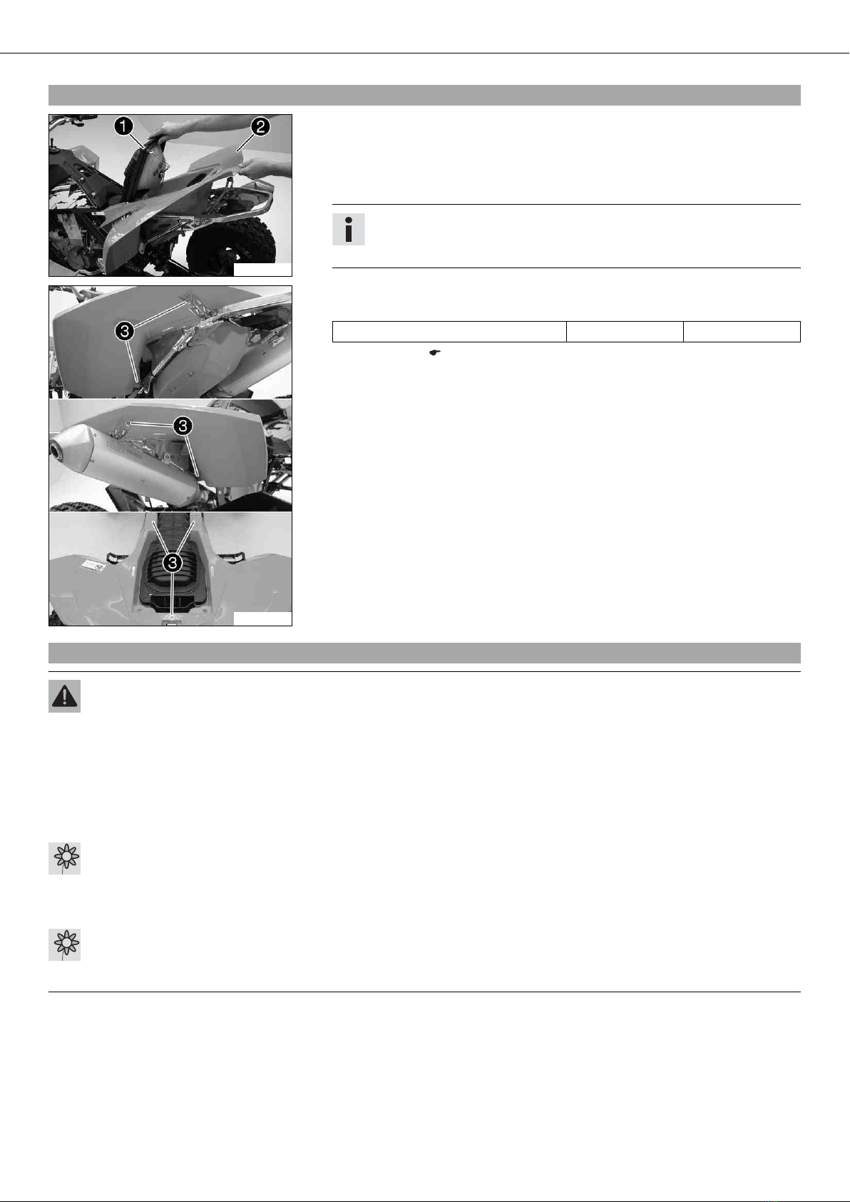
–Switch off all power consumers and switch off the engine.
–Remove the rear fender. ( p. 5)
–Disconnect the minus (negative) cable of the battery to avoid damage to the vehi-
cle's electronics.
100087-10
–Connect the battery charger to the battery. Switch on the battery charger.
Battery charger (58429074000)
You can also use the battery charger to test rest potential and start potential of the
battery, and to test the alternator. With this device, you cannot overcharge the bat-
tery.
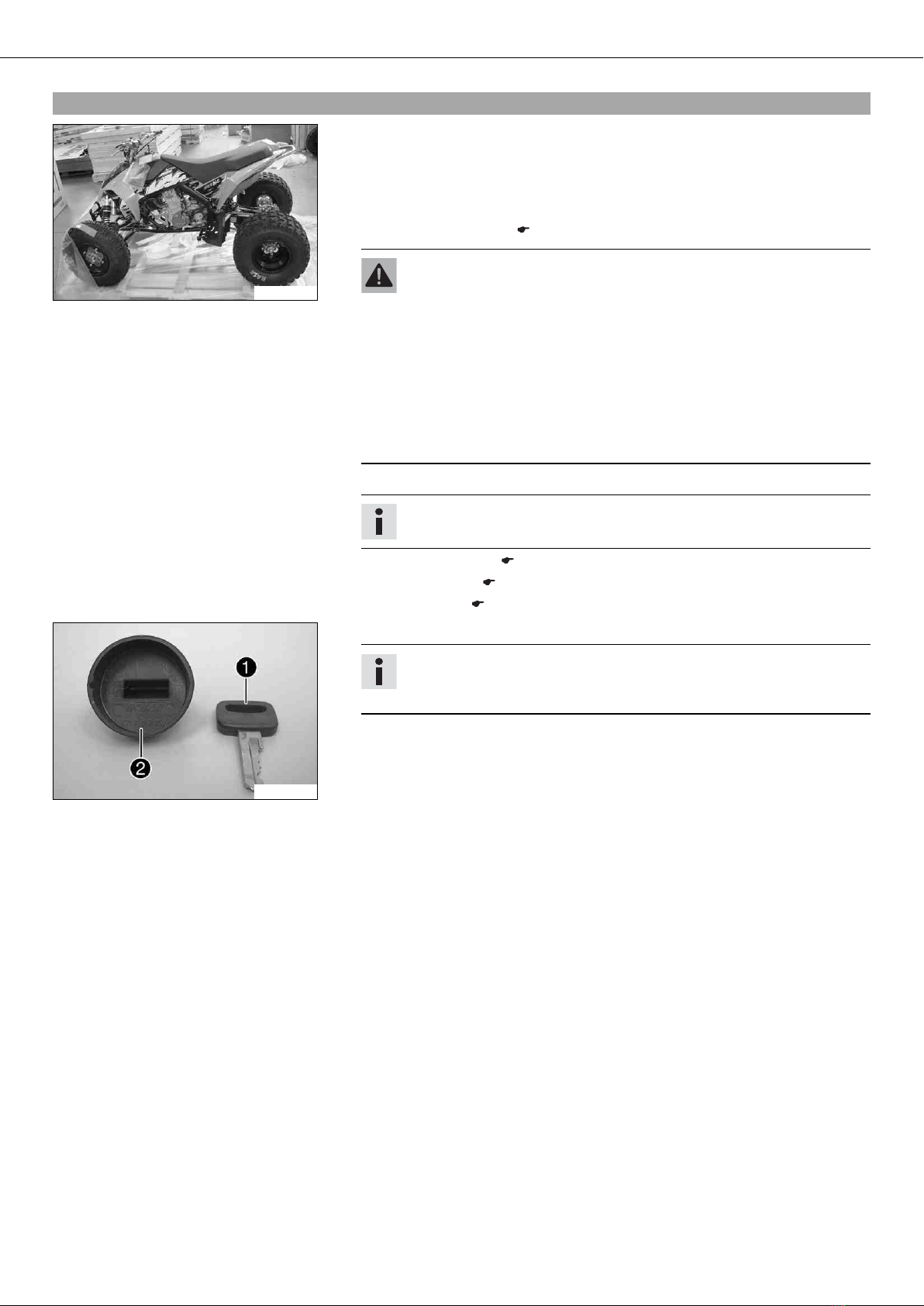
Info
Never remove the lid .
Charge the battery to a maximum of 10% of the capacity specified on the
battery housing .
–Switch off the charger after charging. Disconnect the battery.
Guideline
The charge current, charge voltage and charge time must not be exceeded.
Charge the battery regularly when the
vehicle is not in use
3 months
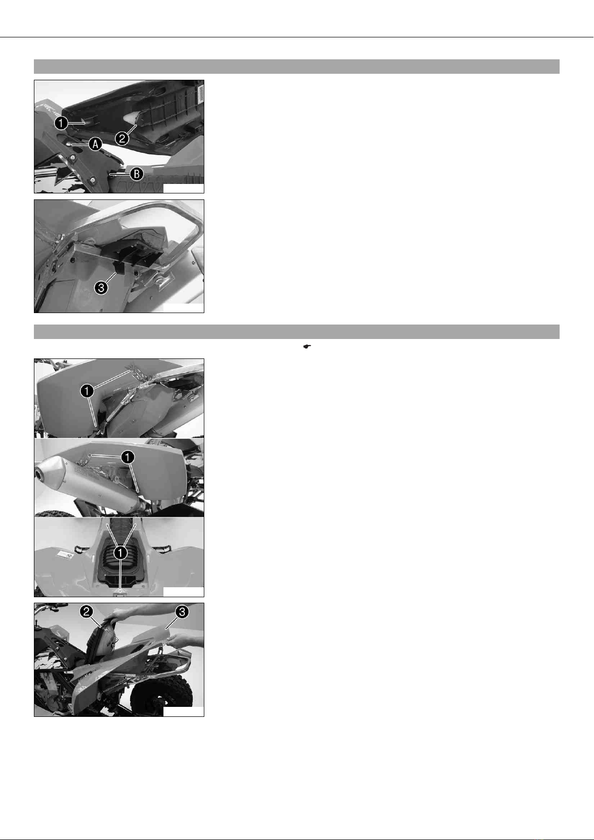
–Install the rear fender. ( p. 6)
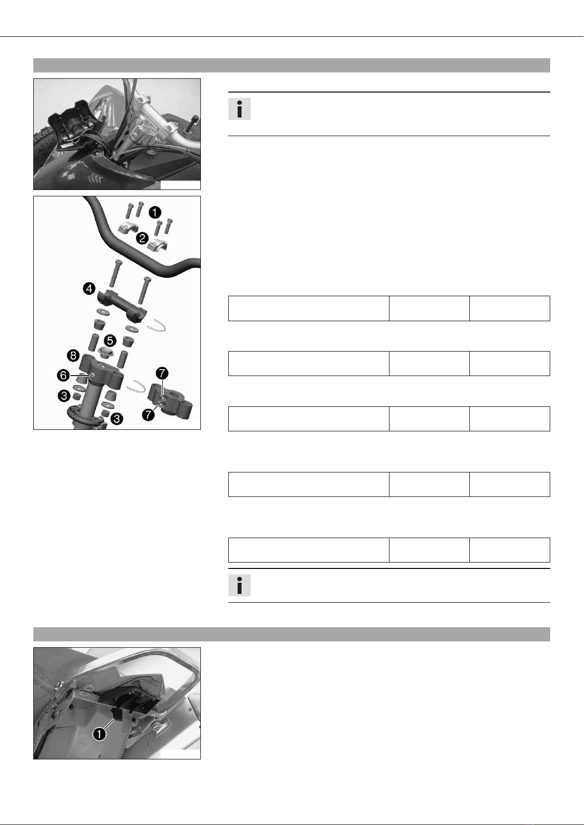
3.7Installing the battery
200150-11
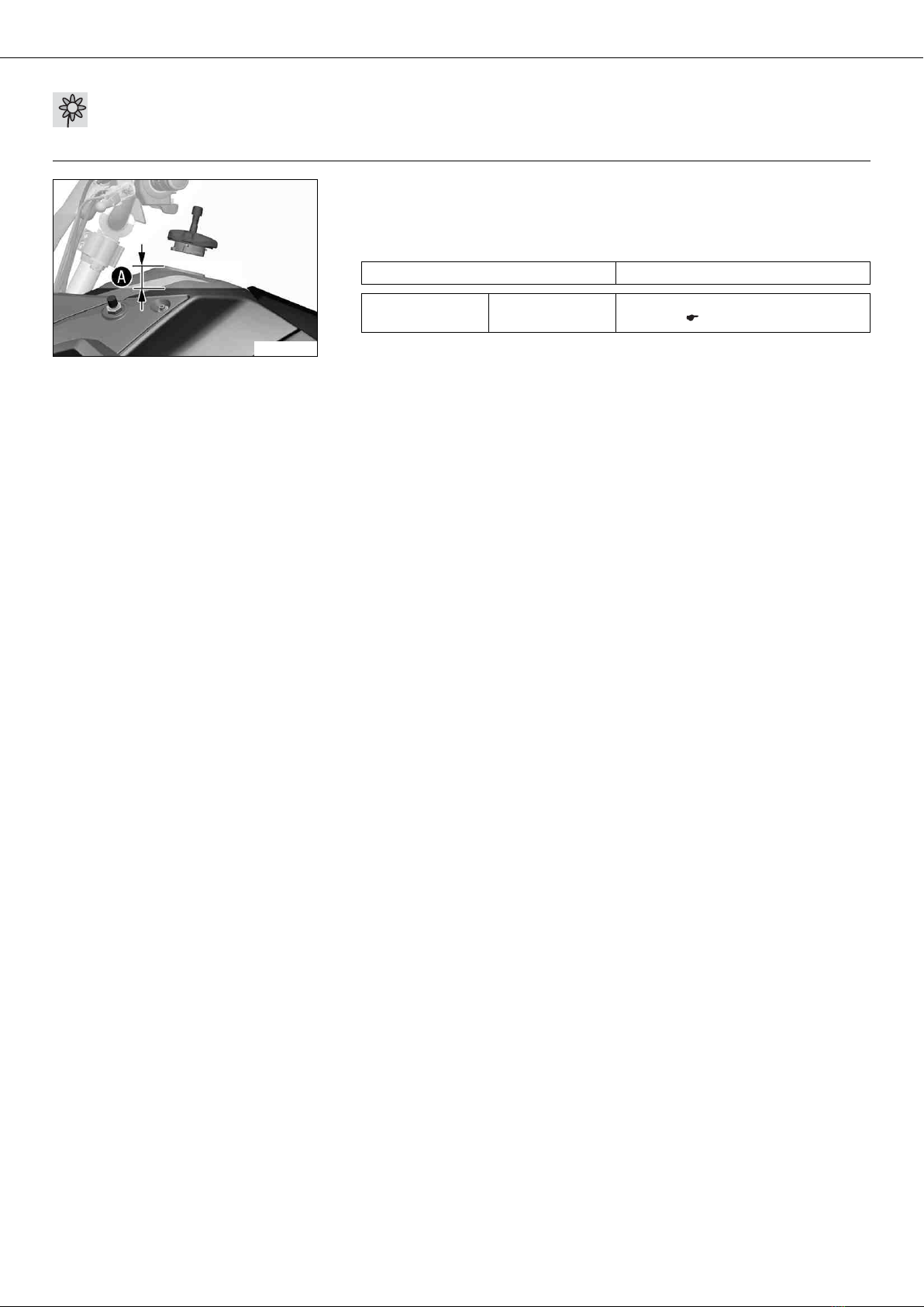
–Place the battery in the battery holder.
Battery (YTX5L-BS)
–Reconnect rubber band .
–Attach the positive (plus) cable and replace the plus pole cover .
–Connect the negative (minus) cable of the battery.
–Install the rear fender. ( p. 6)
3.8Refueling
Danger
Fire hazard Fuel is highly flammable.
–Never refuel the vehicle near open flames or burning cigarettes, and always switch off the engine first. Be careful that no
fuel is spilt, especially on hot vehicle components. Clean up spilt fuel immediately.
–Fuel in the fuel tank expands when warm and can escape if the tank is overfilled. See the notes on refueling.
Warning
Danger of poisoning Fuel is poisonous and a health hazard.
–Avoid contact of the fuel with skin, eyes and clothing. Do not inhale fuel vapors. If fuel gets into your eyes, rinse imme-
diately with water and contact a doctor. Wash affected skin areas immediately with soap and water. If fuel is swallowed,
contact a doctor immediately. Change clothing that has come into contact with fuel.