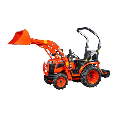
Kubota LA1353 Instruction manual

LA1153, LA1353, WSM
SAFETY
INSTRUCTIONS
SAFETY FIRST
This symbol,
the
industry's "Safety Alert Symbol", is used
throughout
this
manual and
on
labels on
the machine itself
to
warn
of
the
possibility
of
personal injury. Read these
instructions
carefully.
It
is
essential
that
you
read the
instructions
and safety regulations before
you
attempt
to
repair
or
use
this
unit.
• NOTE : Gives helpful information.
BEFORE SERVICING AND REPAIRING
• Read all instructions and safety instructions
in
this
manual and on your machine safety decals.
• Clean the work area and machine.
• Park the machine on a firm and level ground, and set
the parking brake.
• Lower the implement to the ground.
• Stop the engine. and remove the key.
• Disconnect the battery negative cable.
• Hang a
''~O
NOT OPERATE" tag
in
operator
station.
A DANGER : Indicates an imminently hazardous situation which,
if
not
avoided,
will
result in
death
or
serious injury,
A WARNING : Indicates a potentially hazardous situation which,
if
not
avoided,
could
result
in
death
or
serious injury.
ACAUTION : Indicates a potentially hazardous situation which,
if
not
avoided, may result in
minor
or
moderate injury.
• IMPORTANT : Indicates that equipment
or
property damage
could
result
if
instructions
are
not
followed.
1

LA1153.
LA1353.
WSM
SAFETY
INSTRUCTIONS
•
+ -
SAFETY STARTING
• Do not start the engine by shorting across starter
terminals or bypassing the safety start switch.
• Do not alter or remove any part of machine safety
system.
• Before starting the engine, make sure that all shift
levers are
in
neutral positions or in disengaged
positions.
• Never start the engine while standing
on
ground.
Start the engine only from operator's
seat
SAFETY WORKING
• Do not work
on
the machine while underthe influence
of alcohol, medication, or other substances or while
fatigued.
• Wear close fitting clothing and safety equipment
appropriate to the job.
• Use tools appropriate to the work. Makeshift tools,
parts, and procedures are not recommended.
• When servicing is performed together by two or more
persons, take care to perform all work safely.
• Do not work under the machine that
is
supported
solely by a jack. Always support the machine by
safety stands.
• Do nottouch the rotating or hot parts while the engine
is
running.
• Never remove the radiator cap while the engine is
running, or immediately after stopping. Otherwise, hot
water will spout out from radiator. Only remove
radiator cap when cool enough to touch with bare
hands. Slowly loosen the cap to first stop to relieve
pressure before removing completely.
• Escaping fluid (fuel or hydraulic oil) under pressure
can penetrate the skin causing serious injury. Relieve
pressure before disconnecting hydraulic or fuel lines.
Tighten all connections before applying pressure.
AVOID FIRES
• Fuel
is
extremely flammable and explosive under
certain conditions. Do not smoke or allow flames or
sparks
in
your working area.
• To avoid sparks from an accidental short circuit,
always disconnect the battery negative cable first and
connect it last.
• Battery gas can explode. Keep sparks and open
flame away from the top of battery, especially when
charging the battery.
• Make sure that no fuel has been spilled on the engine.
2
LA1153,
LA1353,
WSM
SAFETY
INSTRUCTIONS
VENTILATE WORK
AREA
•
If
the engine must be
running
to
do
some work, make
sure the area
is
well ventilated. Never
run
the engine
in
aclosed area. The exhaust gas contains poisonous
carbon monoxide.
PREVENT ACID
BURNS
• Sulfuric
acid
in
battery electrolyte
is
poisonous.
It
is
strong enough
to
burn
skin,
clothing
and
cause
blindness if splashed
into
eyes.
Keep electrolyte
away from eyes, hands
and
clothing.
If
you
spill
electrolyte
on
yourself,
flush
with water,
and
get
medical attention immediately.
DISPOSE
OF
FLUIDS PROPERLY
•
Do
not pour fluids into the ground, down a drain, or
into a stream, pond, or
lake.
Observe relevant
environmental protection regulations
when
disposing
of oil, fuel, coolant, electrolyte
and
other harmful
waste.
PREPARE
FOR
EMERGENCIES
• Keep a first aid kit and fire extinguisher handy
at
all
times.
• Keep emergency numbers for doctors, ambulance
service, hospital and fire department near your
telephone.
3

LA1153, LA1353, WSM
SAFETY
INSTRUCTIONS
SAFETY
DECALS
The
following safety decals are installed on the machine.
If a decal becomes damaged, illegible or is not on the machine, replace
it.
The decal part number is listed in
the
parts list.
(1) Part
No.
7J246-5641-1 (2) Part No. 7J246-5642-1
(3) Part
No.
7J417-7778-1
(M1858, M1859, M1864, M1865)
4FAAAAAAPOO2F
3FUAAAICP001A
4

LA1153, LA1353, WSM
SAFETY
INSTRUCTIONS
(1) Part NO.7J246-5645-1 (2) Part No. 7J246-5644-2
(Both sides)
(3)
(3) Part No. 7J266-5649-2 (4) Part No. 7J417-9321-1
(M1866)
1AIABCFAP050A
3FUAAAICP002A
5

LA1153,
LA1353,
WSM
SAFETY
INSTRUCTIONS
(1) Part No. 7J417-5643-1 (2) Part No. 75585-3619-3
A DANGER
(1)
1AIABBPAP0250
(3) Part No. 7J246-5643-1
-""'1-
__
1
A DANGER
CARE
OF
DANGER,
WARNING
AND
CAUTION LABELS
1.
Keep danger, warning and caution labels clean and free from obstructing material.
2. Clean danger. warning and caution labels with soap and water, dry with a soft cloth.
3.
Replace damaged or missing danger. warning and caution labels with new labels from your local KUBOTA
Dealer.
4.
If a component with danger, warning and caution label(s) affixed is replaced with new part, make sure new
label(s)
is
(are) attached
in
the same location(s) as the replaced component.
5.
Mount new danger, warning and caution labels by applying on a clean dry surface and pressing any
bubbles to outside edge.
3UFAAAICP003A
6

LA1153. LA1353. WSM
LOADER
TERMINOLOGY
LOADER TERMINOLOGY
3UFAAAIDP001
A
(9)
(1) Mounting Pin (4) Boom Cylinder (6) Boom (8) Bucket
(2)
Side Frame (5) Main Frame (7) Bucket Cylinder (9) Control Lever
(3) Hydraulic Control
Valve
7

LA1153, LA1353,
WSM
SPECIFICATIONS
W1029088
SPECIFICATIONS
• Suitable Tractor
LA1153: M5040, M6040, M7040
LA1353: M8540, M9540
[1] LOADER SPECIFICATIONS
Loader Model LA1153 LA1353 !
Tractor Model M7040 M9540
Wheel Base 2050 mm (80.7 in.) 2250 mm (88.6 in.)
Front Tires 9.5-24 12.4-24
Rear Tires 16.9-30 18.4-30 I
Boom Cylinder Bore
Stroke
60
mm
(2.36 in.)
570.5 mm (22.46 in.)
70 mm (2.76 in.)
606
mm
(23.9 in.)
Bucket Cylinder Bore
Stroke
60 mm (2.36 in.)
507.5 mm (19.98 In.}
65
mm
(2.56 In.)
512.5 mm (20.2 in.)
Control Valve One Detent Float Position, Power Beyond Circuit
Rated Flow
Maximum Pressure
42
Umin.
(11.1
U.S.gals/min., 9.2 Imp.gals/min.)
19.8 MPa (202 kgf/cm2
, 2873 psi)
64.3Umln.
(17.0 U.S.gals/min.,
14.1
Imp.gals/min.)
20.7 MPa
(211
kgf/cm2
, 3002 psi)
Net Weight (Approximate) 700 kg (1543 Ibs) 840 kg (1852 Ibs)
W1027852
[2] BUCKET SPECIFICATIONS
Loader Model LA1153 I LA1353
Model ROUND 72" ROUND 84" LIGHT MATERIAL
84"
Type Quick Attach
Width 1830
mm
(72.0 in.) 2135
mm
(84.0 in.)
(L) 650 mm (25.59 in.) 750 mm (29.53 in.)
Height (M) 665 mm (26.18 in.) 715 mm (28.15 in.)
Length (N) 900 mm (35.43 in.) 1000
mm
(39.37 in.)
Capacity Struck 0.44 m3 (15.5 cu.ft.) 0.52 m3 (18.4 cu.ft.) 0.63 m3 (22.3 cu.ft.)
Heaped 0.55 m3 (19.4 cu.ft.) 0.64 m3 (22.6 cu.ft.) 0.79 m3 (27.9 cu.ft.)
Weight 210
kg
(463Ibs) 235 kg (518Ibs) 255 kg (562 Ibs)
Wl013973
L
M
i 3UFAAABDP002A
8

LA1153, LA1353,
WSM
SPECIFICATIONS
[3]
DIMENSIONAL AND OPERATIONAL SPECIFICATIONS
~V
u v
B A
~XX
C w x
J
zz
G
y Z
3UFAAABDP003A
• Dimensional Specifications
Loader Model LA1153 LA1353
Tractor Model M5040,M6040,M7040 M8540, M9540
BOOM
CYLINDER
FULCRUM
POINT
HEIGHT
POWER
HEIGHT
POWER
(A)
Maximum lift
height
to
pivot
pin
3370
mm
(132.7 in.)
2977mm
(117.2 in.)
3700
mm
(145.7 in.)
3350
mm
(131.9 in.)
(B) Maximum lift
height
under
level
bucket
3131
mm
(123.3 in.)
2738
mm
(107.8 in.)
3420mm
(134.6 in.)
3090
mm
(121.7 in.)
(C) Clearance with
bucket
dumped
2577
mm
(101.5 in.)
2172
mm
(85.5 in.)
2808
mm
(110.6 in.)
2405
mm
(94.7 in.) i
J
(D) Reach
at
maximum
lift
height
I
(Dumping
Reach)
357mm
(14.1 in.)
811
mm
(31.9 in.)
738mm
(29.1 in.) 1149 mm
(45.2 in.)
(E) Maximum
dump
angle
0.75 rad (43
0)
1.047
rad
(60
0)
0.908
rad (52 ") 1.117 rad (64
0)
(F) Reach with
bucket
on
ground
1947
mm
(76.7 in.) 2233
mm
(87.9 in.)
(G) Bucket roll-back
angle
0.75 rad (43
0)
0.698 rad
(40
")
(H) Digging
depth
134
mm
(5.3 in.)
111
mm
(4.4 in.)
198
mm
(7.8 in.)
185
mm
(7.3 in.)
(J) Overall
height
in
carry
position 1573
mm
(61.9 in.) 1695
mm
(66.7 in.)
W1013874
• Operational Specifications
Loader Model
Tractor Model
BOOM
CYLINDER
FULCRUM
POINT
Lift capacity (Bucket
bottom
mid
point)
(U) Lift capacity
(Bucket
pivot
pin,
max.
height)
(V)
Lift capacity (800
mm
forward,
max.
height)
(W) Lift capacity
(Bucket
pivot
pin,
1500
mm
height)
(X) Lift capacity
(800
mm
forward,
1500
mm
height)
(Y) Breakout force
(Bucket
pivot pin)
(Z) Breakout
lorce
(800
mm
forward)
(W)
Bucket roll-back force
at
maxumum
height
(XX) Bucket roll-back force
at
1.5 m
(59
in.)
(ZZ) Bucket roll-back force at
ground
level
RaiSing time
Lowering time
i Bucket dumping
time
Bucket roll-back
time
LA1153
M5040, M6040, M7040
HEIGHT
POWER
1055 kg
(2326Ibs)
1150 kg (2536 Ibs)
1120 kg
(2469
Ibs) 1328 kg
(2928Ibs)
720
kg
(1587Ibs)
830 kg (1830 Ibs)
1456
kg
(3210 Ibs) 1672
kg
(3686 Ibs)
1010
kg (2227 Ibs) 1200
kg
(2646 Ibs)
18816
N (4230 Ibl)
23814
N (5354 Ibl)
12054
N (2710 Ibl)
15190
N
(3415Ibl)
8722 N (1961 Ibf)
12054
N (2710 Ibl)
16072 N (3613 Ibl) 16611 N (3734 Ibf)
15288
N (3437 Ibl)
16415
N (3690 Ibf)
4.7 sec.
3.6 sec.
3.0 sec.
2.8 sec.
LA1353 i
M8540, M9540 i
HEIGHT
POWER
1300 kg
(2866Ibs)
1350
kg
(2976Ibs)
1810
kg
(3990 Ibs) 1880
kg
(4144Ibs)
1145
kg
(2524 Ibs)
1295
kg (2855 Ibs) I
2070
kg
(4563Ibs)
2330
kg (5137 Ibs) J
1535
kg
(3384 Ibs) 1795
kg
(3957Ibs)
i
,
24470
N (5501 Ibl)
28780
N (6470 Ibf) !
16920 N (3804 Ibf)
21850
N (4912 Ibl)
12150
N (2731 Ibf)
14460
N (3250 Ibl)
23415
N (5264 Ibl) i
23365
N (5252 Ibl)
4.2 sec. i
2.9 sec. I
2.2 sec.
2.4
sec.
W1030299
9


MECHANISM
CONTENTS
1.
CONTROL VALVE ASSEMBLY
(LA
1153 STANDARD VALVE).................
M-1
[1] HYDRAULIC CiRCUiT..............................................................................
M-1
[2]
STRUCTURE .............................................................................................
M-2
[3]
OPERATION..............................................................................................
M-3
[4]
RELIEF VALVE .........................................................................................M-9
2.
CONTROL VALVE ASSEMBLY (LA1353 STANDARD VALVE)............... M-10
[1] HYDRAULIC CiRCUiT............................................................................M-10
[2]
STRUCTURE...........................................................................................
M-11
[3]
OPERATION............................................................................................M-12
[4]
RELIEF VALVE .......................................................................................M-18
3.
SELF-LEVEL VALVE ....................................................................................
M-21
[1] HYDRAULIC CiRCUiT............................................................................
M-21
[2]
STRUCTURE...........................................................................................M-22
[3]
OPERATION ............................................................................................M-23
[4]
RELIEF VALVE .......................................................................................M-63
(1) Main Relief Valve ...............................................................................M-63
(2)
Overload Relief Valve ........................................................................M-64
4.
BOOM CYLINDER
AND
BUCKET CyLINDER..........................................M-66


LA
1153,
LA
1353,
WSM
FRONT LOADER
1. CONTROL VALVE ASSEMBLY (LA1153 STANDARD
VALVE)
[1]
HYDRAULIC CIRCUIT
11)~
(2)
(3)""
I
A1
B1
A2
B2
~------------------
i
(4) i
i
i
i
i
pi
~
________
~~~Q=~±===-cc=~==~
____
~
-+
i i
P.B.
i i
i i
i i
i
L_________________
_
___________
j
i
3UFAAAILP029A
(5)
(6)
To
operate the front loader,
the
hydraulic oil
pressurized
by
the
hydraulic
pump
flows
from
P portthrough
the
boom
control valve (5)
and
the
bucket
control valve (6)
to
P.B.
port
or
T port.
(1) Boom Cylinder (4) Relief Valve
P:
From
Pump
A1
:
A1
Port
(2) Bucket Cylinder (5) Boom Control Valve
T:
ToTank
A2:
A2
Port
(3) Control Valve Assembly (6) Bucket Control Valve P.B.:
To
3-Point
Hydraulic
B1
:
B1
Port
System
B2:
B2 Port
M-1

LA1153,
LA1353,
WSM
FRONT LOADER
[2]
STRUCTU
RE
(1
)
(4)
(2)
A1
B1
1------------'
i
i
i
i
i
i
i
A2 B2
p~ir-~~~T---~~~--------.
"
P.B.
(3)
(2) (3)
3UFAAAILP022A
(1) Inlet and Outlet Section
P:
P Port
A1
:
A1
Port
B1
:
B1
Port
(2) Boom Control Valva
T:
T
Port
A2:
A2 Port
B2:
B2 Port
(3) Bucket Control Valve
P.B.
:P.B. Port
(4) Power Beyond
The control valve assembly is composed of one casting block and four major section as shown above.
(1) Inletand
Outlet
Section
This section has P and T ports.
The P port is connected to the OUTLET port of hydraulic block by the hydraulic hose.
The T port is connected to the
TANK
port of hydraulic block bythe hydraulic hose.
(2) Boom
Control
Section
The boom control valve is of 4-position, 6-connection, detent, spring center type, conSisting of a mono block valve
housing, spool, load check valve, etc. This valve has A1 and
B1
ports and controls oil flow to the boom cylinder.
(3) Bucket
Control
Section
The bucket control valve is of 3-position, 6-connection, no detent, spring center type, consisting of a mono block
valve housing, spool, load check valve, etc. Thisvalve has
A2
and B2 ports and controls oil flow to the bucket cylinder.
(4) Power
Beyond
This section has P.B. port which is connected to the INLETport of hydraulic block bythe hydraulic hose, and feeds
oil to the three point hydraulic control valve.
M-2

lAl153,
LA1353, WSM
FRONT
LOADER
[3] OPERATION
• Neutral
p
r-----------;f:-------------'------,
i
i
I
i
i
i
(7) I
I
I
I
I
!
I
1...-
_______
_
(1
)
(2)
(3) A2 (6)
82
: (8)
3UFAAAllP023A (7)
(1)
Boom Control Section (5)
P.B.
Passage 1
T;
T Port
B1
:
B1
Port
(2) Bucket Control Section
(6)
P.B. Passage 2
P:
P Port
B2;
B2 Port
(3)
Spool (7)
load
Check
Valve
A1
:
A1
Port P.B.:P.B. Port
(4) Spool
(8)
Relief Valve
A2:
A2 Port (8) Low Pressure
M-3

LA1153, LA1353,
WSM
FRONT
LOADER
• Up
3UFAAAILP024A
~,u..w..u......L.I.w
I
i (1)
i
j
I
I
!
I...-~---~------
P.B.
-
-
T
0:(8)
i
i
i
i
i
iA1
iB1
i
_E+-
i
....
j
(1)
(2)
.:(b)
P
r----------- ----------------.,
i
I
i
~
(1) Boom Control Section (5) Neutral Passage 1
P:
P
Port
A1
:
A1
Port
(2) Bucket Control Section (6) Load Check Valve
T:
T Port (From Boom Cylinder)
(3) Spool (7) Passage 1
B1
:
B1
Port
(To
Boom
Cylinder)
(4)
P.B.
Passage 1 (8) Boom Cylinder P.B.:
P.B.
Port
a:
Low
Pressure
b : High Pressure
1.
When the hydraulic control lever is set to the
"UP"
position, the spool (3) of the boom control section (1) moves to
the left, which forms oil passages between passage 1 (7) and
61
port, and between A1 port and P
.6.
passage 1
(4).
2. As the oil passage from the neutral passage 1 (5) to the
PB
passage 1 (4)
is
closed by the spool (3), the pressure-
fed oil from the P port opens the load check valve (6) and flows through the notched section of the spool (3) and
B1
port to extend the boom cylinder (8).
3. Return oil from the boom cylinder (8) flows from the A1 portthrough
the
passage in the spool (3) and P
.6.
passage
1 (4) to the bucket control section (2).
M-4

LA1153,
LA1353,
WSM
FRONT LOADER
•
Down
P.B.
i
i
!
I
i
i
I
L-
_________
_
P.B.
-i
i
i
j
i
A1
i
B1
i
i
I
P
r---------- --------------ji
I
!
I
i
I~
(8)
I
: (a)
_:(b)
•
3UFAAAILP025A
(1)
Boom
Control Section (5) Neutral Passage 1
P:
P Port A1 : A1 Port (To Boom Cylinder)
(2)
Bucket
Control Section (6) Load Check
Valve
T:
T Port
B1
:
B1
Port
(3)
Spool
(7)
Passage 1 (From Boom Cylinder)
(4)
P.B.
Passage 1
(8)
Boom Cylinder P.B.:
P.B.
Port
a :
Low
Pressure
b : High Pressure
1.
When the hydraulic control lever is set to the
"DOWN"
position, the spool
(3)
moves to the right, which forms oil
passages between passage 1 (7) and
A1
port, and between
B1
port and
P.B.
passage 1 (4).
2.
As the oil passage from the neutral passage 1 (5) to the PB passage 1
(4)
is closed by the spool (3), the pressure-
fed oil from the P port opens the load check valve (6) and flows through the notched section of the spool (3) and
A1
port to retract the boom cylinder (8).
3.
Return oil from the boom cylinder (8) flows from
the
B1
port through the passage in the spool (3) and P.B. passage
1
(4)
to the bucket control section (2).
M-5

LA
1153,
LA
1353,
WSM
FRONT
LOADER
• Floating
3UFAAAILP026A
r-----------
i
!
I
i
i
I
i
I
i
I
i
j
L..-~
______
_
P
---------------l
P.B.
-
I
j
j
i
!A1
jB1
i
"j!t'J--l--
l !
T
(1
)
1>,1:(a)
(1)
Boom
Control Section (5) Detent Mechanism
P:
P
Port
A1
:
A1
Port
(2)
Bucket Control Section (6) Neutral Passage 1
T:
T
Port
B1
:
B1
Port
(3)
Spool
(7)
Boom Cylinder P.B.:
P.B.
Port
(4)
P.B.
Passage 1 a :
Low
Pressure
1.
When the hydraulic control lever
is
set to the
"FLOAT"
position, the spool
(3)
moves further to the right from the
"DOWN"
position and is retained by the detent mechanism (5).
2.
This forms oil passages among the A1 port,
B1
port and T port. As a result, oil
in
the boom cylinder
(7)
flows freely
from the A1 port and
B1
port through the T port to the transmission case.
3.
Oil entering the P port flows to the bucket control section (2) through the neutral passage 1 (6) and P.B. passage
1 (4).
M-6

LA1153,
LA
1353,
WSM
FRONT LOADER
•
Roll-back
P
r·_·_·_·_·_·-$-_·_·_-_·_·_·
__
·_··....,
i
i
i
i
i
I
!
I i
(9)
(1
)
(2)
3UFAAAILP027A : (a)
.:(b)
!II
.....
=~J.=J.;-w
I
_
!A2
i
II~--~--~~~~
I -
iB2
L--~
___
,.
___
_
P.B.
T .J
(1)
Boom Control Section
(6)
P.B.
Passage 2
P:
P
Port
B2:
B2
Port
(2)
Bucket Control Section
(7)
Load Check Valve
T:
T Port (To
Bucket
Cylinder)
(3) P.B. Passage 1
(8)
Passage 2 P.B.:
P.B.
Port 8 :
Low
Pressure
(4) Spool (9) Bucket Cylinder
A2:
A2
Port b :
High
Pressure
(5) Neutral Passage 2 (From
Bucket
Cylinder)
1.
When
the hydraulic control lever is set to the
"ROLL-BACK"
position. the spool (4) of the bucket control section
(2) moves
to
the left, which forms oil passages between passage 2 (8) and
B2
port, and between
A2
port and T
port.
2.
The
pressure-fed oil from the P port flows to the neutral passage 2 (5) through the boom control section (1) and
P.B. passage 1 (3). As the oil passage from the neutral passage 2 (5) to the P.B. passage 2 (6) is closed
by
the
spool (4). this oil opens the load check valve (7). and flows through the notched section
of
the spool (4) and
B2
port
to
retract the bucket cylinder (9).
3.
Return oil from the bucket cylinder (9) flows to the transmission case through the
A2
port and T port.
M-7

lA1153, lA1353,
WSM
FRONT
LOADER
•
Dump
P
r-----------
-~-~-
..
-~-~----
..
....,
i
!
I i
i i
i i
i !
i
!
!
I (1) i
(9)
1)
(2)
_:(b)
3UFAAAILP028A
(1) Boom Control Section (6)
P.B.
Passage 2
P:
P Port
A2:
A2 Port
(2) Bucket Control Section (7) Load Check Valve
T:
TPort
(To BucketCylinder)
(3)
P.B.
Passage 1 (8) Passage 2
P.B.:
P.B.
Port
B2:
B2 Port
(4) Spool (9) Bucket Cylinder (From Bucket Cylinder)
(5) Neutral Passage 2
b:
High Pressure
(7)
i
i
i
i
i
L
__
___
..
__
-
~_~
P.B.
-I
i
iA2
iB2
__
J
T
1. When the hydraulic control lever
is
set to the
"DUMP"
position, the spool (4), which forms oil passages among
passage 2 (8),
A2
port and
82
port.
2. The pressure-fed oil from the P port flows to the A2 port just like the
"DUMP"
position.
3.
Return oil from the bucket cylinder (9) flows from the
82
port
to
the passage 2 (8), and flows to the
A2
port together
with the pressure-fed oif from the P port.
As a result, the dump speed is increased.
(Reference)
• The oil pressure of the
A2
port and
82
port is identical, butthe bucket cylinder extend bythe difference of received
pressure area (cylinder rod part).
M-8
This manual suits for next models
1
Table of contents
Other Kubota Front End Loader manuals

Kubota
Kubota LA434 User manual

Kubota
Kubota R540 User manual

Kubota
Kubota LA344 Instruction manual

Kubota
Kubota LA1954 User manual

Kubota
Kubota LA525 Instruction manual

Kubota
Kubota LA534 User manual

Kubota
Kubota WSM LA1403 User manual

Kubota
Kubota BX2370 Instruction manual

Kubota
Kubota LA535 User manual

Kubota
Kubota LA513 User manual