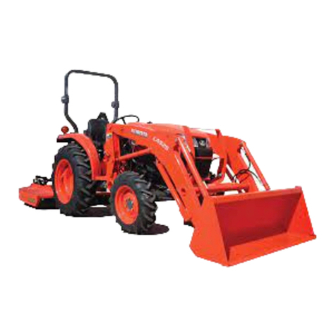
Kubota LA213 User manual


CONTENTS
ASSEMBLY INSTRUCTIONS ..................................................................................... 1
TO THE DEALER..................................................................................................... 1
SAFETY ................................................................................................................... 1
UNPACKING AND CHECKING PARTS .................................................................. 2
Unpacking Wooden Crate................................................................................................. 2
Checking Parts .................................................................................................................3
TRACTOR PREPARATION ..................................................................................... 4
ASSEMBLY.............................................................................................................. 4
Main Frames.....................................................................................................................4
Sub Frames ......................................................................................................................4
Bucket, Bucket Cylinder and Boom ..................................................................................5
Hydraulic Line ................................................................................................................... 6
Relocating the Front Combination Light ........................................................................... 8
Front Guard ...................................................................................................................... 9
Tightening Bolts and Nuts............................................................................................... 10
PRE-OPERATION CHECK.................................................................................... 10
Lubrication ...................................................................................................................... 10
Transmission Fluid.......................................................................................................... 10
Rear Ballast ....................................................................................................................11
Liquid Ballast in Rear Tires.............................................................................................11
Tire Inflation.................................................................................................................... 11
Inflation Pressure............................................................................................................ 11
Test Operation ................................................................................................................ 12
Removing Air from Hydraulic System.............................................................................12
TIGHTENING TORQUE OF BOLTS AND NUTS .................................................. 13

1ASSEMBLY INSTRUCTIONS
ASSEMBLY INSTRUCTIONS
TO THE DEALER
1. This manual contains procedures intended to assist
the dealer in unpacking and assembling the product
before delivering to the customer.
The customer's purchase is based on confidence in
both the product and your store. Observe the
procedures in this manual to assemble and adjust
equipment for your customer's safety and satisfaction.
When fully assembled, check function of each part and
feature.
2. The following safety alert symbol marks and
indications are found throughout this manual in steps
where particular attention is required so as to ensure
your safety and to avoid product damage. Observe
the instructions in these warnings where indicated.
SAFETY
To prevent accidents, read through the following items
before starting work, and always regard safety when
working. It is your responsibility to ensure your safety on
the job.
1. Preparations
(1) Select a work site which is level, has sufficient
space, and is not close to dangerous objects.
(2) Avoid poorly ventilated
rooms.
Asphyxiation from exhaust
fumes is always a possibility
that accompanies running an
engine.
(3) Working clothes which may
be pinched or caught in the
equipment must not be worn.
Loose clothing can cause
serious injury or death.
(4) Always wear a mask and
protective goggles during
work when dust or flying
debris may be thrown by
equipment.
2. Assembly and adjustments
(1) Before assembling
equipment, read the
assembly instructions for the
product to become familiar
with the equipment and
procedures.
(2) Use only adequate and
required equipment, tools
and instruments (e.g. torque
wrench, battery hydrometer
and etc.).
(3) Set the parking brake and
block wheels to prevent
machine (or tractor)
movement.
(4) Lower the attachment or
implement to the ground
before assembling or
adjusting equipment.
(5) Before working under
suspended or raised
equipment, support the
equipment or attachment
and utilize the valve lock to
prevent the machine from
falling or moving out of place.
(6) Keep fire from cigarettes,
matches or other ignition
sources away from fuel, oil,
antifreeze and other
flammable materials.
Indicates an imminently
hazardous situation which, if not
avoided, will result in death or
serious injury.
Indicates a potentially
hazardous situation which, if not
avoided, could result in death or
serious injury.
Indicates a potentially
hazardous situation which, if not
avoided, may result in minor or
moderate injury.
Indicates that equipment or
property damage could result if
instructions are not followed.
Gives helpful information


ASSEMBLY INSTRUCTIONS2
3. After assembly check
(1) Before operating or test driving the equipment,
read and understand the operator's manual.
(2) Once the equipment is fully
assembled, select a safe
place for a test run. Prevent
onlookers from approaching
the equipment.
To avoid personal injury or
death:
ADo not start engine or
operate levers from
anywhere other than the
seat.
To avoid personal injury:
ADo not bypass-start the
equipment. Short circuiting
the starter terminal runs the
risk that the equipment will
start operating or moving
unexpectedly.
UNPACKING AND CHECKING PARTS
BUnpacking Wooden Crate
1. Cutting metal bands (if two are banded together).
Metal bands hold the two crates together as one. Cut
these bands and separate the crates.
2. Unpacking the crates
(1) Hook a hoist to the 4 corners of the crate and raise
the hoist cable until taut.
This serves to prevent the upper part of the crate
from striking the loader when cut.
(2) Saw the crate as indicated in figure 1.
ASawing outside the indicated area may damage the
loader or accessory parts.
ABe sure that the crate is free of other obstructions (e.g.
nails, staples and etc.).
(3) Raise the upper part of the crate and remove from
the immediate area.
(4) Remove the remaining slats from the crate. These
are indicated by the oblique lines in
Figure 1...

3ASSEMBLY INSTRUCTIONS
BChecking Parts
Remove all loader components. Referring to the illustration, insure that all components have been included.
(1) Boom assembly
(2) Main frames
(3) Bucket
(4) Main frame connector
(5) Front guard
(6) Sub frames
(7) Hydraulic block
(8) Control valve assembly
(9) Winker stays
(10) Parts box

ASSEMBLY INSTRUCTIONS4
TRACTOR PREPARATION
Locate the tractor on a firm level surface. Stop the engine.
ASSEMBLY
ADo not tighten any bolts firmly until most components
are attached to the tractor.
ABefore finally tightening all mounting hardware, start
the engine and apply down pressure to the bucket until
the loader takes the tractor weight off the front wheels
- do not lift the wheels off the ground. Make sure that
the mounting pins can be rotated easily.
Torque all bolts and nuts in this position.
ATo avoid damage to hoses, adjust all connections to
route hoses away from sharp edges.
AAssemble on the surface, preferably concrete.
BMain Frames
1. Attach the main frame to the tractor.
2. Attach the main frame connector as shown.
ADo not tighten until all components are assembled.
BSub Frames
1. Disconnect the set pin, lower link, and collar from the
lower link pin and remove the bolt.
(1) Main frame
(2) 4-M14 x 60 bolts
4-M14 spring washers
4-M14 plain washers
(3) 4-M12 x 45 sems bolts
4-M12 plain washers
(4) 4-M12 x 55 bolts
4-M12 nuts
4-M12 spring washers
4-M12 plain washers
Tightening torque: 90.1 N-m (9.2 kgf-m) (M12)
147 N-m (15.0 kgf-m) (M14)
(1) Main frame connector
(2) 4-M14 x 50 bolts
4-M14 spring washers
Tightening torque : 147 N-m (15 kgf-m)
(1) Set pin
(2) Lower link
(3) Collar
(4) Lower link pin
(5) Bolt

5ASSEMBLY INSTRUCTIONS
2. Attach the sub frame as shown below and then
reinstall the collar, lower link, set pin to the lower link
pin.
[Rear]
[Front]
BBucket, Bucket Cylinder and Boom
1. Attach the bucket to the boom assembly.
2. Attach the bucket cylinder as shown.
3. Remove the spring pin holding the stand to the boom.
4. Slide the stand leftward and rotate it until the hole in
the stand and pin on the boom are aligned.
Then slide the stand rightward and insert the spring pin
as shown.
(1) Sub frame
(2) 4-M12 x 50 bolts
(3) Lower link
(4) Collar
(5) Lower link pin
(6) Set pin
(1) Sub frame
(2) 6-M14 x 45 bolts
6-M14 nuts
6-M14 spring washers
(1) 2-pin 4
2-M6 x 45 bolts
2-M6 locking nuts
(2) Bucket cylinder
(3) Pin 3
M8 x 60 bolt
M8 locking nut
(1) Stand
(2) Spring pin

ASSEMBLY INSTRUCTIONS6
5. Attach the boom assembly to the main frame.
Then install mounting pins and secure them with the
locking rods.
AAfter installing the bucket to the boom, re-tighten the
elbow fitting of the hose 10. This fitting may loosen by
the movement of the bucket cylinder while shipping.
Tightening torque of 9/16 hose fitting : 22 to 25 N-m
(2.2 to 2.6 kgf-m, 16 to 19 ft-lbs)
BHydraulic Line
1. Remove the cover of the hydraulic block on the tractor.
2. Install the loader hydraulic block to the tractor
hydraulic block.
AMake sure to install the O-rings at the hydraulic block
cover.
AReuse the bolts fastening the hydraulic block cover.
Tightening torque : 23.0 N-m (2.35 kgf-m)
3. Detach the seat under cover and remove the plug from
the transmission case.
Install the return fitting to the transmission case.
AUse teflon tape on the tapered thread of the return
fitting.
(1) Hose 10
(2) Elbow fitting
(3) Bucket cylinder
(1) Hydraulic block
(2) 2-M8 bolts (Reuse)
(A) Pump port
(B) Power beyond port

7ASSEMBLY INSTRUCTIONS
4. Connect hose 7 to the return fitting as shown.
5. Attach the valve assembly to the main frame as
shown.
6. Route hose 5 from the power beyond port of the
hydraulic block to the power beyond port of the
hydraulic control valve.
7. Route hose 6 from the pump port of the hydraulic block
to the pump port of the hydraulic control valve.
(1) Hose 7
(2) Return fitting
(1) Main frame
(2) Valve assembly
(3) 3-M12 x 35 bolts
3-M12 nuts
3-M12 spring lock washers
(1) Hydraulic block
(2) Hose 5 (power beyond)
(3) Hose 6 (pump)
(A) Power beyond port
(B) Pump port
(1) Hydraulic control valve
(2) Hose 5 (power beyond)
(3) Hose 6 (pump)
(4) Hose 7
(A) Power beyond port
(B) Pump port
(C) Tank port

ASSEMBLY INSTRUCTIONS8
8. Clamp three hoses with plastic tie as shown.
AHoses pre-installed on the control valve assembly are
not securely tightened to ease installation. Be sure to
securely tighten all hose fittings after installing.
ATurn the hose fittings so the hoses clear the tractor
and tractor parts.
BRelocating the Front Combination Light
1. Remove the front combination light and nuts from the
plate and then detach the plate from the tractor
removing the bolts.
2. Remove the grommet from the tractor.
3. Insert the grommet into the hole of the winker stay.
4. Attach the winker stay to the main frame and then
install the front combination light to the winker stay as
shown below.
(1) Hoses
(2) Plastic tie
(1) Front combination light
(2) 2-M6 nuts
(3) Plate
(4) 2-M6 x 14 bolts
(5) Grommets
(1) Winker stay (RH)
(2) Grommet
(3) 2-M8 x 25 bolts
2-M8 nuts
(4) Front combination light
(5) 2-M6 nuts

9ASSEMBLY INSTRUCTIONS
5. Connect the wire harness and clamp them with the
plastic tie.
BFront Guard
Attach the front guard to the front axle frame of tractor.
Tightening torque : 90.1 N-m (9.2 kgf-m)
(1) Winker stay (LH)
(2) Grommet
(3) 2-M10 x 25 sems bolts
(4) Front combination light
(5) 2-M6 nuts
(1) Wire harness
(2) Plastic tie
(1) Front guard
(2) 3-M14 x 30 hex. bolts
(3) 3-M14 spring lock washers
(4) M14 hex. bolt
(5) M14 hex. nut
(6) M14 spring lock washer

ASSEMBLY INSTRUCTIONS10
BTightening Bolts and Nuts
Tighten all bolts and nuts with required torque.
ABefore finally tightening all mounting hardware, start
the engine and apply down pressure to the bucket until
the loader raises the front wheels slightly, and make
sure that the mounting pins can be rotated easily.
Tighten all bolts and nuts in this position.
PRE-OPERATION CHECK
BLubrication
Lubricate all grease fittings with SAE multipurpose
grease.
BTransmission Fluid
Check tractor transmission fluid level. Add fluid if
necessary. Refer to the tractor's Operator's Manual for
instructions and proper fluid. Repeat this check after
purging air from the system. At that time, it will be
necessary to add transmission fluid.
ATo check tractor transmission fluid level, lower the
bucket to the ground and lower the 3 point hitch.
Location Bolt / Nut Required Torque
Main frame
Sub frame
M14 bolts or nuts 147 N-m
(15.0 kgf-m)
M12 bolts or nuts 90.1 N-m
(9.2 kgf-m)
(1) Dipstick (Rear) (A) Oil level is acceptable within this range.
(1) Oil inlet

11ASSEMBLY INSTRUCTIONS
BRear Ballast
To avoid personal injury:
AFor tractor stability and operator's safety, rear
ballast should be added to the rear of the
tractor in the form of 3-point counter weight
and rear wheel ballast. The amount of rear
ballast will depend on the application.
BLiquid Ballast in Rear Tires
Water and calcium chloride solution provides a safe and
economical ballast. Used properly, it will not damage
tires, tubes or rims. The addition of calcium chloride is
recommended to prevent the water from freezing. Use of
this method of weighting the wheels has full approval of
the tire manufacturers. See your tire dealer for this
service.
Liquid weight per tire (75 Percent filled)
ADo not fill tires with water or solution more than 75% of
capacity (to the level of valve stem at 12 o'clock
position).
AWhen mounting a heavy implement, a liquid in the tire
may not be required.
ADo not add liquid ballast or any other weights to the
front tires.
BTire Inflation
Ensure that the tractor tires are properly inflated.
Refer to the tractor's Operator's Manual for optional tires.
BInflation Pressure
Implement as Counter Weight
Box Blade
Approx. 190kg
Rear Blade
Rotary Tiller
Ballast Box
Tire sizes 7-16 8-16 9.5-16
Slush free at -10
Solid at -30
[Approx. 1 kg CaCl per 4 L of
water]
26 kg 35 kg 54 kg
Slush free at -24
Solid at -47
[Approx. 1.5 kg CaCl per 4 L
of water]
28 kg 37 kg 57 kg
Slush free at -47
Solid at -52
[Approx. 2.25 kg CaCl per 4 L
of water]
29 kg 39 kg 60 kg
(1) Air
(2) Water
(A) Correct: 75% Full
Air compresses like a cushion
(B) Incorrect: 100% Full
Water can not be compressed
Tire sizes Inflation Pressure
Rear
7-16, 4PR 180 kPa (1.8 kgf/cm )
8-16, 4PR 160 kPa (1.6 kgf/cm )
9.5-16, 4PR 140 kPa (1.4 kgf/cm )
212/80D-15, 4PR 160 kPa (1.6 kgf/cm )
29x12.00D-15, 4PR 140 kPa (1.4 kgf/cm )
Front
4.50-10, 4PR 220 kPa (2.2 kgf/cm )
6-12B, 4PR 200 kPa (2.0 kgf/cm )
5-12, 4PR 240 kPa (2.4 kgf/cm )
20x8.00-10, 4PR 160 kPa (1.6 kgf/cm )
205x8.00-10, 4PR 160 kPa (1.6 kgf/cm )

ASSEMBLY INSTRUCTIONS12
BTest Operation
To avoid personal injury:
AKeep engine speed at low idle during the test
operation.
AEscaping hydraulic fluid under pressure can
have sufficient force to penetrate skin, causing
serious personal injury.
Before disconnecting lines, be sure to relieve
all pressure.
Before applying pressure to system, be sure all
connections are tight and that lines, tubes and
hoses are not damaged.
Fluid escaping from a very small hole can be
almost invisible. Use a piece of cardboard or
wood, rather than hands to search for
suspected leaks.
If injured by escaping fluid, see a doctor at
once. Serious infection or allergic reaction will
develop if proper medical treatment is not
administered immediately.
AWhen the lever is at each corner position marked by
asterisk (*), boom and bucket cylinders work at the
same time. However, the blank position (Raise & Roll
back) is not recommended for scooping because of
insufficient lift force.
To begin test operation, slightly move the control lever
from "N" position. Slowly raise the loader boom just
enough for the bucket to clear the ground when fully
dumped. Slowly work through the dump and roll back
cycles.
AIf the boom or bucket does not work in the directions
indicated on the label, lower the bucket to the ground,
stop the engine, and relieve all hydraulic pressure.
Recheck and correct all hydraulic connections.
This control valve has two stage dump positions. The first
"Regenerative" dump position, activated by moving the
lever to the right, features high speed for efficient normal
loader operations.
The second "Regular" dump position, activated by moving
the lever further to the right, features increased power.
This second position should be used when operating
implements other than the loader with this control valve.
These two positions are separated by a "Feel" position for
your convenience.
BRemoving Air from Hydraulic System
Repeat raising and lowering the boom and bucket
operations until all the air is removed from the system and
the system responds properly.
ADo not move the control lever into float position when
the bucket is off the ground.

13ASSEMBLY INSTRUCTIONS
TIGHTENING TORQUE OF BOLTS AND NUTS
American standard screws,
bolts and nuts with UNC or UNF threads Metric cap screws
SAE grade No. SAE GR.5 SAE GR.8 property class 8.8 Approx. SAE GR 5
1/4
(N-m)
(kgf-m)
(ft-lbs)
11.7 to 15.8
1.19 to 1.61
8.6 to 11.6
16.3 to 19.8
1.66 to 2.02
12.0 to 14.6
M6
(N-m)
(kgf-m)
(ft-lbs)
9.8 to 11.2
1.0 to 1.1
7.2 to 8.3
5/16
(N-m)
(kgf-m)
(ft-lbs)
23.1 to 27.8
2.35 to 2.83
17.0 to 20.5
32.5 to 39.3
3.31 to 4.01
24.0 to 29.0
M8
(N-m)
(kgf-m)
(ft-lbs)
23.6 to 27.4
2.4 to 2.8
17.4 to 20.2
3/8
(N-m)
(kgf-m)
(ft-lbs)
47.5 to 57.0
4.84 to 5.81
35.0 to 42.0
61.0 to 73.2
6.22 to 7.46
45.0 to 54.0
M10
(N-m)
(kgf-m)
(ft-lbs)
48.1 to 55.8
4.9 to 5.7
35.5 to 41.2
1/2
(N-m)
(kgf-m)
(ft-lbs)
108.5 to 130.2
11.06 to 13.28
80.0 to 96.0
149.2 to 179.0
15.21 to 18.25
110.0 to 132.0
M12
(N-m)
(kgf-m)
(ft-lbs)
77.5 to 90.1
7.9 to 9.2
57.2 to 66.5
9/16
(N-m)
(kgf-m)
(ft-lbs)
149.2 to 179.0
15.21 to 18.25
110.0 to 132.0
217.0 to 260.4
22.13 to 26.55
160.0 to 192.0
M14
(N-m)
(kgf-m)
(ft-lbs)
124 to 147
12.6 to 15.0
91.5 to 108.4
5/8
(N-m)
(kgf-m)
(ft-lbs)
203.4 to 244.1
20.74 to 24.89
150.0 to 180.0
298.3 to 358.0
30.42 to 36.51
220.0 to 264.0
M16
(N-m)
(kgf-m)
(ft-lbs)
196 to 225
20.0 to 23.0
145 to 166
Table of contents
Other Kubota Front End Loader manuals

Kubota
Kubota LA1954 User manual

Kubota
Kubota LA513 User manual

Kubota
Kubota LA525 Instruction manual

Kubota
Kubota LA1353 Instruction manual

Kubota
Kubota LA534 User manual

Kubota
Kubota WSM LA1403 User manual

Kubota
Kubota LA535 User manual

Kubota
Kubota BX2370 Instruction manual

Kubota
Kubota R540 User manual

Kubota
Kubota LA434 User manual
Popular Front End Loader manuals by other brands

mecalac
mecalac AF 1050 operating instructions

Manitou
Manitou MLT 961-145 V PLUS L JD ST4 S1 Operator's manual

Komatsu
Komatsu WA150-5H Operation & maintenance manual

Curtis
Curtis Sno-Pro 5FBMSB Assembly/mounting instructions

WESTENDORF
WESTENDORF MAX420 Operator's manual

SunBear
SunBear DL165 Owner's and operator's manual