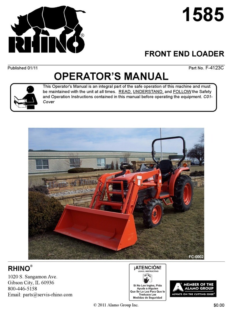
Kubota LA513 User manual

OPERATOR'S MANUAL
KUBOTA
FRONT LOADER
MODELS 1A513
LA723
LA853
READ AND SAVE THts MANUAL K,,l bOla

ABBREVIATION LIST
Abbreviations Definitions
2WD
4WD
API
ASAE
ASTM
DIN
DT
fpm
GST
Hi-Lo
HST
m/s
PTO
RH/LH
ROPS
rpm
r/s
SAE
SMV
UDT
Two Wheel Drive
Four Wheel Drive
American Petroleum I nstitute
American Society of Agricultural Engineers, USA
American Society for Testing and Materials, USA
Deutsches Institut fur Normung, GERMANY
Dual Traction [4WD]
Feet Per Minute
Glide Shift Transmission
High Speed-Low Speed
Hydrostatic Transmission
Meters Per Second
Power Take Off
Right-hand and left-hand sides are determined
by facing in the direction of forward travel
Rol l-Over Protective Structu re
Revolutions Per Minute
Revolutions Per Second
Society of Automotive Engineers, USA
Slow Moving Vehicle
KU BOTA U DT fl uid (Transmission-hydrau lic fl uid)

FOREWORD
You are now the proud owner of a KUBOTA Loader. This loader is a product of
KUBOTA quality engineering and manufacturing. lt is made of fine materials
and under a rigid quality control system. lt will give you long, satisfactory
service. To obtain the best use of your loader, please read this manual carefully.
It will help you become familiar with the operation of the loader and contains
many helpful hints about loader maintenance. lt is KUBOTA's policy to utilize as
quickly as possible every advance in our research. The immediate use of new
techniques in the manufacture of products may cause some small parts of this
manual to be outdated. KUBOTA distributors and dealers will have the most up-
to-date information. Please do not hesitate to consult with them.
A SAFETY FtRsT
This symbol, the industry's "Safety Alert Symbol", is used throughout this
manual and on labels on the machine itself to warn of the possibility of personal
injury. Read these instructions carefully. lt is essential that you read the
instructions and safety regulations before you attempt to assemble or use this
unit.
A
A
A
DANGER: Indicates an imminently hazardous situation which, if not
avoided, will result in death or serious injury.
WARNING : Indicates a potentially hazardous situation which, if not
avoided, could result in death or serious injury.
CAUTION: Indicates a potentially hazardous situation which, if not
avoided, may result in minor or moderate injury.
IMPORTANT : Indicates that equipment or property damage could result
if instructions are not followed.
NOTE :Gives helpful information.

CONTENTS
SAFE OPERAT|ON.......... ....... 1
SERV|C|NG OF LOADER ................. 1
SPECIFICATTONS ..............2
SUITABLE TRACTOR ............2
LOADER SPECTFTCATTONS ............2
BUCKET SPECIFICATIONS... .............3
DTMENSTONAL SPEC|F|CAT|ONS ............ ..........4
OPERATIONAL SPECIFICATIONS... .........5
LOADER TERMINOLOGY. .......7
PRE-OPERATTON CHECK ................... B
LUBRTCATTON ..........8
TRANSMTSSTON FLUTD .....................8
TREAD ..................... B
REAR BALLAST .............9
Liquid ballast in rear tires.......... ................9
T|RE |NFLAT|ON............. ......... 10
Inflation pressure ...................10
TEST OPERAT|ON.......... ............... 10
REMOVING AIR FROM HYDRAULIC SYSTEM ........ ......11
OPERATING THE LOADER. ..............12
FILLING THE BUCKET......... ........12
LIFT|NG THE LOAD ........ ........ 13
CARRYING THE LOAD ............ 13
DUMPING THE BUCKET .... .......14
LOWERING THE BUCKET ........14
OPERATIONG WITH FLOAT ............14
LOADING FROM A BANK ........ 15
PEELING AND SCRAPING ...... 16
LOADING LOW TRUCKS OR SPREADERS FROM A PILE...., .......... 16
BACKF|LL|NG......... ........17
HANDLING LARGE HEAVY OBJECTS .....,..... 18
VALVE LOCK...... .......... 18
Standard va1ve......... ........... .18
Remote va1ve......... ...............18
BUCKET LEVEL |ND|CATOR.............. ....... 19
ATTACHING IMPLEMENTS ............ 19
DETACHING IMPLEMENTS.... .....,20
ATTACHMENTS ............21
Quick bucket .......21
Bale spear ...........21
Pallet fork........... ...................21
ASSEMBLE PALLET FORK ...........22
MAINTENANCE. ....23

LUBRTCATTON ........23
RE-TIGHTENING OF HARDWARE ............24
DAILY CHECKS ......,......24
General torque specification ............,.. ......................25
REMOVING THE LOADER ....26
sToRlNG THE LOADER .... ...........28
REINSTALLING THE LOADER. ........2g

SAFE OPERATION 1
A sAFE oPERATToN
Most loader equipment accidents can be avoided by following simple safety precautions.
These safety precautions, if followed at all times, will help you operate your loader safely.
1. Read and understand both the tractor and the loader 20.When loader work has been completed, lower the
operator's manuals before using the loader. loader boom to the ground, stop the engine, remove
Lack of knowledge can lead to accidents. the key and lock the brakes before leaving the tractor
2. For your safety, ROPS with a seat belt is strongly seat.
recommended by KUBOTA in almost all applications. 21 .Do not remove loader from tractor without approved
lf your tractor has a foldable ROPS, fold it down only bucket attached.
when absolutely necessary and fold it up and lock it 22.Make sure the parked loader is on stands and on a
again as soon as possible. Do not wear the seat belt hard, level surface.
when the foldable ROPS is down or the fixed ROPS is 23. Operate the loader controls only when properly seated
removed. lf you have any questions consult your local at the controls.
KUBOTA Dealer. 24.Visually check for hydraulic leaks and broken, missing,
Always use seat belt when the tractor is equipped with or malfunctioning parts.
a ROPS. Never use the seat belt when the tractor is Make necessary repairs before operation.
not equipped with a ROPS . 25. Escaping hydraulic oil under pressure can have
3. Do not lift or carry anybody on the loader, bucket or sufficient force to penetrate the skin, causing serious
' attachment. personal injury. Do not use hands to search for
4. Never allow anyone to get under the loader bucket or suspected leaks. lf injured by escaping fluid, obtain
reach through the boom when the bucket is raised. medicaltreatment immediately.
5. Do not walk or work under a raised loader bucket or 26. Before disconnecting hydraulic lines, relieve all
attachment unless it is securely blocked and held in hydraulic pressure.
position. 27.Do not tamper with the relief valve setting. The relief
6. Do not use the loader as a Jack to support the tractor valve is pre-set at the factory. Changing the setting
for servicing and maintenance. can cause overloading of the loader and tractor which
Securely support tractor or any machine elements with may result in a serious personal injury.
stands or suitable blocking before working 28. Using loaders for handling large heavy objects, such
underneath. as large round or rectangular bales, logs and oil drums
For your safety, do not work under any hydraulically is not recommended.
supported devices. They can settle, suddenly leak 29. Handling large heavy objects can be extremely
down, or be accidently lowered. dangerous due to :
7. When operating on a slope, always operate up and o Danger of rolling the tractor over.
down the slope, never across the slope. o Danger of upending the tractor.
8. Operate the loader from the tractor seat only. o Danger of the object rolling or sliding down the
9. For tractor stability and operator's safety, rear ballast loader boom onto the operator.
must be added to the 3-point hitch and to the rear 30.|f you must perform this sort of work (item 29), protect
wheels. yourself by :
10.To increase stability adjust the rear wheels to the o Never lift the load higher than necessary to clear
widest setting that is suitable for your application. the ground.
11. Move and turn the tractor at low speeds. o Adding rear ballast to the tractor to compensate for
12.Carry loader boom at a low position during transport. the load.
(You should be able to see over the bucket.) . Never lift large object with equipment that may
13. Exercise extra caution when operating the loader with permit it to roll back onto the operator.
a raised bucket or attachment. . Moving slowly and carefully, avoiding rough
14.Avoid loose fill, rocks and holes. They can be terrain.
dangerous for loader operation or movement. 31.lt is the owner's responsibility to be certain anyone
15. Be extra careful when working on inclines. operating the loader read this manual first to be aware
16.Avoid overhead wires and obstacles when loader is of the safe way of operating the loader.
raised. Contacting electric lines can cause 32.Always wear safety goggles when servicing or
electrocution. repairing the machine.
lT.Allowfortheloaderlengthwhenmakingturns. 33.When servicing or replacing pins in cylinder ends,
lS.Gradually stop the loader boom when lowering or bucket, etc., always use a brass drift and hammer.
lifting. Failure to do so could result in injury from flying metal
19. Use caution when handling loose or shiftable loads. fragments.
SAFE OPERATION
34. Replace damaged or illegible safety labels. See
following page for required labels.
35. Do not modify, alter, or permit anyone else to modify
or alter the loader, any of its components, or any
loader function without first consulting a KUBOTA
Dealer.
36.Assemble, remove and reinstall the loader only as
directed in this manual. Failure to do this could result
in serious personal injury or death.
37.When operating another implement on a hillside, be
sure to remove the loader to reduce the risk of roll
over.
38. Never lift or pull any load from any point of the loader
with a chain, rope, or cable. Doing so could cause a
roll over or serious damage to the loader.
39.When a front loader is mounted on the tractor, enter
and exit the operator's seat only from left side of the
tractor.

3SAFE OPERATION
O Part No.7J246-5643-1 @ Part No.7J246-5641-1
@ Part No.7J246-5645-1
@ Part No.7J246-5644-2
(Both sides)
e part No.7J266-5649-1 'O, Part No.7J246-5642-1
1.
2.
3.
4.
Keep danger,warning and caution labels clean and free from obstructing material.
Clean danger, warnning and caution labels with soap and water, dry with a soft cloth.
Replace damaged or missing danger, warning and caution labels with new labels from your local KUBOTA Dealer.
lf a component with danger, warning and caution label (s) affixed is replaced with new part, make sure new label (s) is
(are) attached in the same location (s) as the replaced component.
Mount new danger, warning and caution labels by applying on a clean dry surface and pressing any bubbles to outside
eoge.
lAIABAFAPOOTA

SERVICING OF LOADER
SERVICING OF LOADER
Your dealer is interested in your new loader and has the
desire to help you get the most value from it. After reading
this manual thoroughly, you will find that you can do some
of the regular maintenance yourself.
However, when in need of parts or major service, oe sure
to see your KUBOTA Dealer.
For service, contact the KUBOTA Dealership from which
you purchased your loader or your local KUBOTA Dealer.
When in need of parts, be prepared to give your dealer the
loader serial number.
Locate the serial numbers now and record them in the
space provided.
KUBOTA LOADER
Date of Purchase
Name of Dealer
(To be filled in by purchaser)
(1)Serial number

SPECIFICATIONS
SPECIFICATIONS
SUITABLE TRACTOR
1A513:13'1 30,3430
14723:13 1 30,3430,3830
LAB53: 14330,4630,5030
LOADER SPECIFICATIONS
LOADER MODEL LA513 LA.723 1A853
TRACTOR MODEL 13130,3430 13130.3430.3830 14330,4630,5030
WHEEL BASE(WB) mm (in) 1 805
(71 .1) 1 805-1 840
(71.1-72.4) 1 895-1 91 5
(74.6-75.4)
FRONT TIRES 7.2-16 8.3-16 9.5-16
REAR TIRES 12.4-24 14.9-24 14.9-26
BOOM CYLINDER BORE mm (in) 45(1.77) 50(1.97) 60(2.36)
STROKE mm (in) 476(18.7) 502(1e.8) 496(19.5)
BUCKET CYLINDER BORE mm (in) 45(1.77) 50(1.e7) 55(2.17)
STROKE mm (in) 476(18.7) 465(18.3) 469(18.5)
CONTROL VALVE One Detent Foat Position, Power Beyond Circuit
RATED FLOW L/m (GPM) 31.5(8.3) 37(e.8)
MAXIMUM PRESSURT MPa (kg/cm',psi) 1 B5(2630)
NET WEIGHT(APPROXI MATE) ks (lbs.) 3eo(B6o) 480(1 058) 525(1157)

SPECIFICATIONS 3
BUCKET SPECIFICATIONS
LOADER MODEL 1A513 LA723 LA853
MODEL SQUARE 66" ROUND 66"
HD SQUARE
72 ROUND 72'
HD SQUARE
72" ROUND 72"
HD
TYPE RIGID RIGID RIGID RIGID RIGID RIGID
WIDTH mm (in.) 1675 (66) 18s0 (72)
DEPTH (L) mm (in.) 458 (18) 440 (17.3) 50e (20) 440 (17.3) 547 (21.5) 477 (18.8)
HETGHT (M) mm (in.) 562 (22.1) 580 (22.8) 562 (22.1) 580 (22.8) 570 (22.4) 608 (23.9)
LENGTH (N) mm (in.) 502 (19.8) s31 (20.9) 5el (23.3) 570 (22.4) 652 (25.7) 630 (24.8)
CAPACITY
STRUCK m'
(cu.FT.) 0.23 (8,1) 0.25 (8.8) 0.31 (10.e)
HEAPED m'
(cu.Fr.) 0.28 (e.e) 0.31 (10.9) 0.37 (13.1)
WEIGHT ks (lbs.) 112 (247) 122 (26s1 133 (293) 150 (331) 146(322) 1U (362')
LOADER MODEL LA513,LA723,LA853 LA723,LA853 LA513,LA723,LA853
MODEL SQUARE 66" ROUND 66"
HD SQUARE
72' ROUND 72"
HD SQUARE 72" LIGHT
MATERIAL
TYPE QUICK
ATTACH QUICK
ATTACH QUICK
ATTACH QUICK
ATTACH QUICKATTACH
WIDTH mm (in.) 1675 (66) 1$0 (72)
DEPTH (L) mm (in.) 458 (18) 440 (17.3) u7 (21.5) 477 (18.8) 607 (23.9)
HETGHT (M) mm (in.) 562 (22.1) 580 (22.8) 570 (22.4) 608 (23.e) 57O (22.4)
LENGTH (N) mm (in.) 544 (21.4) 57O (22.4) 630 (24.8) 610 (24) 6s1 (27.2)
CAPACITY
STRUCK m"
(cu.Fr.) 0.23 (8.1) 0.31 (10.9) 0.36 (12.7)
HEAPED m'
(cu.FT.) 0.28 (e.e) 0.37 (13.1) 0.45 (16.0)
WEIGHT kg (lbs.) 120 (265) 130 (287) 150 (331) 1 80 (397) 136 (300)

SPECIFICATIONS
DIMENSIONAL SPECIFICATIONS
LOADER MODEL LA513 L4723 LA853
TRACTOR MODEL 13130,3430 13130.3430.3830 14330.4630.5030
AMAX. L|FT HETGHT (TO BUCKET
PIVOT PIN) mm (in.) 2450 (96.5) 2600 (102.4) 2885 (1 13.6)
BMAX. LIFT HEIGHT UNDER LEVEL
BUCKET mm (in.) 2280 (8e.8) 2400 (94.5) 2685 (105.7)
CLEARANCE WITH BUCKET
DUMPED mm (in.) 1008 /74 6\ 2040 (80.3) 2280 (8e.8)
DREACH AT MAX. LIFT HEIGHT
(DUMPING REACH) mm (in.) 525 (20.7) I 530(20.9) 510 (20.1)
EMAX. DUMP ANGLE deg. 40
r
t- REACH WITH BUCKET ON GROUND mm (in.) 1570 (61 .8) 1750 (68.9) 1e05 (75)
\, BUCKET ROLL-BACK ANGLE deg. , 30 40
HDIGGING DEPTH mm (in )125 (4.s) 170 (6.7)
JOVERALL HEIGHT IN CARRYING
POSITION mm (in.) 1335 (52.6) 1385 (54.5) 1450 (57.1 )

SPECIFICATIONS
OPERATIONAL SPECIFICATIONS
LOADER MODEL LA513 LA.723 LA853
TRACTOR MODEL 13130,3430 131 30,3430,
3830 14330,4630,
5030
LIFT CAPACITY (BUCKET BOTTOM MID POINT) kg (lbs.) 510 (1124) 720 (1587) 850 (1874)
ULIFT CAPACITY (BUCKET PIVOT PIN, MAX. HEIGHT) ks (lbs.) 610 (1345) 848 (1870) 1077 (2374)
LIFT CAPACITY (500mm FORWARD, MAX. HEIGHT) ks (lbs.) 455 (1003) 635 (1400) 800 (1 764)
WllFT CAPACITY (BUCKET PIVOT PlN, 1500mm HEIGHT) kg (lbs.) 800 (1764) 1051 (2317) 1 345 (2965)
XLIFT CAPACITY (500mm FORWARD, 1500mm HEIGHT) kg (lbs.) 630 (1 38e) 840 (1852) 1086 (2394)
BREAKOUT FORCE (BUCKET PTVOT PtN) N (lbs.) 12640 (2845) 1 4995 (3375) 17840 (4015)
zBREAKOUT FORCE (500mm FORWARD) N (lbs.) 9600 (2160) 1 1 575 (2605) 1 3BB0 (31 25)
BUCKET ROLL-BACK FORCE AT MAX. HEIGHT N (lbs.) 1 0650 (2395) 1 0330 (2325) 1 091 0 (2455)
XX BUCKET ROLL-BACK FORCE AT 1.5M N (lbs.) 1 3780 (31 00) 1 5520 (3490) 18640 (41e0)
ZZ BUCKET ROLL-BACK FORCE AT GROUND LEVEL N (lbs.) 1 1 880 (2670) 1 6090 (3620) 19750 (4440)
RAISING TIME JUU. 2.7 J.J ^1
LOWERING TIME sec. 2.2 2.2 J. l
BUCKET DUMPING TIME sec 1.3 t.J LO
BUCKET ROLLBACK TIME sec 1.6 2.1 2.2
/\
-4-1T \uu
| 50omm I
r-------1
UV
_\o_/\"
q---// \i
-x__J
| 50omm I
{*-------1
WX

SPECIFICATIONS
At pivot pin
V
\\
.500 mn
\,'/ of pivot forward
rin
LAs13
3000
2500
2 2000
I
E
+, 1500
.v
f tooo
500
0
LA.723
{ 3000
2500
a 2000
i
!.,roo
.3
# tooo
500
0
LA853
3000
2500
2 2000
)
!,uoo
.v
€ tooo
500
0
2000
2000
3000
2500
a 2000
E
E
g 1500
.s
q)
r 1000
500
0
3000
2500
a 2000
E
€
g 1500
.!9
o
r 1000
500
0
500 1000 1500
Lift Capacity (re)
1000 1500
Lift Capacity (kc)
1000 1500
Lift Capacitv (kg)
10 't5 20
Rol lback Force (KN)
15 20
Rol lbaok Force (KN)
25
500 2510
3000
2500
a 2000
E
s
g 1500
.9
o
r 1000
500
0t5
Rol lback 20
Force (KN)
,At pivot pin
/ \\
500 mm forwi
of pivot pin .\\
\lt oivot oir
\
\\
\\
500 mn
of pivot forward \
pin \
500 2000 l0 25

SPECIFICATIONS 7
LOADER TERMINOLOGY
(1)Hydraulic control valve (6)Boom
(2)Side frame (7)Bucket cylinder
(3)Mounting pin (B)Bucket
(4)Main frame
(5)Boom cylinder

PRE.OPERATION CHECK
LUBRICATION TRANSMISSION FLUID
Lubricate all grease fittings with SAE multipurpose Check tractor transmission fluid level. Add fluid if
necessary. Rerer to the tractor operator's manual for
instructrons a.c oroper fluid. Repeat this check after
purging air fi-o- the system. At that time, it will be
necessary to acc :rarsmission fluid.
IMPORTANT r
r To cl'ec< :'ac:or" :'arsmission fluid level, lower the
bucket i: :^e f,.c-.I a^c ;o\.,'er the 3 point hitch.
TREAD
i , Set froni tread as follows.
PRE-OPERATION CHECK
lLA723,LA853j IMPORTANT:
o Setting tread wider than recommended may cause
premature failure of front axle components due to
excessive stress.
2. For better stability, set the rear tread as follows
depending on the requirements of the work being
done.
Rear Tread
131 30
13430 1200mm A7.2in.\ or more
13830
14330
14630 1285mm (50.6 in.) or more
15030 1325mm (52.2in.\ or more

PRE-OPERATION CHECK
REAR BALLAST
CAUTION
To avoid personal injury:
o For tractor stability and operator's safety, rear
ballast should be added to the rear of the tractor in
the form of 3-point counter weight and rear wheel
ballast. The amount of rear baltast will depend on
the application.
lmplement as Counter Weight
6'Box Scraper Approx. 450 kg (990 lbs.)
Rotary Tiller Approx. 240 kg (530 lbs.)
Back Hoe Approx. 770 kg (1690 lbs.)
ILiquid ballast in reartires
Water and calcium chloride solution provides a safe and
economical ballast. Used properly, it will not damage tires,
tubes or rims. The addition of calcium chloride is
recommended to prevent the water from freezing. Use of
this method of weighting the wheels has full approval o{
the tire manufacturers. See Vour tire dealer for this
service.
Liquid weight per tire (75 Percent filled)
IMPORTANT:
. Do not fill tires with water or solution more than 75% ot
full capacity (to the valve stem level at 12 o'clock
position).
a Do not fill tires with water or solution if the tractor is a
CAB model.
(1)Air
(2)Water
(A)Correct: 75% Full
Air compresses like a cushion
(B) lncorrect: 1 00% F ull
Water can not be compressed
NOTE:
. When mounting a heavy rear implement, liquid in the
tires may not be required.
IMPORTANT:
. Do not add liquid ballast or any other weights to the
front tires.
Tire sizes 12.4-24 424t70-24 14.9-24
Slush free at -1 0 I (1 a "f )
Solid at -30'C (-22"F )
lApprox. 1 kg (2 lbs.)
CaCl, per4 L (1 gal.)of waterl
'130 kg
(285 lbs.) 195 kg
(430 lbs.) 205 kg
(450 lbs.)
Slush free at -24'C (-1 1 'F )
Solid at -47 C (-52'F )
lApprox. 1.5 kg (3.5 lbs.)
CaCl, per 4 L (1 gal.)of waterl
135 kg
(295 lbs.) 205 kg
(450 lbs.) 215 kg
(475 lbs.)
Slush free at -47'C (-52"F )
Solid at -s2 C (-62'F )
lApprox. 2.25 kg (5 lbs.)
CaCl, per4 L (1 gal.)of waierl
145 kg
(320 lbs.) 220 kg
(485 lbs.) 225 kg
(495 lbs.)
Tire sizes 17.5L-24 14.9-26 13.6-28
Slush free at - 1 0 "C (1a "f )
Solid at -30 "C (-22"F )
lApprox. 1 kg (2 lbs )
CaCl, per 4 L (1 gal.) of waterl
235 kg
(515lbs.) 215 kg
(475 lbs.) 185 kg
(405 lbs.)
Slush free at -24'C (-i 1 'F )
Solid at -47 C (-s2 "F )
lApprox. 1.5 kg (3 5 lbs )
CaCl, per4 L (1 gal.)of waterl
250 kg
(550 lbs.) 225 kg
(495 lbs.) 200 kg
(441 lbs.)
Slush free aI -47'C l.52'7 i
Solid at -52 'C (-62 "F )
lApprox. 2.25 kg (5 lbs.)
CaCl, per4 L (1 gal.)of waterl
265 kg
(585 lbs.) 23s kg
(515 lbs.) 215 kg
(475 lbs.)

10 PRE-OPERATION CHECK
TIRE INFLATION
Insure that the tractor tires are properly inflated.
Refer to the tractor operator's manual for optional tires.
llnflation pressure
TEST OPERATION
6 CAUTION
To avoid serious personal injury:
. Keep engine speed at low idle during the test
operation.
a Escaping hydraulic fluid under pressure can
have sufficient force to penetrate skin, causing
serious personal injury.
Before disconnecting lines, be sure to relieve
all pressure.
Before applying pressure to system, be sure all
connections are tight and that lines, tubes and
hoses are not damaged.
Fluid escaping from a very small hole can be
almost invisible, Use a piece of cardboard or
wood, rather than your hands to search for
suspected leaks.
lf injured by escaping fluid, see a doctor at
once. Serious infection or allergic reaction will
develop if proper medical treatment is not
administered immediately.
NOTE:
o When the lever is at each corner position marked by
asterisk (-), boom and bucket cylinders work at the
same time. However, the position marked is not
recommended for scooping because of insufficient lift
force.
To begin test operation, slightly move the control lever
from the "N" position. Slowly raise the loader boom just
enough for the bucket to clear the ground when fully
dumped. Slowly work through the dump and roll back
cycles.
IMPORTANT:
o lf the boom or bucket does not work in the directions
indicated on the label, lower the bucket to the ground,
stop the engine, and relieve all hydraulic pressure.
Recheck and correct all hvdraulic connections.
@
@
G
@
.i.
w
+8a
*\
5
N
N
Tire sizes Inflation Pressure
Rear
12.4-24,4PR 140 kPa (1.4 kgf/cm .20 ps I
13.6-28, 4PR 150 kPa (1.5 kgficm . 22 ps 1
14.9-24,4PR 140 kPa (1.4 kgf/cm'. 20 cs
14.9-26, 4PR 140 kPa (1 4 kgf'cm 2C cs
41l18LL x 16.1,6PR 70 kPa (0.7 kgf:cm . 1O csl '
355/80-D20 4PR 100 kPa (1 .0 kgf cm', 14 psr;
44 x 18-20, 6PR 170 kPa (1.7 kgilcm',24 psi)
420t70-24,6PR 140 kPa (1.4 kgf/cm', 20 psi)
17.51-24,6PR 140 kPa (1.4 kgf/cm'. 20 psi)
Front
6.00-16,4PR 220 kPa (2.2 kgf/cm', 32 psi)
7.2-16, 4PR 150 kPa (1.5 kgf/cm', 22 psi)
8.3-16,4PR 150 kPa (1.5 kgf/cm', 22 psi)
9.5-16,4PR 205 kPa (2.1 kgf/cm', 30 psi)
27 x 8.50-15, 4PR 85 kPa (8.5 kgf/cm', 12 psi)
27 x 10.50-15,4PR 85 kPa (8.5 kgf/cm', 12 psi)
29 x 12.50-15,4PR 140 kPa (1.4 kgf/cm', 20 psi)
10-16.5.6PR 140 kPa ('1 .4 kgf/cm', 20 psi)
7.51-15, 6PR 220 kPa (2.2 kgflcm' ,32 psi)

PRE-OPERATION CHECK 11
REMOVING AIR FROM HYDRAULIC
SYSTEM
Repeat raising and lowering the boom and bucket
operations until all the air is removed from the system and
the system responds properly.
IMPORTANT:
. Do not move the control lever into float position when
the bucket is off the oround.

OPERATING THE LOADER
12 OPERATING THE LOADER
The loader should be operated with the tractor engine
speed depending on the application and the operator's
level of experience. Excessive speeds are dangerous,
and may cause bucket spillage and unnecessary strain on
the tractor and loader.
When operating in temperatures below -'1 'C (30 "F ), run
the tractor engine below 1200 rpm until the oil
temperature exceeds -1 'C (30'f ).
The following text and illustrations offer suggested loader
and tractor operating techniques.
A CAUTION
To reduce the possibility of roll over:
a lt is not recommended that the loader be
attached when operating another implement on
, ^ hillside.
IMPORTANT:
t When operating the loader in rough terrain,
remove the mower to avoid damage to the mower.
FILLING THE BUCKET
Approach and enter the pile with a level bucket
Ease control lever toward you and then back to rollback
and lift the bucket.
The rollback and lifting of the bucket will increase
efficiency because a level bucket throughout the lifting
cycle resists bucket lift and increases breakaway effort.
NOTE:
. Do not be concerned if the bucket is not completely
filled during each pass. Maximum productivity is
determined by the amount of material loaded in a
given period of time. Time is lost if two or more
attempts are made to fill the bucket on each pass.
This manual suits for next models
2
Table of contents
Other Kubota Front End Loader manuals

Kubota
Kubota LA213 User manual

Kubota
Kubota R540 User manual

Kubota
Kubota LA525 Instruction manual

Kubota
Kubota LA1353 Instruction manual

Kubota
Kubota WSM LA1403 User manual

Kubota
Kubota LA434 User manual

Kubota
Kubota BX2370 Instruction manual

Kubota
Kubota LA535 User manual

Kubota
Kubota LA1954 User manual

Kubota
Kubota LA344 Instruction manual