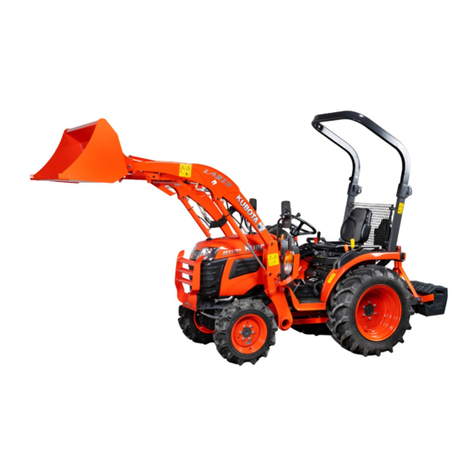
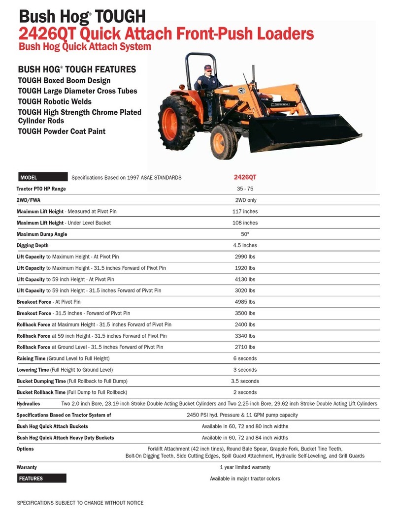
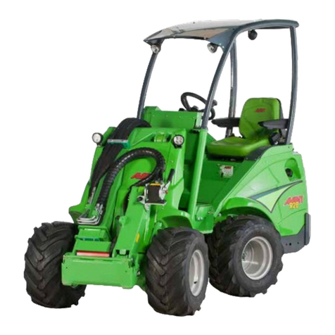
Kubota LA525 Instruction manual

LA525,LA765
WORKSHOP MANUAL
FRONT LOADER
KiSC issued 06, 2017 A

TO THE READER
This Workshop Manual tells the servicing personnel about the mechanism, servicing and
maintenance of the Front Loader LA525 and LA765. It contains 4 parts: "Information", "General",
"Mechanism" and "Servicing".
Information
This section primarily contains information below.
• Safety First
• Safety Decal
• Terminology
• Specification
General
This section primarily contains information below.
• Loader Identification
• General Precautions
•Lubricants
• Tightening Torques
• Maintenance Check List
• Check and Maintenance
Mechanism
This section contains information on the structure and the function of the unit. Before you continue
with the subsequent sections, make sure that you read this section.
Servicing
This section primarily contains information below.
• Troubleshooting
• Servicing Specifications
• Tightening Torques
• Removing Front Loader from Tractor
• Checking, Disassembling and Servicing
All illustrations, photographs and specifications contained in this manual are of the newest
information available at the time of publication.
KUBOTA reserves the right to change all information at any time without notice.
Since this manual includes many models, information or illustrations and photographs can show
more than one model.
February, 2014
© KUBOTA Corporation 2014
KiSC issued 06, 2017 A

Record of Revisions
For pdf, use search function {Search word} to find all the revised locations.
Last digit
of the
Code No.
Issue
month Main Revised Point and Corrective Measures {Search word} Reference
Page
12014.08 Add new adaptable tractor {L2501} I-9
22017.06 Revised the contents of safety decals I-7
KiSC issued 06, 2017 A

I INFORMATION
KiSC issued 06, 2017 A

CONTENTS
1. SAFETY FIRST .............................................................................................................................. I-1
2. SAFETY DECALS .......................................................................................................................... I-4
3. LOADER TERMINOLOGY ............................................................................................................. I-8
4. SPECIFICATIONS.......................................................................................................................... I-9
[1] LOADER SPECIFICATIONS.................................................................................................... I-9
[2] BUCKET SPECIFICATIONS .................................................................................................... I-9
[3] DIMENSIONAL SPECIFICATIONS........................................................................................ I-10
(1) LA525 ............................................................................................................................... I-10
(2) LA765 ............................................................................................................................... I-11
[4] OPERATIONAL SPECIFICATIONS ....................................................................................... I-12
(1) Specifications Table .........................................................................................................I-12
(2) Performance Curves......................................................................................................... I-14
INFORMATION
KiSC issued 06, 2017 A

INFORMATION
LA525, LA765, WSM
I-1
1. SAFETY FIRST
WSM000001INI0001US1
BEFORE YOU START SERVICE
• Read all instructions and safety instructions in this
manual and on your machine safety decals.
• Clean the work area and machine.
• Park the machine on a stable and level ground, and
set the parking brake.
• Lower the implement to the ground.
• Stop the engine, then remove the key.
• Disconnect the battery negative cable.
• Hang a "DO NOT OPERATE" tag in the operator
station.
WSM000001INI0010US0
START SAFELY
• Do not do the procedures below when you start the
engine.
– short across starter terminals
– bypass the safety start switch
• Do not alter or remove any part of machine safety
system.
• Before you start the engine, make sure that all shift
levers are in neutral positions or in disengaged
positions.
• Do not start the engine when you stay on the ground.
Start the engine only from operator's seat.
WSM000001INI0015US0
SAFETY FIRST
• This symbol, the industry's "Safety Alert Symbol", is used throughout this manual and on labels on the
machine itself to warn of the possibility of personal injury. Read these instructions carefully.
• It is essential that you read the instructions and safety regulations before you try to repair or use this
unit.
DANGER
• Indicates an imminently hazardous situation which, if not avoided, will result in death or serious injury.
WARNING
• Indicates a potentially hazardous situation which, if not avoided, could result in death or serious injury.
CAUTION
• Indicates a potentially hazardous situation which, if not avoided, could result in minor or moderate
injury.
IMPORTANT
• Indicates that equipment or property damage could result if instructions are not followed.
NOTE
• Gives helpful information.
KiSC issued 06, 2017 A

INFORMATION
LA525, LA765, WSM
I-2
OPERATE SAFELY
• Do not use the machine after you consume alcohol
or medication or when you are tired.
• Put on applicable clothing and safety equipment.
• Use applicable tools only. Do not use alternative
tools or parts.
• When 2 or more persons do servicing, make sure
that you do it safely.
• Do not operate below the machine that only a jack
holds. Always use a safety stand to hold the
machine.
• Do not touch the hot parts or parts that turn when the
engine operates.
• Do not remove the radiator cap when the engine
operates, or immediately after it stops. If not, hot
water can spout out from the radiator. Only remove
the radiator cap when it is at a sufficiently low
temperature to touch with bare hands. Slowly loosen
the cap to release the pressure before you remove it
fully.
• Released fluid (fuel or hydraulic oil) under pressure
can cause damage to the skin and cause serious
injury. Release the pressure before you disconnect
hydraulic or fuel lines. Tighten all connections before
you apply the pressure.
• Do not open a fuel system under high pressure.
The fluid under high pressure that stays in fuel lines
can cause serious injury. Do not disconnect or repair
the fuel lines, sensors, or any other components
between the fuel pump and injectors on engines with
a common rail fuel system under high pressure.
• Put on an applicable ear protective device (earmuffs
or earplugs) to prevent injury against loud noises.
• Be careful about electric shock. The engine
generates a high voltage of more than DC100 V in
the ECU and is applied to the injector.
WSM000001INI0012US0
PREVENT A FIRE
• Fuel is very flammable and explosive under some
conditions. Do not smoke or let flames or sparks in
your work area.
• To prevent sparks from an accidental short circuit,
always disconnect the battery negative cable first
and connect it last.
• The battery gas can cause an explosion. Keep the
sparks and open flame away from the top of battery,
especially when you charge the battery.
• Make sure that you do not spill fuel on the engine.
WSM000001INI0005US0
KiSC issued 06, 2017 A

INFORMATION
LA525, LA765, WSM
I-3
KEEP A GOOD AIRFLOW IN THE WORK AREA
• If the engine is in operation, make sure that the area
has good airflow. Do not operate the engine in a
closed area. The exhaust gas contains poisonous
carbon monoxide.
WSM000001INI0006US0
DISCARD FLUIDS CORRECTLY
• Do not discard fluids on the ground, down the drain,
into a stream, pond, or lake. Obey related
environmental protection regulations when you
discard oil, fuel, coolant, electrolyte and other
dangerous waste.
WSM000001INI0007US0
PREVENT ACID BURNS
• Keep electrolyte away from your eyes, hands and
clothing. Sulfuric acid in battery electrolyte is
poisonous and it can burn your skin and clothing and
cause blindness. If you spill electrolyte on yourself,
clean yourself with water, and get medical aid
immediately.
WSM000001INI0008US0
PREPARE FOR EMERGENCIES
• Keep a first aid kit and fire extinguisher ready at all
times.
• Keep the emergency contact telephone numbers
near your telephone at all times.
WSM000001INI0009US0
KiSC issued 06, 2017 A

INFORMATION
LA525, LA765, WSM
I-4
2. SAFETY DECALS
The following safety decals are installed on the machine. If a decal becomes damaged, illegible or is not
on the machine, replace it. The decal part number is listed in the parts list.
WSM000001INI0013US0
9Y1211014INI0015US0
KiSC issued 06, 2017 A

INFORMATION
LA525, LA765, WSM
I-5
9Y1211014INI0001US0
KiSC issued 06, 2017 A

INFORMATION
LA525, LA765, WSM
I-6
9Y1211014INI0002US0
KiSC issued 06, 2017 A

INFORMATION
LA525, LA765, WSM
I-7
9Y1211014INI0003US0
CARE OF DANGER, WARNING AND CAUTION LABELS
1. Keep danger, warning and caution labels clean and free from obstructing material.
2. Clean danger, warning and caution labels with soap and water, dry with a soft cloth.
3. Replace damaged or missing danger, warning and caution labels with new labels from your local KUBOTA dealer.
4. If a component with danger, warning and caution label(s) affixed is replaced with new part, make sure new label(s)
is (are) attached in the same location(s) as the replaced component.
5. Attach new danger, warning and caution labels on a clean dry surface. Push any bubbles to outside edge.
9Y1211014INI0004US0
KiSC issued 06, 2017 A

INFORMATION
LA525, LA765, WSM
I-8
3. LOADER TERMINOLOGY
9Y1211014INI0005US0
(1) Loader Control Lever
(2) Side Frame
(3) Mounting Pin
(4) Main Frame
(5) Boom Cylinder
(6) Boom
(7) Bucket Cylinder
(8) Bucket
KiSC issued 06, 2017 A

INFORMATION
LA525, LA765, WSM
I-9
4. SPECIFICATIONS
Suitable Tractor
9Y1211014INI0006US0
[1] LOADER SPECIFICATIONS
9Y1211014INI0007US0
[2] BUCKET SPECIFICATIONS
9Y1211014INI0008US0
Loader Model LA525 LA765
Tractor Model L2501, L3301, L3901 L4701
Loader Model LA525 LA765
Tractor Model L2501 L3301, L3901 L4701
Model 2WD 4WD 2WD 4WD 2WD 4WD
Wheel Base (WB) 1610 mm (63.3 in.) 1850 mm
(72.8 in.) 1845 mm (72.6 in.)
Front Tires 7 - 16 7.5L-15 8.3-16
Rear Tires 11.2-24 14.9-24
Boom Cylinder Bore 45 mm (1.77 in.) 50 mm (1.97 in.)
Stroke 476 mm (18.7 in.) 520 mm (20.5 in.)
Bucket Cylinder Bore 45 mm (1.77 in.) 50 mm (1.97 in.)
Stroke 476 mm (18.7 in.) 480.5 mm (18.9 in.)
Control Valve 3 position bucket
control type
One Detent Float Position, Regenerative Bucket Dump,
Power Beyond Circuit
Rated Flow 23.9 /min. (6.3 GPM) 29.4 /min. (7.8 GPM)
Maximum Pressure
15.7 MPa
160 kgf/cm2
2275 psi
16.2 MPa
165 kgf/cm2
2347 psi
17.7 MPa
180 kgf/cm2
2560 psi
Net Weight (Approximate) 365 kg (805 lbs) 524 kg (1155 lbs)
Loader Model LA525 LA765
Model SQUARE 60" SQUARE 66" SQUARE 72" ROUND 72" HD SQUARE 72"
LIGHT MATERIAL
Type Rigid Quick Attach Quick Attach Quick Attach Quick Attach
Width 1525 mm (60 in.) 1675 mm (66 in.) 1830 mm (72 in.)
Depth "L" 463 mm (18.2 in.) 458 mm (18 in.) 547 mm (21.5 in.) 477 mm (18.8 in.) 607 mm (23.9 in.)
Height "M" 559 mm (22 in.) 562 mm (22.1 in.) 570 mm (22.4 in.) 608 mm (23.9 in.) 570 mm (22.4 in.)
Length "N" 511 mm (20.1 in.) 544 mm (21.4 in.) 630 mm (24.8 in.) 610 mm (24 in.) 691 mm (27.2 in.)
Capacity
Struck 0.22 m3
(7.8 cu.ft.)
0.23 m3
(8.1 cu.ft.) 0.31 m3(10.9 cu.ft.) 0.36 m3
(12.7 cu.ft.)
Heaped 0.26 m3
(9.2 cu.ft.)
0.28 m3
(9.9 cu.ft.) 0.37 m3(13.1 cu.ft.) 0.45 m3
(16.0 cu.ft.)
Weight 82 kg (181 lbs) 120 kg (265 lbs) 150 kg (331 lbs) 180 kg (397 lbs) 136 kg (300 lbs)
KiSC issued 06, 2017 A

INFORMATION
LA525, LA765, WSM
I-10
[3] DIMENSIONAL SPECIFICATIONS
(1) LA525
9Y1211014INI0009US0
Loader Model LA525
Tractor Model L2501, L3301, L3901
Bucket Type Rigid
AMaximum lift height (To bucket pivot pin) 2394 mm
(94.3 in.)
BMaximum lift height under level bucket 2224 mm
(87.6 in.)
CClearance with bucket dumped 1936 mm
(76.2 in.)
DReach at maximum lift height
(Dumping Reach)
645 mm
(25.4 in.)
EMaximum dump angle 0.70 rad (40 °)
FReach with bucket on ground 1618 mm (63.7 in.)
GBucket roll-back angle 0.54 rad (31 °)
HDigging depth 176 mm (6.9 in.)
JOverall height in carry position 1302 mm (51.3 in.)
aLength 500 mm (19.7 in.)
KiSC issued 06, 2017 A

INFORMATION
LA525, LA765, WSM
I-11
(2) LA765
9Y1211014INI0010US0
Loader Model LA765
Tractor Model L4701
AMaximum lift height (To bucket pivot pin) 2673 mm (105.2 in.)
BMaximum lift height under level bucket 2431 mm (95.7 in.)
CClearance with bucket dumped 2063 mm (81.2 in.)
DReach at maximum lift height
(Dumping Reach) 537 mm (21.1 in.)
EMaximum dump angle 0.72 rad (41 °)
FReach with bucket on ground 1783 mm (70.2 in.)
GBucket roll-back angle 0.47 rad (27 °)
HDigging depth 156 mm (6.1 in.)
JOverall height in carrying position 1387 mm (54.6 in.)
aLength 500 mm (19.7 in.)
KiSC issued 06, 2017 A

INFORMATION
LA525, LA765, WSM
I-12
[4] OPERATIONAL SPECIFICATIONS
(1) Specifications Table
[A] LA525
9Y1211014INI0011US0
Loader Model LA525
Tractor Model L2501 L3301, L3901
Bucket Type Rigid
ULift capacity (Bucket pivot pin, max. height) 491 kg (1082 lbs) 513 kg (1131 lbs)
VLift capacity (500 mm forward, max. height) 372 kg (820 lbs) 388 kg (855 lbs)
WLift capacity
(Bucket pivot pin, 1500 mm height) 649 kg (1431 lbs) 676 kg (1490 lbs)
XLift capacity
(500 mm forward, 1500 mm height) 515 kg (1135 lbs) 536 kg (1182 lbs)
YBreakout force (Bucket pivot pin) 10554 N (2373 lbf) 10951 N (2462 lbf)
ZBreakout force (500 mm forward) 8033 N (1806 lbf) 8335 N (1874 lbf)
VV Bucket roll-back force at maximum height 9403 N (2114 lbf) 9685 N (2177 lbf)
XX Bucket roll-back force at 1500 mm 11646 N (2618 lbf) 11998 N (2697 lbf)
ZZ Bucket roll-back force at ground level 9545 N (2146 lbf) 9855 N (2215 lbf)
Raising time (Rated flow) 4.1 sec. 3.5 sec.
Lowering time (Rated flow) 2.4 sec. 2.3 sec.
Bucket dumping time (Rated flow) 2.0 sec. 1.7 sec.
Bucket roll-back time (Rated flow) 2.6 sec. 2.2 sec.
KiSC issued 06, 2017 A

INFORMATION
LA525, LA765, WSM
I-13
[B] LA765
9Y1211014INI0012US0
Loader Model LA765
Tractor Model L4701
ULift capacity (Bucket pivot pin, max. height) 764 kg (1684 lbs)
VLift capacity (500 mm forward, max. height) 573 kg (1263 lbs)
WLift capacity
(Bucket pivot pin, 1500 mm height) 977 kg (2154 lbs)
XLift capacity
(500 mm forward, 1500 mm height) 783 kg (1726 lbs)
YBreakout force (Bucket pivot pin) 14023 N (3153 lbf)
ZBreakout force (500 mm forward) 10865 N (2443 lbf)
VV Bucket roll-back force at maximum height 12763 N (2869 lbf)
XX Bucket roll-back force at 1500 mm 16429 N (3673 lbf)
ZZ Bucket roll-back force at ground level 13345 N (3000 lbf)
Lifting time (Rated flow) 4.0 sec.
Lowering time (Rated flow) 2.5 sec.
Bucket dumping time (Rated flow) 1.6 sec.
Bucket roll-back time (Rated flow) 2.5 sec.
KiSC issued 06, 2017 A

INFORMATION
LA525, LA765, WSM
I-14
(2) Performance Curves
[A] LA525
9Y1211014INI0014US0
[B] LA765
9Y1211014INI0013US0
(1) At Pivot Pin
(2) 500 mm Forward of Pivot Pin
(a) Height (mm) (b) Lift Capacity (kg) (c) Rollback Force (kN)
(1) At Pivot Pin
(2) 500 mm Forward of Pivot Pin
(a) Height (mm) (b) Lift Capacity (kg) (c) Rollback Force (kN)
KiSC issued 06, 2017 A

G GENERAL
KiSC issued 06, 2017 A
Other manuals for LA525
1
This manual suits for next models
1
Table of contents
Other Kubota Front End Loader manuals

Kubota
Kubota LA213 User manual

Kubota
Kubota R540 User manual

Kubota
Kubota BX2370 Instruction manual

Kubota
Kubota LA534 User manual

Kubota
Kubota LA535 User manual

Kubota
Kubota LA344 Instruction manual

Kubota
Kubota LA1954 User manual

Kubota
Kubota LA513 User manual

Kubota
Kubota LA434 User manual

Kubota
Kubota WSM LA1403 User manual