KUDOS BI-SLIDER User manual

KUDOS
REFRESHING INNOVATION IN SHOWERS
BI-SLIDER
Installation Instructions
Please read these instructions before installing, as incorrect fitting will invalidate the guarantee.
Carry out each stage before moving onto the next. Do not dispose of packaging, no claims for
damaged or missing parts will be accepted if the packaging has been disposed of.
If you are unsure about these instructions please contact Kudos Shower Products:
Customer Service Helpline: 01539 564040
ORIGINAL RANGE
TOOLS REQUIRED KEY STAGES
IMPORTANT
GENERAL - for the frame work and fixings use only warm soapy water and damp cloth/ sponge on a regular basis. After cleaning
please rinse with clean water to remove any residue.
Do not use abrasive scouring powders, chemicals or aerosol cleaners - these may result in damage to the surfaces, in particular, the
plated component parts. See instruction below for glass cleaning advice.
CLEANING
LIFESHIELD
SILICONE
SEALANT
Check appearance of shower enclosure - any defects must be
reported to Kudos Shower Products before assembly/installation
Claims for imperfections will only be accepted prior to
assembly/installation.
Ensure the top of shower tray is level in all directions
Any claims made under the terms of the Lifetime Guarantee
must be reported to Kudos within 21 days of the fault occurring
Check the enclosure adjustment sizes are suitable for your
installation
Prior to tiling any, gap or crevice between the rim of the tray and
the wall must be filled with silicone sealant flush with the rim of the
tray - see Fig.1
Waterproof the walls using ceramic tiles/shower panels etc. before
installation of the shower enclosure
Fully seal between tiles/shower panels and the tray BEFORE
installing the enclosure - see Fig.2
Use care when drilling into the walls to avoid hidden pipes or
electric cables
FIG.1 FIG.2
Once the tray is installed but
before the tiles are fitted any
crevice between the tray and
the walls must be filled with
silicone sealant flush with the
top of the tray.
Once the walls have been
tiled but before the
enclosure is installed, the
tiles must be silicone sealed
to the tray all of the way
around in one continuous
bead.
Your Kudos Product is pre-treated with Life Shield on the inside surfaces only. While this makes cleaning the glass a lot easier and
helps prevent the build up of harmful lime-scale and soap deposits the glass still needs to be maintained on a regular basis. We
recommend the use of a detergent and aroma free glass cleaner (A 50/50 mix of Vinegar and Water works well!!) Strong detergents
and abrasives can damage the coating.
DO NOT use abrasive cleaners or abrasive scrubbing equipment for cleaning!!
DO use a squeegee to remove remaining droplets of water from glass after showering, any build up of residue can be removed easily
using an appropriate cleaner and agitation from soft cleaning equipment
THESE INSTRUCTIONS TO BE LEFT WITH THE CUSTOMER
?Remove sliding door glass
?Remove the clip-in extrusions
?Position and level the frame work in situ
?Drill walls and fix frame work
?Fit the sliding door
?Check & Adjust sliding door
?Silicone seal the enclosure
?Flat-Headed Screwdriver
?Pozi-Drive Screwdriver
?Spirit Level
?Tape Measure
?Silicone Sealant
?4mm & 2.5mm Allen Key (Supplied)
?Electric Drill
?7mm Drill Bit (Masonry)

If you are installing a side panel together with this door, please read these
instructions in conjunction with the instructions for the side panel provided
in the side panel packing.
IMPORTANT
Turn the door over on the protective surface, with the inside face of the door facing upwards.
Insert height adjusters into bottom of compensating channel / wall frames at bottom
of door as shown in fig. 2.1, 2.2 & 2.3. First insert spiral cam as shown in fig.2.1 into
both lower sides of frame, next slide height adjuster into both sides of frame and over
spiral cam fig.2.2 ensure height adjuster "clicks" into spiral cam as it engages and is
fully inserted fig. 2.3
2.1 2.3
2.2
INSERT SPIRAL CAM
INTO HOLE HERE
ORIENTATE CAM AS SHOWN
SLIDE HEIGHT ADJUSTER INTO FRAME
AND OVER SPIRAL CAM - IT CLICKS TO
ENGAGE. PUSH HEIGHT ADJUSTER FULLY
INTO FRAME - FLUSH WITH THE
BOTTOM OF THE DOOR
1
2Remove the sliding door glass from the unit. To do this first un clip the patch fittings
from the bottom rail. Then undo the allen key screw securing the top wheeled units to
the glass using the 4mm Allen key provided. Once the Allen screws are removed
carefully lift the glass up and away from the frame, taking care not to knock any
exposed edges. Do not stand directly onto a tiled floor, we recommend the use of a
towel to stand the glass onto. Remove the wheeled units from the top rail by lifting out
and keep safe.
Remove the screws that secure the four patch fittings of the fixed panel to the door rails, at
the top and bottom of the door. Fig. 3.1. Slide the fixed panel towards the centre of the frame
away from the wall post - ensure the rigid gasket on the edge of the glass remains securely
clipped onto the glass edge. Fig. 3.2
3.1 3.2
PUSH FIRMLY ON PATCH
FITTINGS TO MOVE PANEL
SLIDE OUT
3
Using 2.5mm allen key, loosen grub
screws in stop blocks in the top and
bottom rails and move towards
the fixed panel wall post.
BEFORE CARRYING OUT THESE INSTALLATION INSTRUCTIONS PLEASE DECIDE THE HANDING
OF THE DOOR, IF YOU NEED TO CHANGE THE HANDING READ THROUGH THE SUPPLEMENTARY
INSTRUCTIONS FIRST

4Remove the clip in extrusion from the inside face of door frame on handle side by pressing
down along entire length as shown in Fig. 4.1 then lifting away and out as shown in Fig. 4.2
Remove the clip in extrusion from the inside face of door frame on fixed panel side by lifting
up along entire length as shown in Fig. 5.1 then lifting away and out as shown in Fig. 5.2
5
4.2
4.1
PRESS DOWN ALONG
LENGTH TO RELEASE
5.1 5.2
6
7
Trim the excess lengths off wall post bubble seals (x4) Carefully offer frame into opening and
expand door width equally on both sides by turning the nylon adjustment screws - 3 at each
side of the door - in an anti-clockwise direction. Only tighten until door is lightly wedged in
position. Fig. 6.1
Set door level on tray by turning relevant height adjuster screw (clockwise to raise) if necessary.
Use a spirit level to ensure accurate levelling. Fig. 7.1 and 7.2
TO RAISE
TO EXPAND
6.1 7.1 7.2
Insert wall plugs provided or fixings to suit the construction of your walls (below tiles to avoid cracking) Fig.9.1
and offer door into position. Check the door frame is level, vertical and square on all sides of the opening,
checking to ensure the door is not leaning forward or backwards in the opening. Fig. 9.2. Frame MUST NOT
be twisted or buckled when fitting. Adjust the door ensuring frame is vertical using the adjustment screws as
per stage 6.and GENTLY tighten frame into opening ensuring sides of door frame are not distorted by
over-tightening. Fix door using 6 x No.8 Panhead 60mm screws provided. The middle screws may now be
adjusted to assist in plumbing the door frame. Be sure not to over tighten the middle screws
(finger tighten only) as this may cause "bowing" of the wall posts.
9
8.2
8.1
9.1 9.2
8Mark holes through wall frame of door - 3 each side. Remove door and drill holes in wall using 7mm masonry
drill bit Fig.8.2 Useful tip: For accuracy, to mark holes through wall frames, dip a drill bit in shoe polish and "
spot" the position through the wall frame mouldings. Fig. 8.1
10 Re-fit clip-in extrusions, which were removed in stages 4 & 5.
Ensure the correct Clip-in extrusion is re-inserted in its correct
side. Do make sure the leading edge is properly located along
full height before pressing the Clip-in extrusion into the door
frame, it will not locate properly if twisted. Fig. 10.1 shows the
handle side and Fig. 10.2 shows the fixed panel side. 10.2
10.1
LEADING EDGE

11
16
Slide fixed panel back to its original
position before stage 3. Ensure the
rigid gasket on the glass edge slots
into the groove along the clip in
extrusion (failure to do so may result
in leaks). Screw patches to frame with
4 screws removed in stage 3 and fit screw
cover caps. Fig. 11.1 & Fig. 11.2 11.1
SLIDE
BACK
11.2
RE-FIX SCREWS
SLOT GASKET LIP IN
GROOVE IN FRAME
12.2
12.3 12.4
SEAL
THIS JOINT
OUTER FACE
LEFT & RIGHT
12.1
PHOTO SHOWING
PATCH FITTING SCREW
Using 2.5mm allen key, position and fix door
stops in top and bottom frame to prevent the
sliding door banging into the wall frame
17
18 Silicone seal the Vertical wall posts to the tiles on the inside and the
outside, then silicone seal the enclosure to the tray on Outside Only
Do not silicone seal on the inside of unit.
Sealing the wallposts & sills to the tray on the inside can result in
leakage problems- please note that, in use, water can penetrate into
the frame extrusions- this has no detrimental effect to the product-
however, this water must be allowed to drain out of the extrusions
to the inside.
12 CHECK HANDING OF SLIDING DOOR- Stand door upright so that the lever patch fittings are at the
bottom and the outside face of door is facing you. If the door handle is on the correct side to suit your
installation, proceed to next stage.
If not, simply remove lever patch fittings and plastic seal from bottom of door and re-fit these to top of door
(levers to point to centre of door). Turn door upside-down to complete.
TIP Slide door stop-blocks to fixed panel wallpost before carrying out next stage.
13 FIT SLIDING DOOR, hang the wheeled patches in the top rail, carefully feed sliding door through opening
and fit door to ‘roller’ patch fittings using inner covers and screws. Ensure shoulders of patch fittings are tight
against top edge of door.
TIP If working alone, have allen key, ‘roller’ patch inner covers and screws on your person before fitting sliding
door. Use foot to support door when fitting.
14 LUBRICATE BOTTOM RAIL, apply vaseline/lubricant spray to running channel on bottom rail.
15 ENGAGE BOTTOM LEVERS, with levers constantly pressed down, engage into bottom rail and slide
door from side to side. If sliding tight, lower relevant lever patch fitting on door glass, re-tighten screw, until
patches slide free.
FIT GLAZING SEALS to fixed panel glass on outside of unit. Insert long
length between clip-in extrusion and glass. Insert short lengths between rails
and glass at top and bottom, in-between patch fittings.
TO GAP
TO GLASS
GLAZING
SEAL
TIP If tight, lubricate seals with water. Do not stretch seals when inserting-after
cutting, the seals will shrink and leave a gap.
Adjust the hanging of the door so that the
closing edge of the glass meets the closing seal
evenly over it’s entire height. Please see the
guide to adjustments Fig12.1 Gain access to
screw “A” by removing the top patch cover Fig
12.2.
SLIDING DOOR
VIEW
FROM INSIDE
TOP
TO RAISE THIS
SIDE OF DOOR
USE SCREW
‘A’
TO LOWER
THIS SIDE OF
DOOR USE
SCREW ‘B’
A
B
TO RAISE THIS
SIDE OF DOOR
USE SCREW
‘A’
TO LOWER
THIS SIDE OF
DOOR USE
SCREW ‘B’
A
B
PLEASE ENSURE THAT AFTER ADJUSTMENT
ALL SCREWS ARE FULLY TIGHTENED
V10.02

These instructions are for the purpose of changing the side from which the door will open
should this be required. In which case they should be followed before proceeding with the
installation instructions. If you do not require to change the opening side to the opposite
side please ignore these instructions and refer directly to the installation instructions
1Lay the door on a protective surface with the inside facing upwards. Using 2.5mm allen
key supplied, loosen grub screws in door stops in the top and bottom rails and slide these
towards the wall frames. Figs 1 & 2.
.
4
Please note: to change the ‘handing’ of the door requires the two pairs of patch fittings
on sliding door (one pair has rollers and one pair has levers), to be swapped around.
Using 4mm allen key supplied, undo 4 screws on sliding door and remove the patch-
fitting inner covers.
2
Carefully lift out sliding door glass and place to one side.
Remove rigid seal at one end of door glass and refit centrally at opposite end.
3
Remove patch fittings (roller type), from rail channel by rotating these around
and lifting out. Refit these in corresponding rail channel at opposite end of door. Fig. 3
5Remove patch fittings (lever type), from rail channel by pressing down on levers
and lifting out. Refit these in corresponding rail channel at opposite end of door.
6Now refer back to the main installation instructions and install the height adjustment blocks
Fig 1 Fig 2
Fig 4
Fig 3
ROTATE PATCH FITTING
(ROLLER TYPE) AROUND
TO LIFT OUT
Handing the Door
BISLIDER DOOR

KUDOS
REFRESHING INNOVATION IN SHOWERS
1400/1500/1700 BI-SLIDER
Installation Instructions
Please read these instructions before installing, as incorrect fitting will invalidate the guarantee.
Carry out each stage before moving onto the next. Do not dispose of packaging, no claims for
damaged or missing parts will be accepted if the packaging has been disposed of.
If you are unsure about these instructions please contact Kudos Shower Products:
Customer Service Helpline: 01539 564040
ORIGINAL RANGE
TOOLS REQUIRED KEY STAGES
IMPORTANT
GENERAL - for the frame work and fixings use only warm soapy water and damp cloth/ sponge on a regular basis. After cleaning
please rinse with clean water to remove any residue.
Do not use abrasive scouring powders, chemicals or aerosol cleaners - these may result in damage to the surfaces, in particular, the
plated component parts. See instruction below for glass cleaning advice.
CLEANING
LIFESHIELD
SILICONE
SEALANT
Check appearance of shower enclosure - any defects must be
reported to Kudos Shower Products before assembly/installation
Claims for imperfections will only be accepted prior to
assembly/installation
Ensure the top of shower tray is level in all directions
Any claims made under the terms of the Lifetime Guarantee
must be reported to Kudos within 21 days of the fault occurring
Check the enclosure adjustment sizes are suitable for your
installation
Prior to tiling, any gap or crevice between the rim of the tray and
the wall must be filled with silicone sealant flush with the rim of the
tray - see Fig.1
Waterproof the walls using ceramic tiles/shower panels etc. before
installation of the shower enclosure
Fully seal between tiles/shower panels and the tray BEFORE
installing the enclosure - see Fig.2
Use care when drilling into the walls to avoid hidden pipes or
electric cables
FIG.1 FIG.2
Once the tray is installed but
before the tiles are fitted any
crevice between the tray and
the walls must be filled with
silicone sealant flush with the
top of the tray.
Once the walls have been
tiled but before the
enclosure is installed, the
tiles must be silicone sealed
to the tray all of the way
around in one continuous
bead.
Your Kudos Product is pre-treated with Life Shield on the inside surfaces only. While this makes cleaning the glass a lot easier and
helps prevent the build up of harmful lime-scale and soap deposits the glass still needs to be maintained on a regular basis. We
recommend the use of a detergent and aroma free glass cleaner (A 50/50 mix of Vinegar and Water works well!!) Strong detergents
and abrasives can damage the coating.
DO NOT use abrasive cleaners or abrasive scrubbing equipment for cleaning!!
DO use a squeegee to remove remaining droplets of water from glass after showering, any build up of residue can be removed easily
using an appropriate cleaner and agitation from soft cleaning equipment
THESE INSTRUCTIONS TO BE LEFT WITH THE CUSTOMER
?Decide handing of the door
?Assemble the frame work
?Remove the clip -in extrusions
?Position and level the frame work in situ
?Drill walls and fix frame work
?Fit the fixed panel
?Fit the sliding door
?Silicone seal the enclosure
?Flat-Headed Screwdriver
?Pozi-Drive Screwdriver
?Spirit Level
?Tape Measure
?Silicone Sealant
?4mm & 2.5mm Allen Key (Supplied)
?Electric Drill
?7mm Drill Bit (Masonry)

123
4
7
5
6
BEFORE BEGINNING THIS
INSTALLATION PLEASE:
Insert spiral cam as
shown in the image
Slide the main height
adjuster block into the base
of the wall post, it will “Click”
when engaged
When fitted the
height adjuster
block should be
flush with the base
of the wall post
123
Insert the height adjustment blocks into the base of the wall posts as
shown. You will need to lift the wall post slightly to allow space to fit
the height adjustment block.
TOP
BOTTOM
SCREW
PORTS
X1
X2
PLASTIC
SEAL
OPEN SIDE
FIXED PANEL
SIDE
Remove the fixed panel
patches from the fixed glass
(glass without handle) by
removing the allen key screws. Keep
the inner patch covers safe. Slide x1
Stop Block into each rail as shown,
and then x2 Fixed Panel Patches into
each rail as shown. You do not need to
secure these fixings into the rail at this
stage.
This stage is best carried out
against a wall. Start off with the
bottom rail and ensure that the
outer face of the rail is facing
away from the wall.
Identify both wall posts. The
wall post with the plastic
flipper seal as shown will be
the opening side of the enclosure,
the one without the seal will be the
fixed panel side. Please ensure that
the wall post without the flipper
seal is to go to the end of the rails
with the pre drilled hole as shown in
stage 4.
Secure the wall posts to the
rails using the X8 No.6x30PH
screws from the screw
Assembly Pack. Please ensure that
each screw locates into the relevant
screw port in the rail as shown. We
recommend that you start with the top
rail.
To help with assembly insert the rails into end wraps as shown. The
rails are handed, the fixed panel end can be identified by the pre drilled
hole at the end. These instructions show a Right Hand Entry
Pre drilled
hole viewed
from inside
Cut out each end of the end
wraps where shown. These
will help with the assembly
of the enclosure. If you have help
then these may not be necessary.
K U D O S
Stop block from
installation pack
Fixed panel patch
from fixed glass
?Ensure you have read and
understood these instructions
?Check that the tray has been
silicone sealed as instructed
?Check all of the frame work and
glass for visible signs of damage
?Decide on the handing of the
shower enclosure
?Check that the enclosure is of the
correct size to suit the installation
?Be sure that you have all the
required tools to complete the job
If you need to report a fault you
must do so BEFORE installation.
If there is anything you are not
sure about then please call the
Kudos Helpline
Ensure that the
screws are fully
tightened

Apply pressure
to the indicated
face of the
extrusion
Release the
inner/outer edge
of the extrusion
over its entire
length
Lift the extrusion
out and away from
the wall posts
89
10 11
12 13
Carefully tear off the side wraps
and discard. Then remove the
extrusions as shown below.
Screw fixing position
(x3 per wall post)
Lateral Adjustment
(Anti-Clockwise to
expand)
Height adjustment
(Level bottom rail)
Position onto the tray, Expand frame equally into the opening using
the x3 lateral adjustments on each wall post so that the frame wedges
into place. Level the bottom rail if required using the height adjustment.
Level the frame work to the wall and mark the screw fixing positions.
IF USING A SIDE PANEL PLEASE REFER
TO SIDE PANEL INSTRUCTIONS AFTER
THIS STAGE
TIP
TIP
To mark
the screw
fixing positions
dip the end of a
drill bit into some
shoe polish
Ensure the
framework is
level vertically
and horizontally
using a spirit level
CAREFULLY
REMOVE THE FRAME
FROM THE TRAY
1
1
2
2
3
3
Once the enclosure is removed
drill holes into the walls using a
7mm Drill Bit, CHECK FOR
PIPES AND CABLES
Insert wall plugs or fixings
suitable for your walls. Then
secure frame to wall using X6
No.8x30 PH screws supplied
Level door frame using
adjustments shown in stage 9,
ensure the wall posts are
straight and not bowed out in the
middle from over tightening the
middle adjustment screws.
200mm
Equal distance to
fixed panel hole
centres
Carefully lift fixed glass
panel into the enclosure and
secure to fixed panel patches.
Make sure you have the 4mm Allen
key & inner patch covers to hand.
Ensure the rigid seal is to the wall
post with the Life Shield treated
surface to the inside.
Place fixed glass onto the bottom patches
and hold firm with your foot. Push the top
of glass onto locating holes in top patches
and re-fit the inner patch covers. Repeat
for the bottom patches.
Measure the centres of the holes in the fixed panel, once done
position the patch closest to the wall post 200mm away from the
post, then space the second patch the equal distance from this to
the fixed panel holes (measure to the centre
of the fixed panel patches). Repeat for the
patches at the bottom.
Slide the fixed panel
up to the wall post,
slightly loosening the
allen key screws
may make this easier
Ensure the lip on
the rigid seal
locates into the
extrusion over it’s
full length
Using X4 6x20PH
screws secure the
patches into the pre
drilled holes, if the holes
do not line up loosen
the allen key screw and
move patch on glass to
align, re-tighten all allen
key screws.
Re-fit the extrusions by reversing the procedure in stage “8" Slide
fixed panel back to the fixed side wall post, ensure lip of seal fully
locates into the groove in the extrusion. Once secured ensure all
allen screws are fully tightened.
Fixed panel glass
This rigid seal
on the edge of the
fixed panel glass
is to go to the
wall post with the
lip to the inside
Seal
IMPORTANT
Before fitting the fixed panel
glass, ensure that the Shim
Strip is placed between the
bottom rail and the tray half
way along it’s length, this will
support the weight of the
glass and prevent the bottom
rail bowing
SHIM
STRIP

2
1
14 15 16
17 18 19
20 21
Seal shown shorter
for clarity
Insert glazing seals as
shown, around the
outside of the fixed panel.
Also at this stage fit the inner fixed
patch covers as shown, you will not
be able to fit all of these once the
door glass is installed.
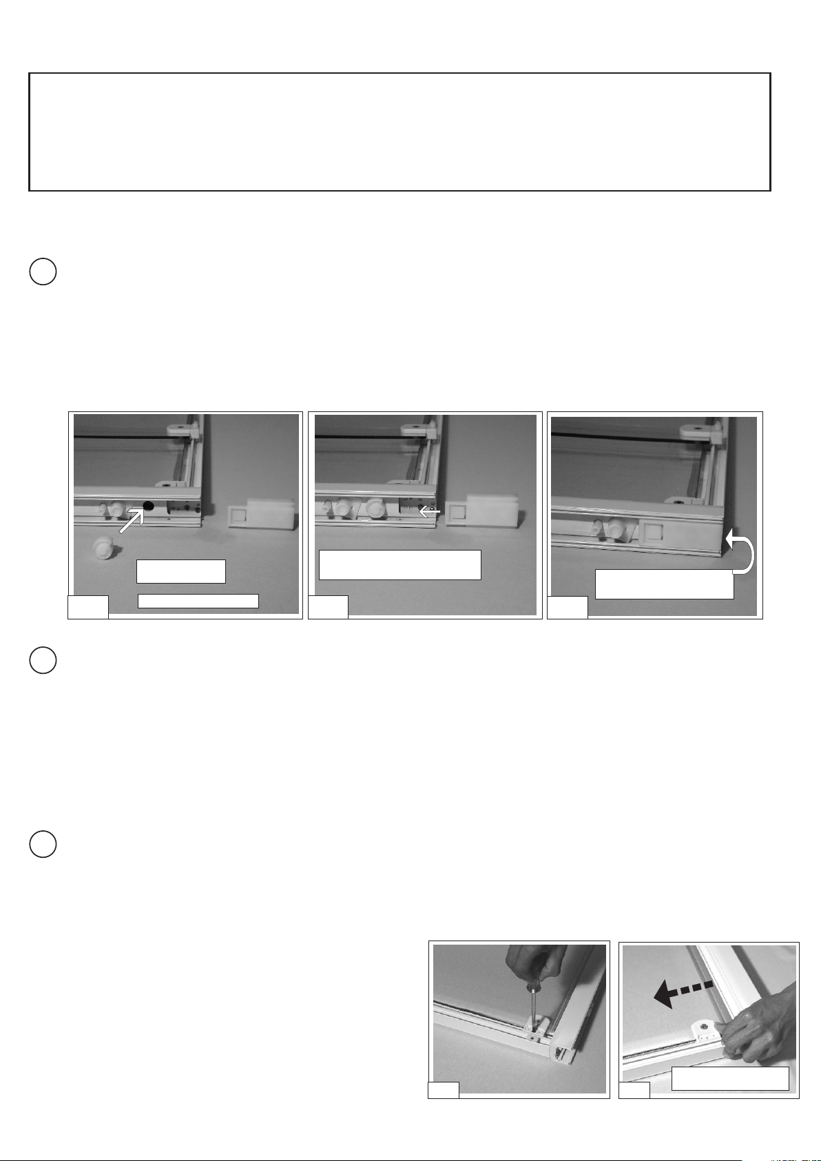
Remove the wheel patch
fixings from the door glass
using the 4mm allen key
supplied. Sit these patch fittings into
TOP rail upside down then turn the
right way around to lock them into the
rail.
Carefully feed the glass into
the unit and match up the top
holes with the wheel patches.
Screw the inner cover back on.
Ensure the shoulders of the patch
fittings are tight against the top edge
of the glass.
If the handing of the door glass is
being changed then you will need to
remove the quick release patches
and splash seal and ensure they are
to the bottom of the door with the
levers pointing towards each other.
FIT COVER CAPS, to all
patch fittings and each wallpost
Secure wallpost cover caps
using No.4 x 10mm long screws
provided.
FIT VERTICAL DOOR seal
onto the opposite edge of the
sliding door to the handle.
Position stop blocks to prevent the
handle of sliding door impacting on
edge of fixed panel, then tighten allen
key grub screws with 2.5mm Allen
Key.
TIP
If seals feel tight, then
wetting in clean water
will help. Ensure you do
not stretch the seals. Trim
to correct length.
Adjust the hanging of the door
so that the closing edge of the
glass meets the closing seal
evenly over it’s entire height. Gain
access to screw “A” by removing the
top patch cover.
SLIDING DOOR
VIEW
FROM INSIDE
TOP
TO RAISE THIS
SIDE OF DOOR
USE SCREW
‘A’
TO LOWER
THIS SIDE OF
DOOR USE
SCREW ‘B’
A
B
TO RAISE THIS
SIDE OF DOOR
USE SCREW
‘A’
TO LOWER
THIS SIDE OF
DOOR USE
SCREW ‘B’
A
B
A
B
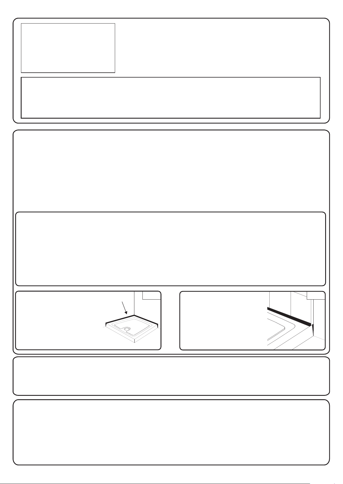
Roller bearing adjustment- using
screwdriver, loosen screw (do not remove), re-
position in slot and re-tighten.
Patch fitting adjustment- using allen key,
loosen screw (do not remove), lower glass and
re-tighten.
FIXED
DOOR
Silicone seal the wallposts.
Both wallposts should be
sealed vertically to the tiled /
panelled walls on the Outside &
Inside of the enclosure.
Silicone seal the enclosure
to the tray on the outside only
You should also seal the joint
as shown.
IMPORTANT!! Do not seal to the tray
on the inside, this will prevent drainage
of the frame work and will cause
leakage problems
Seal joint at both ends
of the bottom rail
Keep inner fixings
to hand when
positioning the
glass door
?
?
Check the running of the
door, vasaline can be applied to
the bottom track to improve the
sliding action
Check that the shim strip has
been installed under the bottom
rail
?Check that all the screws and
fittings are fully tightened
?Ensure that the quick release
levers are to the bottom of the
door
?Leave for 24hrs before use to
allow silicone sealant to cure
Bottom & Top
TIP
Support weight of
glass on your foot
when securing to the top
wheel patches
PLEASE ENSURE THAT AFTER ADJUSTMENT
ALL SCREWS ARE FULLY TIGHTENED
Table of contents
Popular Plumbing Product manuals by other brands

Pfister
Pfister Iyla LG49-TR0 Quick installation guide

Thetford
Thetford 19833 quick start guide

Crosswater
Crosswater 28-16-T installation instructions

agape
agape Fez 2 AFEZ001 instructions

Symmons
Symmons Origins 9600-P Operation & maintenance manual

American Standard
American Standard Cadet 1674 parts list