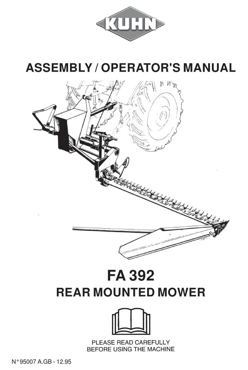
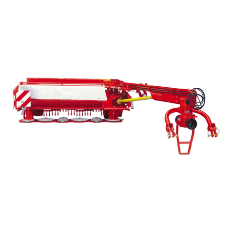
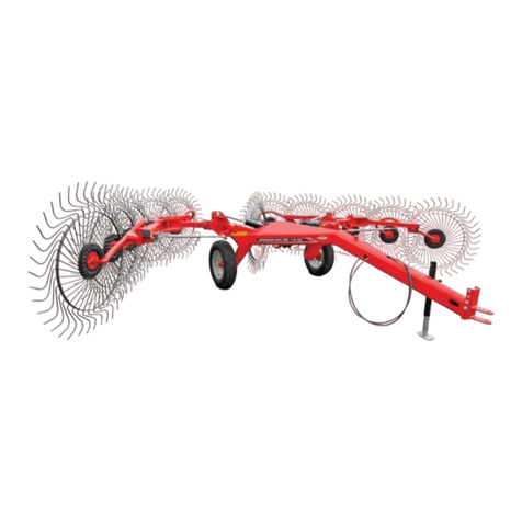
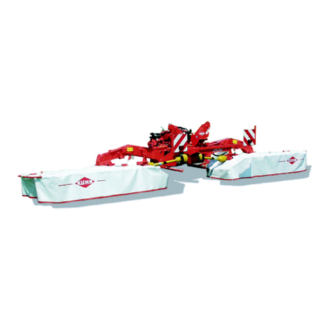
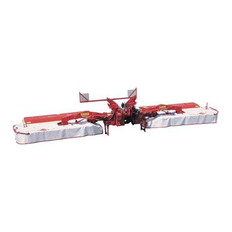
KUHN GMD 602 F User manual

ASSEMBLY / OPERATORS
MANUAL
FRONT MOUNTED MOWER
GMD 602 F - GMD 702 F - GMD 802 F
N° 95006 C.GB - 06.2001

DEAR OWNER,
In buying a KUHN machine you have chosen wisely. Into it have gone years of thought,
researchandimprovements.Youwillfind,ashavethousandsofownersallovertheworld,that
you have the best that engineering skill and actual field testing can produce. You have
purchased a dependable machine, but only by proper care and operation can you expect to
receive the performance and long service built into it.
This manual contains all the necessary information for you to receive full efficiency from your
machine.Theperformanceyougetfromthismachineislargelydependantuponhowwellyou
readandunderstandthismanualandapplythisknowledge.PleaseDONOTASSUMETHAT
YOU KNOW HOW TO OPERATE AND MAINTAIN YOUR MACHINE before reading this
manual carefully. KEEP THIS MANUAL AVAILABLE FOR REFERENCE.
YourKUHN dealerwillinstruct youonthegeneral operationofyourmachine. He isinterested
that you get the best performance possible and will be glad to answer any special questions
that may arise regarding the operation of the KUHN machine.
Your KUHN dealer can offer a complete line of genuine KUHN service parts.
These parts are manufactured and carefully inspected in the same factory that builds the
machine to assure high quality and accurate fitting of any necessary replacements.
When ordering service parts it is important that you indicate the type of machine concerned
and its serial number.
Forthisreasonpleasecompletethemodelidentificationplatediagrambelowwiththerequired
information. This will provide you with an easy reference for future service parts orders.
ABOUT IMPROVEMENTS
KUHN iscontinuallystriving to improveitsproducts and,therefore,reserves the righttomake
improvements or changes when it becomes practical to do so, without incurring any
obligations to make changes or additions to the equipment sold previously.

- 1 -
CONTENTS
Page
Safety notices 2
Safetydecals 8
Technicalspecifications 10
Signallingelements 11
Tractorfronthydraulicsrequirement 12
Adapting the mower to the tractor 13
Transportingthemower 19
Workingposition 20
Usingthemower 21
Adjustments 22
Detachingthemower 23
Lubrication 24
Maintenance 28
Inspectionofknives & securing elements 30
Storingthemower 32
Optionalequipment 32
Troubleshootingguide 33
Limitedwarranty 34
Copyright2001 KUHN S.A.

- 2 -
SAFETY
Theabovesymbolisusedthroughoutthismanualeverytimerecommendationsaremadeconcerningyoursafety,
the safety of others, or the good operation of the machine.
Theserecommendationsmustbe made known to all machine operators.
DESIGNATED USE OF THE MACHINE
TheGMD602F-GMD702F-GMD802Ffrontmountedmowersmustonlybeusedfortheworkwhichtheyhave
beendesigned:mowingonthegroundofhayfields,grasssilagefieldsandimprovedpasturesforthepurposeof
harvestingfodderforfeedinglivestock.
Themanufacturerisnotheldliableforanydamageresultingfrommachineapplicationsotherthanthosespecified
bythemanufacturer.
Any use other than the designated operation is at the risk and responsibility of the operator.
Designated use of the machine also means :
-followingoperation,maintenanceandrepairrecommendationsgivenbythemanufacturer;
-using only genuinespare parts, equipmentand accessories asdesignated by themanufacturer.
TheGMD602F-GMD702F-GMD802Ffrontmountedmowersmustonlybeoperated,maintainedandrepaired
by competent persons who are familiar with machine specifications and operation and are aware of any danger
involved.
Theoperatormustimperativelyrespectcurrentlegislationconcerning:
-accidentprevention,
- work safety,
-public traffic circulation.
All safety advice indicated on the machine must be strictly observed.
Themanufacturerisnotheldliableforanydamageresultingfrommachinemodificationscarriedoutbytheoperator
himselforbyathirdpartywithoutpreviouswrittenagreementfromthemanufacturer.
GENERAL SAFETY RECOMMENDATIONS
Beforeoperatingthemachine,alwaysensurethattractorandmachineareinaccordancewithworksafetyandroad
trafficregulations.

- 3 -
BASICPRINCIPLES
1. Inadditiontotherecommendationsgiveninthismanual,legislationonworksafetyandaccidentpreventionmust
alsobe respected.
2. Adviceis indicatedonthe machine, specifyingsafetyrecommendations in ordertoprevent accidents.
3. Beforetravellingonpublicroads,theoperatormustensurethatthemachineconformstoroadtrafficregulations.
4. Before starting work, the operator must be familiar with all machine controls, handling devices and their
functions. Once at work, it is too late to do so !
5. Donot wear loose clothingwhich could becomecaught up inmoving elements.
6. Useatractorequippedwithasafetycab.Keepwindowsandroofhatchclosedforreducedsoundlevelwhile
operatingthePTOdrivenimplement.
7. Beforestartingupthemachineandbeginningwork,checkthesurroundingarea(bewareofchildren!).Make
surethereissufficientvisibility.Keepallpeopleandanimalsawayfromthedangerzoneofthemachine(risk
ofprojection!)
8. Carryingpeople oranimals on themachine when workingorin transport isstrictly forbidden.
9. Machine must only be attached to tractor using means provided and in accordance with current safety
standards.
10. Whenattaching or removing the machine,placetheparkingstandinto the corresponding position.
11. Specialcare should be takenwhenattaching or removing themachinefromthe tractor.
12. Beforeattaching the machine, make surethatthemaximum permitted front axle weightandgrossweight of
thecombinationare not exceeded.
13. Donot exceed themaximumpermittedlength and widthauthorizedbyroad traffic regulations.
14. Beforetransportingthemachineonpublicroads,ensurethatalllegallyrequiredguardsandindicators(lights,
reflectors...) are in place andin good operation.
15. All operating controls (cords, cables, rods ...) must be positioned so that they cannot be set off accidently,
riskingaccidentor damage.
16. Before travelling on public roads, put the machine into its transport position as instructed in this operator’s
manual.
17. Neverleavethe tractorseatwhilethe machineisoperating.
18. Drive speed must be adapted to ground conditions as well as to roads and paths.
Alwaysavoidabruptchangesofdirection.
19. Precisionsteering,tractoradherence,roadholdingandefficientbrakingareinfluencedbythetypeofimplement,
weight, ballast of front axle, ground or road conditions. It is therefore of utmost importance to be cautious in
everygivensituation.
20. Beparticularlycautiouswhenturningcorners,payingattentiontomachineoverhang,length,heightandweight.
- 4 -
21. Beforeoperatingthemachine,ensurethat all safety guards are firmlyinplaceandingoodcondition.Ifworn
ordamaged,replaceimmediately.
22. Before operating the machine, check the tightness of all nuts and bolts, particularly on tool fixing elements
(blades, tines, knives, spades ...). Retighten if necessary.
23. Keepclearofthemachine operatingarea.
24. WARNING!Dangerofcrushing and shearingcanexistwhencomponentsareoperatedby hydraulic or
pneumaticcontrols.
25. Beforeleavingthetractororbeforeadjusting,maintainingorrepairingthemachine,turnofftheengine,remove
the ignition key and wait until all moving parts have come to a complete stop.
26. Donotstandbetweenthetractorandthemachineunlessthehandbrakeistightand/orstopshavebeenplaced
underthewheels.
27. Beforeany adjustments, maintenance orrepairsare carried out, ensurethatthemachine cannot be started
up accidentally.
ATTACHMENT
1. Whenattachingorremovingthemachinefromthetractor,positionhydraulicliftcontrolleverinsuchawaythat
it cannot be set off accidentally.
2. WARNING ! Danger of crushing and shearing can exist in the lifting zone of the 3-point linkage !
3. Donotstandbetweenthetractorandthemachinewhenoperatingtheoutercontrolleveroftheliftmechanism.
4. In transport, the machine lift mechanism should be stabilized by tractor tie rods to avoid floatation and side
shifting.
5. When transporting the machine in the raised position, lock the lift control lever in place.
POWERTAKE-OFF
1. Useonly the PTO shaftsupplied with the machineor recommended by themanufacturer.
2. PTO guards must always be in place and in good condition.
3. Checkfor correctPTOoverlapwhenatwork andintransport.
4. BeforeattachingorremovingthePTOshaft,disengagePTOshaft,turnoffengineandremoveignitionkey.
5. IfaprimaryPTOshaftisequippedwithaslipclutchorafreewheel,thesemustbefitted onthemachinePTO.

- 5 -
6. Ensure that PTO shaft is always correctly fitted and locked into place.
7. Make sure guards are correctly in place and secured with the safety chains provided.
8. Before engaging PTO, ensure that PTO speed (rotational frequency) and direction are in accordance with
manufacturer'srecommendations.
9. Beforeengaging PTO, keepallpeopleandanimals clear fromthemachine.
10. NeverengagePTOshaftwhentractormotoristurnedoff.
11. NeversurpassthePTOanglerecommendedbythemanufacturer.
12. WARNING!RotatingelementscancontinueturningmomentarilyafterPTOisdisengaged.Keepclearuntilall
rotating elements are at a standstill.
13. Whenremovingthe machine,placePTOshaftonthe supportsprovided.
14. Fit the safety cap on tractor PTO.
15. Replaceanyworn ordamagedPTOguards immediately.
HYDRAULIC SYSTEM
1. WARNING ! Hydraulic system is under pressure (maximum working pressure : 200 bars / 2900 psi).
2. When fitting hydraulic motors or cylinders, ensure that connections have been made correctly, as per
manufacturer’sinstructions.
3. Before connecting hoses to the tractor hydraulics, ensure that tractor and machine circuits are not under
pressure.
4. Itisstronglyrecommendedthattheoperatormarksthehydraulicconnectionsbetweentractorandmachineto
avoidmakingawrongconnection.WARNING!Functionscouldbereversed(forexample:lift/lower).
5. Regularly check the hydraulic hoses ! In case of normal wear, replace the hydraulic hoses every 5 years.
Damaged or worn hoses must immediately be replaced .
Whenreplacingthehydraulichoses,makesuretousehoseswiththespecificationsandqualityrecommended
bythemanufacturer of the machine.
6. Should a leak be found, take all necessary precautions to avoid accidents.
7. Any liquid under pressure (particularly oil from hydraulics) can penetrate the skin and cause severe injury. If
injured,see a doctor immediately,therecould be dangerofinfection.
8. Beforeany adjustments, maintenanceorrepairs are carried out,lowerthe machine, depressurize thecircuit,
turnofftheengineandremoveignitionkey.

- 6 -
MAINTENANCE
1. Before checking for any machine malfunction and before adjusting, maintaining or repairing the machine,
disengagePTO,turnoffengineandremoveignitionkey.
2. Check tightness of nuts and bolts regularly. Retighten if necessary.
3. If the machine is raised, prop it up in a stable position before carrying out any maintenance work.
4. Whenreplacingaworkingpart,wearprotectiongloves and only use standardized tools.
5. Itisforbiddentodiscardanyoil,greaseorfilters.Thesemustbegiventowastedisposalorganisationstoprotect
theenvironment.
6. Disconnect power source before any work is done to the electric system.
7. Check safety guardsregularly, particularly those that aresubject towear. Replace immediately if damaged.
8. Sparepartsusedmustbeinaccordancewithspecificationsandstandardsasdefinedbythemanufacturer.Use
onlygenuineKUHNparts!
9. Before any electric welding is carried out on tractor or attached machine, disconnect generator and battery
terminals.
10.Repairs on elements under pressure or tension (springs, accumulators etc.) must only be carried out by
competentpersonswithstandardizedequipment.
SPECIAL SAFETY RECOMMENDATIONS
1. Stay a safe distance away from the mower when discs are rotating.
2. For safe machine operation, it is imperative that cutting tools be fitted in accordance with the manufacturer’s
recommendations. Use only the tool outfit supplied with the machine.
3. Eachtimebeforeusingthemower,inspectconditionofcuttingelements(knives,discs).Replaceanymissing,
wornordamagedcutting elements immediately. Use onlygenuineKUHNspareparts.
4. Toavoidcreatingdangerousoutofbalanceforces,alwaysreplacemissing,damagedorwornknivesinpairs.
5. When replacing knives or discs, systematically inspect their securing elements as per the manufacturer’s
recommendations.
6. Regularly inspect the disc mower’s protection cover. Worn or damaged protection covers must be replaced
immediately.
7. Protectiondevices(suchasguards,shieldsetc.)areintendedtopreventstones,rocksorotherforeignobjects
frombeingprojected.Theyalsopreventaccesstothemachine’sdangerzones.Therefore,itisimperativethat
protectiondevicesare put in placeandproperly secured each timebeforeusing the machine.

- 7 -
8. Crushing and shearing zones which could cause serious bodily injury when changing the machine from
transport to work position and vice versa may exist. To prevent possible injury, be extra careful when
maneuveringand ensure thateveryoneisata safedistanceawayfromthemachine.
9. PTOdrivetothemowermustneverbeengagedunlessthecutterbarskidshoesareincontactwiththeground
andtheprotectivecoverisfoldeddown.
10. Ground of thepastures to bemown must befree of foreignobjects.
11. Even when the machine is used in accordance with it purpose, objects may be projected. It is therefore
imperativethateveryonebekeptawayfromthedangerzone,thatextracarebetakenandthatextra precaution
(such as safety indicators) be taken when mowing pastures alongside roads or near public areas (parks,
schools etc.).
12. Never mow in reverse.
13. Whendisengagingthe PTOdrive,movingpartscontinue torotateforsometime.Wait forallmovingpartsto
cometoa complete stop beforeapproachingthe machine.
14. Ifanobstructionishit,stopthetractorimmediately,disengagePTOdrive,turnoffengine,removeignitionkey
and wait for all moving parts to come to a complete stop.
Checktheentiremachineforanydamagebeforeresumingwork.
15. Itisstronglyrecommendedtohaveyourmachinecheckedbyyourdealeraftereachseason,especiallyblades
and discs and their fixing devices (nuts, bolts etc.).

- 8 -
SAFETY DECALS
THEFOLLOWINGSAFETYPICTORIALSHAVE BEEN PLACED ON YOUR MACHINE IN THE AREAS
INDICATED.THEYAREINTENDEDFORYOURPERSONALSAFETYANDFORTHESAFETYOFTHE
PEOPLE WORKING WITH YOU. THE TEXT SHOWN ON THEM GIVES THEIR PRECISE MEANING.
ENSURETHATTHESEPICTORIALS ARE ALWAYS LEGIBLE.IFTHEYARENOT, REPLACE THEM.
(OPTION)

- 9 -

- 10 -
GMD 602 F GMD 702 F GMD 802 F
Numberof discs 6 7 8
Cuttingwidth 2,40 m(7' 10") 2,80 m (9’ 2") 3,11 m(10' 2")
Transportwidth 2,25 m (7' 4") 2,66 m (8' 9") 2,99 m (9'10")
Discspeed(rotationalfrequency) 3011rpm(min-1)3011rpm(min-1)3011rpm(min-1)
TractorPTOpowerrequirement(asfrom) 31kW(42hp) 36 kW (49 hp) 41kW (56CV)
* PTOspeed(rotationalfrequency)
(rotating clockwise or counterclockwise)
- GMD 602 F - 702 F - 802 F [1000 rpm (min-1)]1000rpm(min-1)
- GMD 602 F - 702 F - 802 F [540 / 1000 rpm (min-1)]540or1000rpm(min-1)(option)
PrimaryP.TO.shaft 1 3/8" 6 splines
Lift system hydraulic hydraulic hydraulic
WeightwithPTOshaft(approx.) 735kg(1617lbs) 805kg (1771 lbs) 880kg(1936 lbs)
TECHNICAL SPECIFICATIONS
* Adjustment from factory : rotating clockwise (seen in direction of travel)

- 11 -
The GMD 802 F isstandard equippedwith a roadsignalling kit (no 107 6110).
For the GMD 602 F - 702 F the road signalling kit is available on option (see page 32).
Install the road signalling kit as described below :
- Fixthe 2signalling shields (1) on thesupports (2) on each side of themachine with 6 hexagonal screws(3) (M
10x20),6self-lockingnuts(M10)and2flatironbars(4)asshownonphoto2(redcornersmustbefacingupwards
andoutwards).
- Fit pilot lights (5) to the front side of the reflector boards (1) (see photo 2).
- Fit the left tail light (6) identified by its white (shown in grey on figure A) connector terminal marked “L” to
the rear side of the left reflector board (photo 3).
- Fittherighttaillight(marked“R”onitsblackconnectorterminal)totherearsideoftherightreflectorboard.
- Layoutthewiringharnessusingphotos2,3and4asaguide.Thewiringharnessisfixedontheframewith4clamp
collarsandself-adhesivecollarholders(7)andontothehydraulichoseswith9clampcollars(8)(length140mm)
(photos 2, 3 and 4). Make sure to thread the wiring harnesses through holes (O) (photos 2 and 3).
Plug the harness connectors to the corresponding pilot and tail lamp terminals .The locking tab (12) of the
female connector (13) must be fully engaged over the peg (14) of the male connector (15) (fig. A).
- Attach electric plug support (9) to the main frame with an original hexagon bolt (10) (photo 2).
NOTE: - A 7 pin socket is required at the front of the tractor in order to switch on the signalling element lights.
- When parking the machine, place plug (11) in its support (9) on the frame (photo 3).
SIGNALLING ELEMENTS
A
2
4
3

- 12 -
TRACTOR FRONT HYDRAULICS REQUIREMENT
5
PTOspeed(rotationalfrequency):
-1000rpm(min-1)todrivetheGMD602F-702F-802
F[1000 rpm (min-1)]
- 540min-1 or1000 min-1 to drive theGMD 602 F - 702
F - 802 F [540 / 1000 rpm (min-1)] (option).
Front hitch fitted with an A-frame, cat. 2 (ISO 11001).
Themachine issuppliedwithamale hydrauliccoupler
conformingto ISO5676. The tractoris to be equipped
withafemalecoupler(O)connectedinparallelwiththe
liftcylinders(photo5)forsimultaneousoperationofthe
fronthydraulicliftcylindersandthemachineheadstock
cylinder.
When operating with a tractor equipped with a
double acting hydraulic lift, the spool valve must
be set in the detented fourth position (float posi-
tion) to allow the cylinders to travel up and down
at will.

- 13 -
ADAPTING THE MOWER TO THE TRACTOR
1) ATTACHING MOWER TO TRACTOR
- Mountthe two hitchpins (T) onthe lower yokes(I)
oftheAframe(A)andsecurethembymeansofthe
roll pins (E) (diameter 8 x 45) (photo 6).
- Thenattachthesupportchains(R)tothehitchpins
(T)usingthebiggerendlink(photo6).Securethem
withthelockplates(V)andlinchpins(G)(photo6).
- Lower the tractor front hydraulic lift and attach the
mower(photo7).
- Connectthe PTO shaft.
- Threadsafetypin(S)throughhole(6)oflatch(4)of
triangularframe(A) (photo 7 andfig.7 A).
Note:Thesafetypin(S)hasa4mmdiameter.Ifhole
(6) of the A-frame used is not big enough to
accomodate this pin, counter drill it to 4.5 mm.
Check that stop (3) of the triangular frame (A) is
adjustedcorrectly.Forgoodoperationthisstopmust
bepositionedagainstlatch(4)sothatlatchisstillfree
topivotwhenpullinglever(5).
For adjustment, detach mower from the tractor and
proceedas follows :
- Untighten flush screw (2) so that stop (3) is free to
slide.
- Untighten lock nut of adjusting screw (1).
- Attach mower to the tractor.
- Rotate adjusting screw (1) until stop (3) contacts
latch(4).
- Checkthatlatch(4)isfreetooperatebypullinglever
(5).Ifoperationisdifficultuntightenscrew(1)halfa
turn.
- Detachmachinefromtractor.
- Tighten lock nut of adjusting screw (1) and tighten
flushscrew(2).
Regularly check that stop (3) is adjusted correctly,
especially each time the mower is adapted to a new
A frame (A). Readjust if necessary.
6
7

- 14 -
2) ATTACHING HYDRAULIC HOSE
Connecthydraulic hose (H)(photo8) to tractormak-
ing sure that hydraulic cylinders are not under
pressure.
Checkthatthelever(L)islockedinplaceintheforward
notch (A) of the selector plate (photo 8A).
Lift the mower.
Using levers (K) fold back the transport locks (J)
towards the rear, keeping them in this position
(photo9).
Attach both chains (R) to the highest possible
anchoragepointonthetractor(photo8).Chainlength
isright if distance (Y) isatleast 210 mm (8") (photo
9)when chains (R)aretight (photo 8).
9
8A
8

- 15 -
3) DIRECTION OF ROTATION
ComparetractorPTO and direction of disc rotation.
OUTSIDECONES MUSTTURN INWARDS.
If the central gearbox (N) must be repositioned, pro-
ceed as follows :
- Lower the tractor hitch completely so that the ma-
chine rests on the ground.
- Removethe protector(O)(photos10and10A).
- Unscrewthe4bolts(11)(M12),removethegearbox
(N)and thelateral PTO transmissionshaft (photos
10, 10 A and fig. 11).
- Changeover drain plug(12)anddipstickplug(13),
turn gearbox upside down. Reinstall gearbox in
place with the breather plug (13)facing upwards
(photos 10, 10 A and fig. 11)
- TightenthefourM12bolts(11)to12daNm(90ft.lbs)
andreassembleallothercomponentsagain.
4) PTO SHAFT
The PTO shaft is fitted with a 1 3/8 -6 spline yoke.
A13/8-21splineyokecanbeorderedasanoptionalitemunderpartNo.4603187fortheGMD602F-702F-802
F[1000 rpm (min-1)] and under part 4603 256 for the GMD 602 F - 702 F - 802 F [540/1000 rpm (min-1)].
a) GMD 602F-702F-802F [1000 rpm (min-1)]
Connect the PTO shaft (T) to the mower's central
gearcase(N)(photo12)andtothetractor's1000rpm
(min-1)PTOstub.
10
12
10A
(OPTION)

- 16 -
Make sure PTO shaft length is correct :
- When the PTO shaft is in its maximum extended position, a minimum tube overlap of 300 mm (12") must be
maintained.
- When the PTO shaft is in the maximum overlap position (retracted), tubes must not butt against the yokes.
A safety clearance (A) of 1 cm (1/2") must be maintained (fig. A).
b) GMD 602F-702F-802F [540 / 1000 rpm (min-1)] (option)
Connect the PTO shaft to the mower's central gearcase and to the tractor's 540 or 1000 rpm(min-1)PTO stub
(see photos 13, 14, 15 and 16).
PTOguard(P)mustbemountedonthestubusedtoconnectthePTOshaft(T)andthecap(C)
must be installed on the non used stub.
13 14
15 16

- 17 -
If this is not the case, shorten the two transmission tubes and the two guard tubes by the same length (fig.
B and C).
Beveland clean the transmission tubes(fig. D).
Grease the inside of the outer transmission tube (fig. E).
Neveroperate the PTO shaftattoogreatanangle(X) (+/- 30° maximum)(fig.17).
17
D

- 18 -
Failure to follow these basic PTO shaft adjustments will result in premature failure.
To avoid accidents which could be serious, make sure that guards are always correctly in
place and secured with the safety chains (photo 18 and 18 A). Damaged guards must be
replaced immediately.
18A
5) SAFETY CURTAINS
Before starting up the mower :
Make sure that all safety curtains are in the correct position.
19
18
This manual suits for next models
2
Table of contents
Other KUHN Lawn Mower manuals
Popular Lawn Mower manuals by other brands

Craftsman
Craftsman EZ3 917.259541 owner's manual

Texas A/S
Texas A/S Premium Series user manual

GreenWorks Pro
GreenWorks Pro 60V Pro Series Operator's manual

Craftsman
Craftsman 917.371790 owner's manual

Craftsman
Craftsman 917.28734 Operator's manual

Snapper
Snapper NZMJ23521KH, NZMJ25611KH Safety instructions & operator's manual