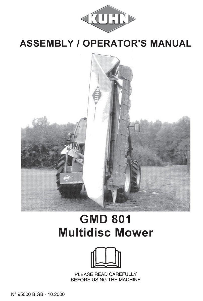
KUHN GMD 400 User manual

ASSEMBLY / OPERATOR'S MANUAL
GMD 400 - 500
GMD 400 HD - 500 HD
MULTIDISC MOWER
N° 95001 C.GB - 03.2003

DEAR OWNER,
In buying a KUHN machine you have chosen wisely. Into it have gone years of thought,
researchandimprovements.Youwillfind,ashavethousandsofownersallovertheworld,that
you have the best that engineering skill and actual field testing can produce. You have
purchased a dependable machine, but only by proper care and operation can you expect to
receive the performance and long service built into it.
This manual contains all the necessary information for you to receive full efficiency from your
machine.Theperformanceyougetfromthismachineislargelydependantuponhowwellyou
readandunderstandthismanualandapplythisknowledge.PleaseDONOTASSUMETHAT
YOU KNOW HOW TO OPERATE AND MAINTAIN YOUR MACHINE before reading this
manual carefully. KEEP THIS MANUAL AVAILABLE FOR REFERENCE.
YourKUHN dealerwillinstruct youonthegeneral operationofyourmachine. He isinterested
that you get the best performance possible and will be glad to answer any special questions
that may arise regarding the operation of the KUHN machine.
Your KUHN dealer can offer a complete line of genuine KUHN service parts.
These parts are manufactured and carefully inspected in the same factory that builds the
machine to assure high quality and accurate fitting of any necessary replacements.
When ordering service parts it is important that you indicate the type of machine concerned
and its serial number.
Forthisreasonpleasecompletethemodelidentificationplatediagrambelowwiththerequired
information. This will provide you with an easy reference for future service parts orders.
ABOUT IMPROVEMENTS
KUHN iscontinuallystriving to improveitsproducts and,therefore,reserves the righttomake
improvements or changes when it becomes practical to do so, without incurring any
obligations to make changes or additions to the equipment sold previously.

- 1 -
CONTENTS
Safety 2
Safetydecals 9
Assembly instructions 11
Technicalspecifications 12
Generalinformation 17
Fitting to the tractor 18
P.T.O.shaft 20
Workingpositionandadjustments 21
Transportandparkingthemachine 24
Operatingthemower 25
Lubrication 26
Adjustmentsandmaintenance 28
Optionalequipment 33
Troubleshootingguide 35
Storingthemower 36
Limitedwarranty 38
Copyright 2003 KUHN S.A.

- 2 -
SAFETY
Thesymbolaboveisusedthroughoutthismanualeverytimerecommendationsaremadeconcerningyoursafety,
the safety of others, or the good operation of the machine.
Theserecommendationsmust be made known to all machine operators.
DESIGNATED USE OF THE MACHINE
TheGMD400-500-400HD-500HDDiscMowersmustonlybeusedfortheworkwhichtheyhavebeendesigned:
mowingonthegroundofhayfields,grasssilagefieldsandimprovedpasturesforthepurposeofharvestingfodder
for feeding livestock.
Themanufacturerisnotheldliableforanydamageresultingfrommachineapplicationsotherthanthosespecified
bythemanufacturer.
Any use other than the designated operation is at the risk and responsibility of the operator.
Designated use of the machine also means :
-followingoperation,maintenanceandrepairrecommendationsgivenbythemanufacturer;
-using only genuinespare parts, equipmentand accessories asdesignated by themanufacturer.
TheGMD400-500-400HD-500HDDiscMowersmustonlybeoperated,maintainedandrepairedbycompetent
persons who are familiar with machine specifications and operation and are aware of any danger involved.
Theoperatormustimperativelyrespectcurrentlegislationconcerning:
-accidentprevention,
- work safety,
-public traffic circulation.
All safety advice indicated on the machine must be strictly observed.
Themanufacturerisnotheldliableforanydamageresultingfrommachinemodificationscarriedoutbytheoperator
himselforbyathirdpartywithoutpreviouswrittenagreementfromthemanufacturer.

- 3 -
GENERALSAFETYRECOMMENDATIONS
Before operating the machine, always ensure that tractor and machine are in accordance with work safety and
road traffic regulations.
BASICPRINCIPLES
1. Inadditiontotherecommendationsgiveninthismanual,legislationonworksafetyandaccidentprevention
mustalsoberespected.
2. Advice is indicated on the machine, specifying safety recommendations in order to prevent accidents.
3. Before travelling on public roads, the operator must ensure that the machine conforms to road traffic
regulations.
4. Before starting work, the operator must be familiar with all machine controls, handling devices and their
functions. Once at work, it is too late to do so !
5. Useatractorequippedwithasafetycab.Keepwindowsandroofhatchclosedforreducedsoundlevelwhile
operatingthePTOdrivenimplement.
6. Beforestartingupthemachineandbeginningwork,checkthesurroundingarea(bewareofchildren!).Make
surethereissufficientvisibility.Keepallpeopleandanimalsawayfromthedangerzoneofthemachine(risk
of projection!).
7. Carrying people or animals on the machine when working or in transport is strictly forbidden.
8. Machine must only be attached to tractor using means provided and in accordance with current safety
standards.
9. When attaching or removing the machine, place the parking stand into the corresponding position.
10. Special care should be taken when attaching or removing the machine from the tractor.
11. Before attaching the machine, ensure that the front tractor axle is sufficiently ballasted.
Ballastis to be placed onthesupportsprovidedinaccordancewithinstructions of the tractormanufacturer.
12. Donotsurpassthemaximumaxleloadortheoveralltransportweightasprescribedbythetractormanufacturer.
13. Do not surpass the maximum transport width authorized by road traffic regulations.
14. Beforetransportingthemachineonpublicroads,ensurethatalllegallyrequiredguardsandindicators(lights,
reflectors ...) are in place and in good operation.
15. All operating controls (cords, cables, rods ...) must be positioned so that they cannot be set off accidently,
risking accident or damage.
16. Beforetransportonpublicroads,locatethemachineintoitstransportpositionasinstructedinthisoperator’s
manual.
17. Neverleave thetractor seat while the machineis operating.

- 4 -
18. Drive speed must be adapted to ground conditions as well as roads and paths.
Always avoid abrupt changes of direction.
19. Precision steering, tractor adherence, road holding and efficient braking are influenced by the type of
implement,weight,ballastoffront axle,groundorroadconditions.Itis thereforeofutmostimportancetobe
cautious in every given situation.
20. Beparticularlycautiouswhenturningcorners,payingattentiontomachineoverhang,length,heightandweight.
21. Keep clear of the machine operating area.
22. WARNING ! Danger of crushing and shearing can exist when components are operated by hydraulic or
pneumaticcontrols.
23. Beforeleavingthetractororbeforeadjusting,maintainingorrepairingthemachine,turnofftheengine,remove
ignition key and wait until all moving parts have come to a complete stop.
24. Donotstandbetweenthetractorandthemachineunlessthehandbrakeistightand/orstopshavebeenplaced
underthewheels.
25. Beforeanyadjustments,maintenanceorrepairsarecarriedout,ensurethatthemachinecannotbestarted
up accidentally.
PRECAUTIONS TO BE TAKEN BEFORE OPERATING THE MACHINE
1. Do not wear loose clothing which could be caught up in moving parts.
2. Wear the individual protection equipment corresponding to the work which is planned (gloves, shoes, eye
protection, helmet, ear protectors...).
3. All operating controls (cords, cables, rods ...) must be positioned so that they cannot be set off accidentally,
causing accident or damage.
4. Beforeoperatingthe machine,checkthetightnessofall nutsandbolts,particularlyon rotatingparts(blades,
tines, knives, spades ...)
5. Before operatingthe machine, ensurethat allsafety guardsare firmlyin placeand ingood condition.If worn
ordamaged,replaceimmediately.

- 5 -
ATTACHMENT
1. Whenattachingorremovingthemachinefromthetractor,positionhydraulicliftcontrolleverinsuchawaythat
it cannot be set off accidentally.
2. Whenattachingthemachinetotractor3-pointlinkage,ensurethatdiameteroflinkpinscorrespondstodiameter
of ball joints.
3. WARNING ! Danger of crushing and shearing can exist in the lifting zone of the 3-point linkage !
4. Donotstandbetweenthetractorandthemachinewhenoperatingtheoutercontrolleveroftheliftmechanism.
5. In transport, the machine lift mechanism should be stabilized by tractor tie rods to avoid floatation and side
shifting.
6. When transporting the machine in the raised position, lock the lift control lever in place.
7. Donotoperatethemachinewithnarrowwheeltracktractorswhenworkingortransportingonunevenorsloping
terrain.
POWERTAKE-OFF
1. OnlyusePTO shaft supplied withthemachineor recommended by the manufacturer.
2. PTO guards must always be in place and in good condition.
3. Checkfor correctPTOoverlapwhenat workandintransport.
4. BeforeattachingorremovingthePTOshaft,disengagePTOshaft,turnoffengineandremoveignitionkey.
5. IfaprimaryPTOshaftisequippedwithaslipclutchorafreewheel,thesemustbefitted onthemachinePTO.
6. Ensure that PTO shaft is always correctly fitted and locked into place.
7. Make sure guards are correctly in place and secured with the safety chains provided.
8. Before engaging PTO, ensure that PTO frequency and direction are in accordance with manufacturer's
recommendations.
9. Beforeengaging PTO,keepallpeopleandanimals clearfromthemachine.
10. NeverengagePTOshaftwhentractormotoristurnedoff.

- 6 -
11. NeversurpassPTOanglerecommendedbythemanufacturer.
12. WARNING!RotatingelementscancontinueturningmomentarilyafterPTOisdisengaged.Keepclearuntilall
rotating elements are at a standstill.
13. Whenremovingthemachine,locatePTO shaft on thesupportsprovided.
14. Fit safety cap on tractor PTO.
15. Replaceanywornor damagedPTOguardsimmediately.
HYDRAULICSYSTEM
1. WARNING! Hydraulicsystem is underpressure(maximum working pressure: 200 bars/2900psi).
2. When fitting hydraulic motors or cylinders, ensure that connections have been made correctly, as per
manufacturer’sinstructions.
3. Before connecting hoses to the tractor hydraulics, ensure that tractor and machine circuits are not under
pressure.
4. Itisstronglyrecommendedthattheoperatormarksthehydraulicconnectionsbetweentractorandmachineto
avoidmakingawrongconnection.WARNING!Functionscouldbereversed(forexample:lift/lower).
5. Regularlycheckthehydraulichoses!Replacethehydraulichosesevery5years.Damagedorwornhoses must
immediatelybe replaced .
Whenreplacingthehydraulichoses,makesuretousehoseswiththespecificationsandqualityrecommended
bythe manufacturer of themachine.
6. Should a leak be found, take all necessary precautions to avoid accidents.
7. Any liquid under pressure (particularly oil from hydraulics) can penetrate the skin and cause severe injury. If
injured,see a doctor immediately,therecould be dangerofinfection.
8. Beforeany adjustments, maintenanceorrepairs are carried out,lowerthe machine, depressurize thecircuit,
turnofftheengineandremoveignitionkey.

- 7 -
MAINTENANCE
1. Beforecheckinganymachinemalfunctionandbeforeadjusting,maintainingorrepairingthemachine,disengage
PTO,turnoffengineandremoveignitionkey.
2. Check tightness of nuts and bolts regularly. Retighten if necessary.
3. If the machine is raised, prop it up in a stable position before carrying out any maintenance work.
4. Whenreplacingaworkingpart,wearprotectiongloves and only use standardized tools.
5. Itisforbiddentodiscardanyoil,greaseorfilters.Thesemustbegiventowastedisposalorganisationstoprotect
theenvironment.
6. Disconnect power source before any work is done on the electric system.
7. Check safety guardsregularly, particularly those that aresubject towear. Replace immediately if damaged.
8. Sparepartsusedmustbeinaccordancewithspecificationsandstandardsasdefinedbythemanufacturer.Use
onlygenuineKUHNparts!
9. Before any electric welding is carried out on tractor or attached machine, disconnect generator and battery
terminals.
10.Repairs on elements under pressure or tension (springs, accumulators etc.) must only be carried out by
competentpersonswithstandardizedequipment.
SPECIAL SAFETY RECOMMENDATIONS
1. Use a tractor equipped with an enclosed cab with windows made of safety glass and kept closed. It is
recommendedtofitpolycarbonatescreensinsidethetractorsafetycab'ssideandrearwindowsortoinstallmesh
guardson the exteriorof them.
2. Stay a safe distance away from the mower when discs are rotating.
3. For safe machine operation, it is imperative that cutting tools be fitted in accordance with the manufacturer’s
recommendations. Use only the tool outfit supplied with the machine.
4. Eachtimebeforeusingthemower,inspectconditionofcuttingelements(knives,discs).Replaceanymissing,
wornordamagedcutting elements immediately. Use onlygenuine KUHNspareparts.
5. Toavoidcreatingdangerousoutofbalanceforces,alwaysreplacemissing,damagedorwornknivesinpairs.

- 8 -
6. When replacing knives or discs, systematically inspect their securing elements as per the manufacturer’s
recommendations.
7. Regularly inspect the disc mower’s protection cover. Worn or damaged protection covers must be replaced
immediately.
8. Protectiondevices(suchasguards,shieldsetc.)areintendedtopreventstones,rocksorotherforeignobjects
frombeingprojected.Theyalsopreventaccesstothemachine’sdangerzones.Therefore,itisimperativethat
protectiondevicesare put in placeandproperly secured each timebeforeusing the machine.
9. Crushingandshearingzoneswhichcouldcauseseriousbodilyinjurywhenchangingthemachinefromtransport
towork positionandviceversamay exist. Topreventpossibleinjury,be extracarefulwhenmaneuveringand
ensure that everyone is at a safe distance away from the machine.
10.PTOdrivetothemowermustneverbeengagedunlessthecutterbarskidshoesareincontactwiththeground
andtheprotectivecoverisfoldeddown.
11.Groundof the pastures to be mown mustbe free offoreign objects.
12.Evenwhenthemachineisusedinaccordancewithitpurpose,objectsmaybeprojected.Itisthereforeimperative
thateveryonebekeptawayfromthedangerzone,thatextracareistakenandthatextra precaution(suchas
safetyindicators)betakenwhenmowingpastures alongsideroadsor nearpublicareas(parks,schoolsetc.).
13.Nevermowinreverse.
14.WhendisengagingthePTOdrive,movingpartscontinuetorotateforsometime.Waitforallmovingpartstocome
toacompletestop before approaching the machine.
15.Ifanobstructionishit,stopthetractorimmediately,disengagePTOdrive,turnoffengine,removeignitionkey
and wait for all moving parts to come to a complete stop.
Checktheentiremachineforanydamagebeforeresumingwork.
16.Itisstronglyrecommendedtohaveyourmachinecheckedbyyourdealeraftereachseason,especiallyblades
and discs and their fixing devices (nuts, bolts etc.).

- 9 -
SAFETY DECALS
THEFOLLOWINGSAFETY PICTORIALS HAVE BEEN PLACED ON YOUR MACHINE IN THE AREAS
INDICATED.THEYAREINTENDEDFORYOURPERSONALSAFETYANDFORTHESAFETYOFTHE
PEOPLE WORKING WITH YOU. THE TEXT SHOWN ON THEM GIVES THEIR PRECISE MEANING.
KEEP THE PICTORIALS LEGIBLE. IF THEY ARE NOT, REPLACE THEM.

- 10 -
8

- 11 -
TECHNICAL SPECIFICATIONS
TYPE GMD 400 - 400 HD GMD 500 - 500 HD
Number of discs 4 5
Width of cut 1.60 m (5' 3") 2.00 m (6'7")
PTOpowerrequirement 21 kW (28 hp) 25 kW (35 hp)
Disc frequency (at 540 min-1) 2986min-1
Width in transport position 0.23m (9") wider than tractor width *
Lift system hydraulic
Weight: - GMD 400 - 500 380 kg (836 lbs) 427 kg (939 lbs)
- GMD 400 HD - 500 HD 386 kg (849 lbs) 434 kg (955 lbs)
Bevel gearbox oilcapacity 0.25 litre
Oil quality : SAE 80 W EP (GL4) 0.53 US Pint / 0.43 Imp Pint
Cutterbar oil capacity 1.4 litre 1.7 litre
Oil quality : SAE 80 W EP (GL4) 3.0 US Pint / 2.5 Imp Pint 3.6 US Pint / 3.0 Imp Pint
* Applicable if machine is attached in such a way that a 5 cm / 2" distance «A» is respected (see page 18).

- 12 -
ASSEMBLY
TofacilitateshippingoftheGMD400-500-400HD-500HDdiscmowers,certainpartsorassembliesarepartially
disassembledto reduce bulk.To assemble theseparts proceed asfollows :
1. Mounting chassis to cutterbar
Makesurethattheboreofnylonbushingsiscleanandwellgreased.Removeprotectivepaintfromthefrontcover
ofbevelgearboxwherebushingsmakecontact.Chockchassis.Pullparkingstand(C)outwardsandswingitdown.
Attachchassistocutterbarwith2self-lockingscrews(B) (M16x50)and2washers(A)(dia.16.5x60)asshown
inphoto 1 andfigure 1. Torque: 30 daNm/220 ft.lbs.
For your safety be sure to chock chassis correctly.
2. Assembly of belt shield, belts and
hydraulic hose
- Installpawl(L)andmanoeuveringcord(H)asshown
on photo 1.
- Installtheinnerbeltshield(D)(photo2)inplaceand
securewiththe3spacer bolts(E)tapedon thestop
chain Torque to 5 daNm / 40 ft.lbs.
- Installclosingplate(F)equippedwithelasticnut as
shown in photo 2.
- Attachthelatch(L)tensionspring(R)(photo1)tothe
innerbeltshieldat(O)(photo2)usingasplitpin(dia.
4x22mm)provided.
- Fix hose (Z) to cylinder using a hollow screw and a
copper washer on each side of the banjo joint
(photo 2).

- 13 -
- Install belts (G) (photo 2) on pulleys and tension
thembylooseningthe2nuts(N)andtighteningnut
(S)(photo3).
- Belttensioniscorrectifdeflectiondoesnotexceed
10mm(2/5")whenbeltispresseduponwithaforce
of 3.5 daNm (8 ft.lbs) at mid distance between
pulleys.
- Whencorrecttensionhasbeenobtained,tightenthe
2 nuts (N) (photo 3).
3. Frame pipe and lift bracket assembly
- Attachouterbeltshield(E)with3washersand3cap
nuts (I)(photo 4). Torque to 5 daNm / 40 ft.lbs.
- Assembleclosingplate(F)(photo2)andouterbelt
shield with one self-locking screw (K) (M 8 x 16)
(photo4).
- Attachliftbracket(C)(photo6)usingaxleandsplit
pinsprovided.
4. Compensating spring, inner shoe and
inner swath board assembly
- Placethecutterbarintheverticalposition.Connect
compensatingspringrod(F)(photo7)toframepipe
using axle and 2 split pins provided.
- Attach frame pipe (A) (photo 5) to bevel gearbox
using4(M12x35)bolts(B).Tightento14daNm/100
ft.lbs.
6

- 14 -
- Attachtheinnerswathboard(D)(photo8A)inplace
using 4 (M10 x 20) round head bolts (E), 4 plain
washers and 4 self-locking nuts. Tighten all inner
swathboardbolts(T).
5. Installing outer disc with cone and outer swath wheel
- Fitinnershoe(I)bymeansof4cupsquarebolts(J)
(M10x25)and4selflockingnuts(M10)(photo8).
- OntheGMD500-500HDattachtheouterdiscwith
cone using 4 hexagon screws (M 12 x 20) and 4
conicalspringwashers (position the conicalcentre
at the top) so that its largest diameter is positioned
at a right angle in relation to the adjacent disc (see
pictorialopposite).Tightenat12daNm(90ft.lbs).
- Attachswathwheelassembly(U)toouterskidshoe
(photo 9) with 2 cup square bolts (V) (M 12 x 35), 2
conicalwashers(dia.13mm)and2self-lockingnuts
(M12). Torque : 8.5 daNm/65ft.lbs.
Before tightening screws (V), make sure that disc
does not come into contact with cone cover or
knives.
Keep to a distance of X = 15 to 25 mm / 5/8" - 1".
8A
9A
9

- 15 -
The angular position of the swath wheel compared to the cutterbar can be adapted to working
conditionsenablinga regular flow ofthecut crop towards therear.
Position the swath wheel so that maximum angle (A') (fig. 9 A) is obtained. In difficult working
conditions (long, dense, bent over crops) position it towards minimum angle (A) (fig. 9 A).
6. Safety guard and locking device assembly
- Attachthefrontsafetybar(B)toits2hinges(C)with
the3cupsquarebolts(P)(M10x25),3self-locking
nuts(O)(M10)and3flatwashers(Q) (diameter11
x 24 x 2) (fig. 10).
- Thenattachthepre-assembledfrontsafetybar(B)
at(N)with2hexagonalscrews(M12x75)andself-
lockingnuts(M12)(photo11).Donottightenthese
2screwscompletely,sothatthefrontsafetybarcan
still pivot.
- Next attach rear safety bar (A) with 3 round head
bolts(P)(M10x25),3self-lockingnuts(O)(M10)
and3flatwashers(Q)(diameter11x24x2)(fig.10
andphoto11).Fitend-plug(Z)onrearsafetybar
(A)(photo11).

- 16 -
- Installcover(D)asshowninphoto12.BucklestrapsaroundthepipeframeatE.Bucklestraps(F)aroundfront
and rear safety bar. All these straps are attached to the underneath of the safety cover.
- Punch 3 holes in the safety cover at (G) and use 3 cup square bolts (R) (M 10 x 35) with self-locking nuts (0)
(M10)(fig.10)andplainwashers(Q)(dia.11x24x2)toattachthefollowingcomponentsontheoutsidearms
of the safety bars : safety guard locking device (S) ; safety cover (D) ; stop rod (J) (see fig. 10 and also refer
to photos 11, 12 and 13).
Note : Makesurethatthepivotaxisofthesafetyguardlockingdevice(S)islinedupwiththepivotaxis(N)ofthe
frontsafetybarbeforetighteningself-lockingnuts(O).
Neveroperate themowerwithout theprotectioncover inplaceand thepivotingfront
protector lowered. Do not lean against or stand on the guard cover.
The safety guard locking device is operated with an
18mmboxspanner(T)tobestoredinholder(U)(photo
14).

- 17 -
GENERAL INFORMATION
1. MinimumtractorPTOpowerrequirementshouldbe
21 kW (28 hp) for the GMD 400 - 400 HD and
25 kW (35 hp) for the GMD 500 - 500 HD.
If the tractor engine rating is insufficient, quality of
work will not be satisfactory.
2. GMD 400 - 500 - 400 HD - 500 HD Disc Mowers
can only be operated on tractors equipped with a
standard540min-1 PTOfrequency and a standard
category 1 or category 2 3-point attachment.
Category 2 lower link bushes (590 010 00) are
supplied with the machine for attachment to
tractors with category 2 linkages.
3.TheGMD 400-500-400HD-500HDareequipped
withadjustablelowerlinkpinsallowingthemachines
tobeoffset50mm(2")totheleftandtotherightwhen
mountedtoacategory2linkageand114mm(4.5")
to the left when mounted to a category 1 linkage.
ToadjustlowerlinkpinsA,unscrewcounter nut (C)
and hexagon screw (B) (photo15 andfig. 15 A).
Displacepinsasshowninthefollowingdrawingand
retightenscrews andnuts.
Never mow in stony or rocky
grounds.

- 18 -
ATTACHING THE MOWER TO THE TRACTOR
ATTACHMENT OF LOWER LINKS AND
POSITIONNING OF LINK PINS :
Followfig.1forcategory1tractorswithnarrowwheel
track.
Followfig. 2 forcategory1 tractorswithwiderwheel
track.
Followfig.3forcategory2tractorswithnarrowwheel
track.
Follow fig. 4 for category 2 tractors with standard
wheeltrack.
Follow fig. 5 for category 2 tractors with wide wheel
track.
NOTE : Always attach machine in such a way that
distanceAisapproximately5cm(2")andmakesure
that check chain (C) (photo 21, page 22) is always
correctlyattached.
Other manuals for GMD 400
1
This manual suits for next models
3
Table of contents
Other KUHN Lawn Mower manuals