KUHN GA 300 GT User manual

ASSEMBLY/OPERATOR'SMANUAL
GA 300 GT GYRORAKE
No 95312 A.GB - 01.97

DEAR OWNER,
In buying a KUHN machine you have chosen wisely. Into it have gone years of thought,
researchandimprovements.Youwillfind,ashavethousandsofownersallovertheworld,that
you have the best that engineering skill and actual field testing can produce. You have
purchased a dependable machine, but only by proper care and operation can you expect to
receive the performance and long service built into it.
This manual contains all the necessary information for you to receive full efficiency from your
machine.Theperformanceyougetfromthismachineislargelydependantuponhowwellyou
readandunderstandthismanualandapplythisknowledge.PleaseDONOTASSUMETHAT
YOU KNOW HOW TO OPERATE AND MAINTAIN YOUR MACHINE before reading this
manual carefully. KEEP THIS MANUAL AVAILABLE FOR REFERENCE.
YourKUHN dealerwillinstruct youonthegeneral operationofyourmachine. He isinterested
that you get the best performance possible and will be glad to answer any special questions
that may arise regarding the operation of the KUHN machine.
Your KUHN dealer can offer a complete line of genuine KUHN service parts.
These parts are manufactured and carefully inspected in the same factory that builds the
machine to assure high quality and accurate fitting of any necessary replacements.
When ordering service parts it is important that you indicate the type of machine concerned
and its serial number.
Forthisreasonpleasecompletethemodelidentificationplatediagrambelowwiththerequired
information. This will provide you with an easy reference for future service parts orders.
ABOUT IMPROVEMENTS
KUHN iscontinuallystriving to improveitsproducts and,therefore,reserves the righttomake
improvements or changes when it becomes practical to do so, without incurring any
obligations to make changes or additions to the equipment sold previously.

- 1 -
CONTENTS
PAGE
Safety 2
Safetydecals 7
Technicalspecifications 9
Assembly 9
Attachment 12
- Fitting to tractor 12
-PTO transmission shaft 13
Workingpositionandadjustments 14
Operation 15
Forwardspeed 15
Swathscreen 16
Transport 16
Parking 17
Lubrication 17
Importantrecommendations 18
Optionalequipment 18
Conditionsoflimitedwarranty 19
Copyright1997 KUHN S.A.

- 2 -
SAFETY
Theabovesymbolisusedthroughoutthismanualeverytimerecommendationsaremadeconcerningyoursafety,
the safety of others, or the good operation of the machine.
Theserecommendationsmustbemadeknown to all machine operators.
DESIGNATED USE OF THE MACHINE
TheGA300GTGyrorakemustonlybeusedfortheworkforwhichithasbeendesigned:rakingonthegroundand
formingwindrowsofpre-mowedfodderandstraw.
Themanufacturerisnotheldliableforanydamageresultingfrommachineapplicationsotherthanthosespecified
bythemanufacturer.
Any use other than the designated operation is at the risk and responsibility of the operator.
Designated use of the machine also means :
-followingoperation,maintenanceandrepairrecommendationsgivenbythemanufacturer;
-using only genuinespare parts, equipmentand accessories asdesignated by themanufacturer.
TheGA300GTGyrorakemustonlybeoperated,maintainedandrepairedbycompetentpersonswhoarefamiliar
withmachinespecificationsandoperationandareawareofanydangerinvolved.
Theoperatormustimperativelyrespectcurrentlegislationconcerning:
-accidentprevention,
- work safety,
-public traffic circulation.
All safety advice indicated on the machine must be strictly observed.
Themanufacturerisnotheldliableforanydamageresultingfrommachinemodificationscarriedoutbytheoperator
himselforbyathirdpartywithoutpreviouswrittenagreementfromthemanufacturer.

- 3 -
GENERAL SAFETY RECOMMENDATIONS
Beforeoperatingthemachine,alwaysensurethattractorandmachineareinaccordancewithworksafetyandroad
trafficregulations.
BASICPRINCIPLES
1. Inadditiontotherecommendationsgiveninthismanual,legislationonworksafetyandaccidentpreventionmust
alsobe respected.
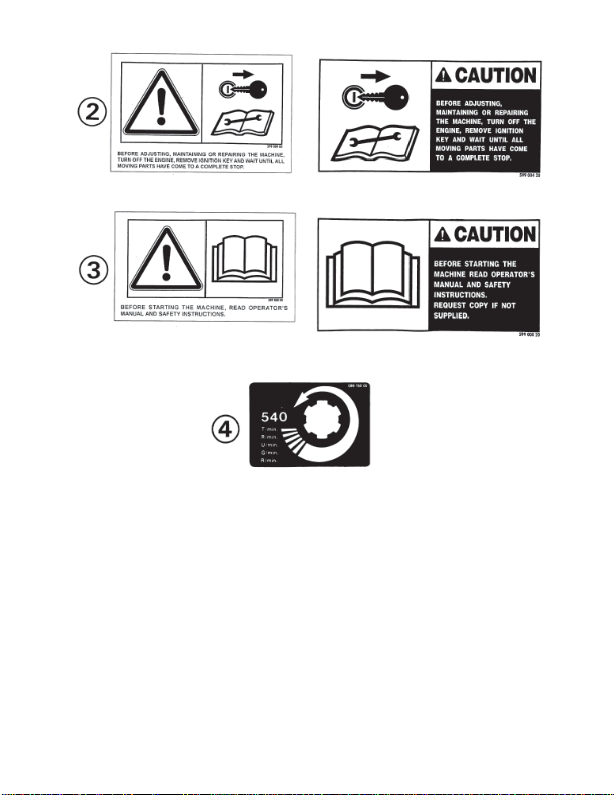
2. Adviceis indicated on themachine, specifying safety recommendationsin order to preventaccidents.
3. Beforetravellingonpublicroads,theoperatormustensurethatthemachineconformstoroadtrafficregulations.
4. Before starting work, the operator must be familiar with all machine controls, handling devices and their
functions. Once at work, it is too late to do so !
5. Donot wear loose clothing whichcould become caughtup in movingelements.
6. Useatractorequippedwithasafety cab. Keep windows and roof hatchclosedforreducedsoundlevelwhile
operatingthePTOdriveimplement.
7. Beforestarting upthemachineand beginningwork,checkthesurroundingarea(bewareofchildren!).Make
sure there is sufficient visibility.
Keepall people andanimals away fromthedanger zone ofthe machine (riskof projection !)
8. Carryingpeople or animalson the machinewhen working or intransport is strictlyforbidden.
9. Machine must only be attached to tractor using means provided and in accordance with current safety
standards.
10. Whenattachingor removing the machine, placetheparkingstandinto the corresponding position.
11. Specialcare should be takenwhenattachingor removing the machinefromthe tractor.
12. Before attaching the machine, ensure that the front tractor axle is sufficiently ballasted.
Ballast is to be placed on the supports provided in accordance with instructions of the tractor manufacturer.
13. Donotsurpassthemaximumaxleloadortheoveralltransportweightasprescribedbythetractormanufacturer.
14. Donot exceed the maximumtransportwidthauthorized by roadtrafficregulations.
15. Beforetransportingthemachineonpublicroads,ensurethatalllegallyrequiredguardsandindicators(lights,
reflectors...) are in place andin good operation.
16. Alloperatingcontrols(cords,cables,rods...)mustbepositionedsothattheycannotbesetoffaccidently,risking
accidentordamage.

- 4 -
17. Before traveling on public roads, put the machine into its transport position as instructed in this operator’s
manual.
18. Neverleavethe tractorseatwhilethemachine isoperating.
19. Drive speed must be adapted to ground conditions as well as to roads and paths.
Alwaysavoidabruptchangesofdirection.
20. Precisionsteering,tractoradherence,roadholdingandefficientbrakingareinfluencedbythetypeofimplement,
weight,ballastoffrontaxle,groundorroadconditions.Itisthereforeofutmostimportancetobecautiousinevery
givensituation.
21. Beparticularlycautiouswhenturningcorners,payingattentiontomachineoverhang,length,heightandweight.
22. Beforeoperatingthemachine, ensurethat allsafetyguardsarefirmlyinplaceand in good condition. If worn
ordamaged,replaceimmediately.
23. Beforeoperatingthemachine,checkthetightnessofallnutsandbolts,particularlyonfixingelements(blades,
tines, knives, spades ...)
24. Keepclearofthemachineoperatingarea.
25. WARNING ! Danger of crushing and shearing can exist when components are operated by hydraulic or
pneumaticcontrols.
26. Beforeleavingthetractororbeforeadjusting,maintainingorrepairingthemachine,turnofftheengine,remove
the ignition key and wait until all moving parts have come to a complete stop.
27. Donotstandbetweenthetractorandthemachineunlessthehandbrakeistightand/orstopshavebeenplaced
underthewheels.
28. Beforeanyadjustments,maintenanceorrepairsarecarriedout,ensurethatthemachinecannotbestartedup
accidentally.
ATTACHMENT
1. Whenattachingorremovingthemachinefromthetractor,ensurethatthemachinecannotmoveunexpectedly
(securewithwedges if necessary).
2. Donotexceedthemaximumallowabledownpressureappliedbythemachinedrawbaronthetractorhitchpoint.
3. Ensurethatverticalandhorizontalpivotanglesbetweenmachinetongueandtractorhitchpointaresufficientto
allowsafeoperation.

- 5 -
POWERTAKE-OFF
1. Useonly the PTO shaftsupplied with the machineor recommended by themanufacturer.
2. PTO guards must always be in place and in good condition.
3. Checkforcorrect PTOoverlapwhenatworkand intransport.
4. BeforeattachingorremovingthePTOshaft,disengagePTOshaft,turnoffengineandremoveignitionkey.
5. IfaprimaryPTOshaftisequippedwithaslipclutchorafreewheel,thesemustbefittedonthemachinePTO.
6. Ensure that PTO shaft is always correctly fitted and locked into place.
7. Make sure guards are correctly in place and secured with the safety chains provided.
8. Before engaging PTO, ensure that PTO speed and direction are in accordance with manufacturer's
recommendations.
9. BeforeengagingPTO, keepallpeopleandanimalsclearfrom themachine.
10. NeverengagePTOshaftwhentractorengineisturnedoff.
11. NeversurpassthePTOanglerecommendedbythemanufacturer.
12. WARNING!RotatingelementscancontinueturningmomentarilyafterPTOisdisengaged.Keepclearuntilall
rotating elements are at a standstill.
13. Whenremovingthemachine,placePTOshaftonthesupportsprovided.
14. Fit the safety cap on tractor PTO.
15. ReplaceanywornordamagedPTOguardsimmediately.

- 6 -
TIRES
1. Beforeanyworkisperformedonthewheels,ensurethatthemachinerestsonthegroundandisperfectlystable
so that it cannot move accidentally (put wedges in place).
2. Assembly,disassemblyandrepairofwheelsandtiresmustonlybecarriedoutbycompetentpersonswhoare
equippedwithstandardizedtools.
3. Checktirepressureregularly!
Respectmanufacturer’srecommendationsontirepressure.
MAINTENANCE
1. Before checking for any machine malfunction and before adjusting, maintaining or repairing the machine,
disengagePTO,turnoffengineandremoveignitionkey.
2. Check tightness of nuts and bolts regularly. Retighten if necessary.
3. If the machine is raised, prop it up in a stable position before carrying out any maintenance work.
4. Whenreplacingaworkingpart,wearprotectionglovesandonly use standardized tools.
5. Itisforbiddentodiscardanyoil,greaseorfilters.Thesemustbegiventowastedisposalorganisationstoprotect
theenvironment.
6. Disconnect power source before any work is done to the electric system.
7. Checksafety guardsregularly, particularly those that aresubject to wear. Replace immediatelyif damaged.
8. Sparepartsusedmustbeinaccordancewithspecificationsandstandardsasdefinedbythemanufacturer.Use
onlygenuine KUHNparts!
9. Before any electric welding is carried out on tractor or attached machine, disconnect generator and battery
terminals.
10. Repairs on elements under pressure or tension (springs, accumulators etc...) must only be carried out by
competentpersonswithstandardizedequipment.

- 7 -
SAFETY DECALS
THEFOLLOWINGSAFETYPICTORIALSHAVEBEENPLACEDON YOUR MACHINE IN THE AREAS
INDICATED.THEYAREINTENDEDFORYOURPERSONALSAFETYANDFORTHESAFETYOFTHE
PEOPLE WORKING WITH YOU. THE TEXT SHOWN ON THEM GIVES THEIR PRECISE MEANING.
ENSURETHATTHESEPICTORIALS ARE ALWAYS LEGIBLE.IFTHEYARENOT, REPLACE THEM.

- 8 -

- 9 -
Mounting the wheels
Slidethehubprotectorplug(01),thenthegreyprotector
plug (02) onto the wheel column (N) (see figure
opposite). Fill wheel caps (Q) with grease. Also
grease the space between both bearings located
inside the rims. Mount the 2 wheels (L) to wheel
column (N). Insert bushes (O) and screw on low
hexagon nut (P) (M 16). Tighten to 10 daNm/75
ft.lbs.Fitwheelcaps(Q)inplace(seefigureopposite).
TECHNICAL SPECIFICATIONS
Tractorattachment Multi-holedbar/drawbar
Workingwidth 3.2 m (10' 6")
Transportwidth 2.75 m(9')
Work rateper hour 2.5 ha (6.2 acres)
Powerrequired 20hp
Weight(withPTO) 300 kg (661 lbs)
Tyres 18 x 8,50/8 pressure 2 bar (29 psi)
Forwardspeed Up to 14 km/hour (8 1/2 mph)
PTOshaft With torque limiter
Numberoftinearms 9
Numberoftines 27
ASSEMBLY
Tofacilitatetransport,the GA 300 GT isdeliveredwithtines,tinearms,guards,wheels,wheelcolumn hinge and
drawbarunassembled.Toassembletheseparts,proceedasfollows :
Fitting the wheel axle (photo 1)
Raise the wheel axle (T) on a support and after
removing the 4 protective screw plugs attach it to
therotorflange(S)usingthe4self-lockingnuts(U)
(tightento 21 daNm-155 ft.lbs).
Theheightadjustmentlever(L)(photo8)mustbe
positionedtowardstherear.

- 10 -
Fitting the drawbar (photo 2)
Attach the pre-assembled drawbar (V) -handle (N)
tothechassis(O)usinglinkpins(X)and(Y)andthe4
roll pins (Z) (8 x 40 mm).
Do not forget to insert spacer (W) as shown in photo
2.
Fitting the tine arms (fig.3 & photo 3A)
Fitthetinearms(S)ontotheoscillatingshafts(L)(fig.3)
making sure that the bent form of the arms faces
forwards when looking in the direction of rotor
rotation(Seephoto3A).Secureinplaceusingrollpins
(G) (diameter 12 x 45 and 7 x 45) (fig.3).
IMPORTANT: MAKESURETHATROLLPINSARE
FITTED180°TOEACHOTHERAND
THATTHESLOTSAREFACINGTHE
DIRECTIONOFROTATION(fig.3).
BESURETHATTHEMATINGSUR-
FACES OF TINE ARMS (S) AND
THEIRSHAFTS(L)ARECLEANAND
LIGHTLYCOATEDWITHANEVER
SEIZECOMPOUND.
NOTE: Infigure3andphoto3A,thearrowindicates
the direction of rotation of the rotor (looking
fromabove).

- 11 -
Fitting the tines (fig. 4)
The tines (A) must be attached underneath the tine
arms (E) so that their fingers are slanting away from
thedirectionofrotation(seearrow).
Thetinesaresecuredtothearmsbyusingthescrew
(B) (M12 x 75), the self-locking nut (G) (M12), the
washer(C)(13x35x7),thespringwasher(F)andthe
tinebracket(D).Makesurethatallpartsarepositioned
correctly as shown in figure 4.
FITTING TINE ARMS AND TINES INCORRECTLY RESULTS IN SERIOUS MACHINE
DAMAGE.
Fitting the guards (photo 5)
Attach the guard supports (K) to each side of chassis (O) by means of bracket (F) using the 2 bolts (M)
(M14x30)andonebolt(D)(M12x30)asshowninphoto5.Attachthehalfguards(L)toeachsideofthechassis
(O)usingbolts(P)(M10x30)withreinforcingplates(Q)locatedinsidethechassis(O).Nextattachtheotherend
to support (K) using bolts (R) (M10 x 30) (photo 5). Do not forget to use the locking washers and nuts.
DONOTFORGETTOPOSITIONLOCKWASHERS(M14andM10)ANDNUTS(M14andM10)CORRECTLY.
Nextfitredreflectors(C)andwhitereflectors(G)usingcountersunkheadscrews(M5x25)andself-lockingnuts
(M5).

- 12 -
Fitting the swath screen
(photo6)
Mountthe support(S) of the swath screeninside the
“U”section (E)inoneofthe4fixingholesandsecure
withpin(C).
Mountthe swath screen(H)to the support(S) in one
ofthe3positionsandsecurewith2bolts(J)(screwM8
x55andself-lockingnut).Donotforgettoputthebar
(Z)betweentheswathscreenandbolts(J).
ATTACHMENT
I) Fitting to tractor (photo7)
The ideal hitch point for the GA 300 GT is on a multi-holed drawbar attached to the tractor lower link arms which
should be set at a height of 40 cm (16") from the ground and locked in place.
IfthePTOshaftisfittedwithaC.V.joint,machineshouldbeattachedtothetractordrawbarforoptimalturningability.

- 13 -
II) PTO Transmission Shaft
Fitthe PTOshafttotheGAdriveshaftandthetractor
PTO drive shaft (safety clutch nearest the machine).
Connectthetwosafetychains,onetofixationpointof
the tractor yoke and the other to the central frame, in
ordertopreventrotationofthePTOshaftguards.Inthe
shortest position, a minimum distance of 3 cm = a (1
1/4")shouldremainbetweentheendsofthetubesand
yokes(fig.A).Ifnecessary,shortenallfourtubesbyan
equalamount (fig.B).
Chamfer,cleanandgrease.
Whenfittedandwithmachinecorrectlypositioned,the
PTOshafttubesmusthaveaminimumoverlapof300
mm=b(12")attheirmostfullyextendedposition(fig.
A).
To avoid accidents which could be serious, always check that the safety guards are firmly
inplaceandpreventtheirrotationbyusingthesafetychainsdeliveredwiththemachine.One
safety chain must be fixed to a fixed point of the tractor (3-point attachment yoke) and the
other by the hole located in the top plate of the chassis.
Replace worn or damaged guards immediately using only genuine KUHN parts.

- 14 -
WORKING POSITION AND ADJUSTMENTS
Whenworking, the tractorlinkage must always be stabilizedfrom both sidewaysand vertical movement.
TheheightoftheGA300GTiscorrectwhenthetinesbrushthegroundatthefrontandalltinearmsareapproximately
horizontal.
To adjust height, proceed as follows :
- Take the machine out of its transport position by unlocking the wheel axle adjustment plate (S) using lever (L)
(photo8).
- Lower the machine so that the tines just brush the ground.
- Lock the wheel axle adjustment plate (S) into position using lever (L) into the nearest slot.
- Tofinish the rotoradjustment, use crankhandle (M) (photo8).

- 15 -
OPERATION
TheGAmustneverbeoperatedatPTOspeedsabove540rpm.Ingeneral,reducetractorenginespeeduntilthe
PTOdrive shaft rotatesat less then540 rpm to givegentle crop handling.
If the raking is poor, it may be for either of the following reasons :
1. Poor raking with hay left in the centre (fig. 9) :
Turn the crank handle (M) (photo 8) until the tines lightly brush the ground in the front.
2. Poor raking at the sides (fig. 10) :
Turn the crank handle (M) (photo 8) and adjust the tine height using thewheelaxleheightadjustment(see
page8).
Accordingtothedensityofthecrop,theGyrorakecanmakesingleordoubleswaths.Inthesecondcase,theswath
screen should not be used (see fig. 11 and 12).
FORWARD SPEED
Theforwardspeed(upto14 km/hr - 9 mph) mustbedeterminedbythevariousfactorsinvolved : quantity of hay,
contoursoftheland,etc.Itisnotpossibletorecommendacorrectspeed,theismustbedeterminedbythechoice
ofworkrequiredundertheprevailingconditions.

- 16 -
SWATH SCREEN
Lateral adjustment :
There are 4 positions (C). According to crop density,
extend or retract the swath screen.
Vertical adjustment :
There are five positions (H). Generally, the swath
screenissecuredinthemiddleposition.Theotherfour
positions should be used as needed.
For example :
- Upperpositions:inverydensecroporinundulating
groundconditions.
- Lowerpositions:inlightcroptopreventthecropfrom
passingundertheswathcreen.
Front and rear adjustment :
Dependingonthecropdensity,theswathscreencan
berepositionedforwardorbacktocatchgrassprojected
sideways.
TRANSPORT
ToputtheGyrorakeintotransportposition,proceedas
follows:
- Lockthewheelaxleadjustmentplate(S)intheupper
positionusinglever(L)(photo8).
- Usingcrankhandle(M)(photo8),puttherotorinthe
horizontalposition.
- Freetheswathscreen(G)(photo 14).
- Push the swath screen as far as possible towards
therotor in orderto reduce the width ofthe GA 300
GT to a minimum.
- Locktheswathscreen(G)inthispositionwiththepin
(B)(photo14).

- 17 -
PARKING
Thestand(X)fixedtodrawbar(Z)allowstheGA300GT
to be parked without its tines resting on the ground.
PTO shaft (Y) should be rested on its support (V) to
avoid damage and deterioration to the yoke due to
contactwiththeground (photo 15).
LUBRICATION
Lubricatethefollowingpartswith SHELLMulti-purposegreaseNLGIgrade2:
- Once per day : PTO yoke bearings, telescopic drive tubes and crank handle screw thread (M) (photo 8).
- Every fifty hours : rotor gearbox and the tine arms.
- Whenreplacing a caster wheel,pack wheel capandthe space betweenbothwheel hub bearingswithgrease.
Thecentralcamcontrolling the tine armmovementisgreasedfor life.
Whennecessary,lubricatethepivotpointsofthemachine(drawbar,parkingstand,wheelaxle,etc.)whithSHELL
X100oil.
TO ENSURE TROUBLE FREE OPERATION OF YOUR MACHINE,
WE RECOMMEND SHELL LUBRICANTS.

- 18 -
IMPORTANT RECOMMENDATIONS
- Before adjusting or servicing the machine, make sure that the tractor engine is switched off.
- After the first few hours of operation, check all nuts and bolts for tightness, especially the tine bolts.
- Checktire pressure regularly(approximately 2 bar - 29psi).
- Check regularly that the machine is well lubricated.
- SecurethePTO shaftsafetycoverwiththechains provided.
- Never let the slip clutch slip more than a few seconds.
- Always use the parking stand when the machine is not in use. Do not forget to raise it before operation and
transport.
- Stabilize the tractor linkage from all side to side movement.
OPTIONAL EQUIPMENT
BOGIE AXLE KIT
(Kit no. 113 6370)
Thisequipment canberecommendedtominimize jerksandjoltswhen operatingonveryirregulargrounds.
To install the bogie axle kit see assembly and operating instructions no. 077 029 00 delivered with the kit.
Table of contents
Other KUHN Lawn Mower manuals

KUHN
KUHN FC813R User manual

KUHN
KUHN ALTERNA 400 User manual

KUHN
KUHN PZ 320FC User manual

KUHN
KUHN GMD55 SELECT User manual

KUHN
KUHN FC4460 TCR User manual

KUHN
KUHN GMD802 Series User manual

KUHN
KUHN GMD 801 User manual

KUHN
KUHN GMD 602 F User manual

KUHN
KUHN FC283 R User manual

KUHN
KUHN GMD 400 User manual
Popular Lawn Mower manuals by other brands

McGREGOR
McGREGOR XSS41E quick start guide

Yard Machines
Yard Machines 600-609 Illustrated parts list

Jacobsen
Jacobsen AR Series Operation and maintenance manual

STERWINS
STERWINS 360Li EP 3W-1 Assembly, Use, Maintenance Manual

Craftsman
Craftsman 917.377700 owner's manual

Craftsman
Craftsman 917.372950 owner's manual