Kuma Stoves Platinum SE/Madera 430 User manual

Assembly and Operating Instructions
Model: Platinum SE/Madera 430
Manufactured by Kuma Stoves Inc.
Rathdrum Idaho, USA
888-714-5294 www.kumastoves.com
For recipes and cooking tips visit kumastoves.com
Premium Pellet
Grill - Smoker - Barbecue

2
Thank you for selecting a Premium Pellet Grill manufactured by Kuma Stoves. We’d like to take this
opportunity to share with you a bit about ourselves. We have been making high quality, heavy con-
struction wood stoves for over 30 years. “Quality and performance welded together” has been our
motto. Over the years we’ve maintained the mind set that when someone buys one of our products
they’re making a signifi cant investment in their home. We appreciate our customers and know that
there is plenty of other worthy competition on the market so we build our products right and built them
to last. We have now brought that approach and experience to the this pellet grill.
We are a family owned and operated business that still desires to maintain a good relationship with
each and every one of our customers. Our mission is to provide you with a quality product that will
last. If you should have a problem with your grill we will do what is needed to get it resolved and keep
you cooking.
You may have noticed a portion of the Bible included with your owner’s packet. It is a gift from us to
you. Our faith in Jesus is very important to us and we want to share it with you because of the hope
we have in Him. That hope comes from the message of truth that is found in the enclosed Gospel of
John.
We’re honored to be a part of your family tradition of great outdoor cooking. We anticipate that you
will enjoy the use of your new Premium Pellet Grill. From our family to yours –Happy Cooking!
Table of contents
Section 1- Unpacking, Contents List and Grill Assembly
Section 2- Important Safety Information
Section 3- Initial Priming and Seasoning the Grill
Section 4- Cooking With the Grill
Section 5- Care and Maintenance
Section 6- Troubleshooting Guide
Section 7- Basic Service, Replacement Parts and Accessories
Section 8- Warranty Information

3
Section 1- Unpacking, Contents
List and Assembly
Step 1:
Unpack your grill and remove all of the com-
ponents from the box and from inside the grill
fi rebox. If you are installing your grill into an
island please go to Built-In Assembly later in
this section.
QTY
ITEM
1 Grill body with
digital control
box
4 Legs
1 Lower Shelf
4 Casters
(2 locking,
2 non-locking)
2 Side Shelves
(one left, one
right)
2 Grease drawers
4 Disposable
grease trays
1 Quick Grill Zone
linkage
1 Diffuser drip tray
1 Quick Grill Zone
cover
1 Hardware/tools:
• 1- QGZ knob
• 26- 1/4-20 hex
bolts
• 52- 3/16 fl at
washers
• 8- 1/4-20 button
head (hex key)
screws
• 24- 1/4-20 nuts
• 4- 1/2-13 nuts
• 4- 1/2 star washers
• 2- 8-32 button head
(hex key) screws
• 5/32 hex key tool
• 3/32 hex key tool
• 3- Tool pegs with
backer screw
3 Cooking grids
1 Upper cooking
grid
1 Meat probe
Required Tools:
7/16 wrench
3/4 wrench
5/16 wrench
Large fl at blade screwdriver

4
Step 9
Pull out the grease drawers located on both sides
of the grill. Remove the plastic wrap securing the
foil trays to the drawer. Remove one of the two
trays in each of the drawers and save for future
use. Re-insert the drawer into the grill. They will
click into place and are now ready to collect drip-
pings.
Step 10
From inside the grill, insert the quick grill zone
linkage through the hole on your right and
through the hole in the side shelf. Attach the knob
to the end of the linkage.
Leg Model Assembly Instruc-
tions
(For build in model assembly, see instructions
located later in this section)
Step 1
Lay the grill body on it’s back taking care to pro-
tect the fi nish. You may choose to lay the grill on
the pallet for a slightly elevated working surface.
Do not set the grill body on it’s bottom at any time
(this could damage the combustion fan).
Step 2
Install the rear legs to the grill body using the
1/4-20 hex screws, 1/4-20 nuts, and 1/4 washers.
Leave the bolts loose until step 4.
Step 3
Install the lower shelf to the rear legs using the
1/4-20 button head screws, 1/4-20 nuts, and 1/4
washers. Tighten the nuts from behind with a
7/16 wrench while securing bolts with the 5/32
hex key tool provided.
Step 4
Install the front legs to the grill body using the
1/4-20 hex screws, 1/4-20 nuts, and 1/4 washers.
Tighten all 4 legs with a 7/16 wrench. Attach the
lower shelf to the front legs using 1/4-20 but-
ton head screws, 1/4-20 nuts, and 1/4 washers.
Tighten the nuts from behind with a 7/16 wrench
while securing bolts with the 5/32 hex key tool
provided.
Step 5
Install the 2 locking casters on the front legs and
the two non-locking casters on the rear legs using
1/2-13 nuts and 1/2 star washers. Tighten with a
3/4 wrench.
Step 6
With help from another person, set upright and
fi nish attaching the lower shelf to the rear legs us-
ing the remaining 1/4-20 button head screws.
Step 7
Peel the plastic fi lm back from around the mount-
ing holes of the side shelves. Install the side

5
shelves to the grill body using the 1/4-20 hex
screws and 3/16 washers. IMPORTANT: The
side shelf with the cut out for the digital control
box is installed on the left side as you are facing
the grill. Tighten with a 7/16 wrench.
Step 8
From underneath the left shelf, insert the digital
control box face through the cut out and attach
with the 8-32 button head screws using the 5/32
hex key tool. Slip the control cable up through the
keyhole in the back of the shelf. There is a grom-
met pre-installed onto the control cable that is to
be inserted into the key hole to support and pro-
tect the cable. Once the side shelves and control
box is installed, fi nish removing the plastic fi lm.
Step 9
Pull out the grease drawers located on both sides
of the grill. Remove the plastic wrap securing the
foil trays to the drawer. Remove one of the two
trays in each of the drawers and save for future
use. Re-insert the drawer into the grill. They will
click into place and are now ready to collect drip-
pings.
Step 10
From inside the grill, insert the quick grill zone
linkage through the hole on your right and
through the hole in the side shelf. Attach the knob
to the end of the linkage.

6
Step 11
At this time you may place a small handful of
pellets into the burn pot (see section 3: step 2)
Install the diffuser drip tray. There is a shelf at the
front and back of the grill that the drip tray rests
on. With the quick grill zone linkage pulled out
of the way, set the drip tray in place as shown in
the picture below. It must be inserted below the
quick grill zone slide tracks at the front of the grill
fi rst then below the slide tracks at the back. Once
in place, push the tray all the way to the back of
the grill.
Step 12
Place the quick grill zone cover onto the tracks so
that the linkage hole faces to the right of the grill.
With the cover centered in the grill slide the link-
age arm into the linkage hole.
Step 13
Install the 3 tool hanging knobs through the holes
on the right side shelf and tighten from behind
with a large fl at blade screwdriver. These are
aluminum screws so take care not to strip the
head.
Step 14
Place the 3 cooking grids on the grill and
Congratulations, you are ready to go! You may
also add or remove the upper cooking grid at any
time by keying it into the slots at the back of the
grill. Up to 2 additional upper cooking grids can
be purchased to expand your cooking surface to
nearly 1,000 square inches.
The rest of this section is for installing
the grill into an island. Please proceed
to Section 2 for important safety infor-
mation.
Built-In (Island) kit Assembly
Instructions
Considering the Grill Cabinet Size, Lo-
cation and Access.
Power Requirement – One 15 Amp GFCI pro-
tected outlet is required.
Make-up Combustion Air –A supply of make-up
combustion air opening of 24 sq. inches minimum
(Approximately 4”X 6”) is required for the pellet
burner combustion. This can be anywhere on the
grill cabinet, as long as the air is common to the
grill cavity.
Pellet Dump – The grill is equipped with a pellet
dump tube located at the rear bottom of the grill
body. Access doors into the grill cavity, to catch
the pellets when a different wood fl avor if desired,
is a must. This access will be useful for many
things, such as; electrical, blower service and
storage as well.
Grease Collection Containers – Your grill has
internal grease collection containers located at
the bottom of the grill, coming out of the left and
right side. These will need to be taken into con-
sideration when the access to the grill cabinet is
planned. A well-planned Island/Cabinet design
can simplify access to all the features on your
grill.
Note: the disposable foil grease containers can
easily be changed from the top side by removing

7
the cooking grids and the diffuser/drip tray, if ac-
cess to the grill bottom is diffi cult. If you are only
going to access the grease collection containers
from the top side you can silicone the drawers
shut.
Island/Cabinet Preparation
Cabinet Construction – All materials used in the
Island/Cabinet construction must be non-com-
bustible. Materials that are commonly used are:
metal framing studs for the framework, cement
board coverings, tile, masonry or any other non-
combustible fascia. The cabinet top could be tile,
granite, or stainless steel.
Grill Opening/Clearance – Figure 1 shows the
opening size and clearance required for your grill.
Simply provide a 23 1/4”W X 32 1/2” L opening
in your cabinet top and “drop-in” much like a sink
would install. The stainless steel angle support
rim simply rests on the Island/Cabinet Top. The
dimensions shown in Figure 1 show the mini-
mum clearances required for the grill to drop-in.
The cavity shown (14” D X 23 1/4” W X 32 1/2”
L) is not meant to be boxed in. In fact, the en-
tire grill Island/ Cabinet can be open inside with
the possible exception of creating storage areas
behind doors. Clearance for the grease drawer
removal needs to be considered if bottom access
is planned.
**IMPORTANT** Make sure the grill can breathe!
As discussed above, the grill needs a free, open,
supply of combustion air. Make sure that the
minimum air openings of the 24 sq. inches has
unobstructed access to the combustion fan at the
grill bottom.
Make
up air
Control Board
Face Plate
Access
doors
14”
23.25”
Figure 1
32.5”
Electrical – Your grill comes with an 8’ long
grounded power cord coming from the left side.
Supply a grounded GFCI outlet box within that 8’
range. Make sure all wiring meets any applicable
electrical codes. Contact your dealer, or a quali-
fi ed electrician if needed.
Control Box Faceplate –Your built-in kit includes
a control board faceplate. Screw the faceplate to
the Island/ Cabinet framework within 6” of the grill
front-left-side below the counter top. It is ideal to
make this faceplate removable for servicing the
grill controls. The clearance must be maintained
for the control box to be attached to the faceplate
back with the two 8-32 X 1/2” screws.
Assembly
Parts contained in your built-in kit:
1-Control Board Faceplate
2-Front/Rear Angle Brackets
1-Left Side Angle Bracket
1-Right Side Angle Bracket
1-Hardware Packet Containing:
4-Stainless Steel ¼” X ¾” L Bolts
6-Stainless Steel ¼” Flat Washers
2-Stainless Steel ¼” Nuts
1-Quick Grill Zone Control Knob
1- 5/16” Push-in Plug
6- 3/16 Push-in Plugs
2- 8-32 x 1/2 button head screws
1- 3/32 hex key tool
1-Stainless Steel Quick Grill Control Rod
Tools Needed: 7/16” hex box end wrench or a
ratchet with a 7/16” socket and a hex key tool set.
Left Side View
Loosen
Cover
Screw
BB
B
A
CA
Figure 2
Step 1- Loosen the lower access cover screw
1- 1 1/2 turns. This will facilitate the removal of
the equipment access cover without having to

8
remove the grill from the Cabinet.
Step 2- Press-in the small silver push-in plugs
at location “B” on both sides. Press in the large
silver push-in plug at location “C” on the left side
only. These are holes that are used for side
shelves when the grill is used on wheels and are
not needed for Island installations.
Step 3- At location “A” using 1/4-20 screws and
washers, attach the left side angle, leaving the
bolts loose for now. Orient the sides (left and
right) so that the studs attached to the angle
brackets are protruding outward at the back of
the grill. Bolt on right side similarly.
Step 4- Install the front angle piece. With the
forked tabs pointing back, slide the forked open-
ing onto the front 1/4” bolt that is loose. Make
sure the fork is behind the washer as it is tight-
ened. Hold the front angle piece tight against the
grill front, and slide the left angle forward for a
close fi t. Tighten the bolt snugly. Repeat for the
right side and tighten.
Step 5- Install the rear angle piece. Slide the
forked opening of the rear angle onto the studs
at the rear of the left and right angles. Install the
fl at washer and nut on the studs on both sides.
Holding the rear angle tight against the grill back,
tighten the nuts snugly. Tighten remaining 2 bolts
at “A” locations. Check bolt tightness on all fas-
teners. Do not over-tighten.
Step 6- Route the power cable and control cable
down through the Island/Cabinet opening being
careful not to damage them when lowering the
grill into position. Remove grease drawers prior
to install.
You will need plenty of help to lower the grill into
the cavity as it is 200+ lbs. Place 2” X 4” blocks
at the grill opening corners for shims so that
fi ngers are not smashed against the counter top.
Lower the grill onto the counter top one side at a
time. Remove the plastic wrap securing the foil
trays to the grease drawer, remove one of the two
foil trays in each drawer and re-insert the draw-
ers.
Step 7- Bring the control box up to the faceplate
from inside the island and fasten the control box
to the cabinet faceplate using the two 8-32 X 1/2”
screws. Fasten the faceplate to the cabinet front.
Plug the grill into the grounded outlet.
Step 8- From inside the grill, insert the quick grill
zone linkage through the hole on the right side of
the grill. Attach the knob to the end of the linkage.
Step 9- At this time you may place a small
handful of pellets into the burn pot (see sec-
tion 3: step 2) Install the diffuser drip tray. There
is a shelf at the front and back of the grill that the
drip tray rests on. With the quick grill zone linkage
pulled out of the way, set the drip tray in place as
shown in the picture below. It must be inserted
below the quick grill zone slide tracks at the front
of the grill fi rst then below the slide tracks at the
back. Once in place, push the tray all the way to
the back of the grill.
Step 10- Place the quick grill zone cover onto the
tracks so that the linkage hole faces to the right of

9
the grill. With the cover centered in the grill slide
the linkage arm into the linkage hole.
Step 11- Place the 3 cooking grids on the grill
and Congratulations, you are ready to go! You
may also add or remove the upper cooking grid
at any time by keying it into the slots at the back
of the grill. Up to 2 additional upper cooking grids
can be purchased to expand your cooking sur-
face to nearly 1,000 square inches.
Section 2- Important Safety In-
formation
• CAUTION: Your Grill is to be used in an out-
door location- one that allows for adequate
ventilation and protects from being used in a
wet environment.
• Plug the unit into a GFCI (Ground-Fault Cir-
cuit Interrupt) protected outlet. Remember to
unplug your grill after use. (Wait until cooling
fan has automatically shut off.) Unplug unit
before cleaning or performing service work.
• All surfaces can become hot, including han-
dles. Use caution and grill gloves if needed.
• Supervise children in the area during and
after using the unit as any part of the grill can
become hot.
• Maintain a clearance of at least 12 inches
from the back and sides of your grill. The grill
produces an open fl ame- do not store any
fl ammable liquid near the grill.
• Cooking certain foods can cause grease to
accumulate quickly. To prevent grease fi res;
regularly clean your grill and replace the foil
drip trays. If you do have a grease fi re, re-
move the food (if you are able to do so safely)
and close the lid until the fi re is out. Do not
use water to put out a grease fi re.
• Do not cover the exhaust vents at the top of
your grill.
• Be sure the grill has thoroughly cooled before
cleaning, moving and covering.
• Use only food-grade wood pellets. Do not use
wood chips/chunks, charcoal or lava rocks.
• The grill is for residential purposes.
• Every home should have a type ABC fi re ex-
tinguisher in good working order
Section 3- Initial Priming and
Seasoning the Grill
Follow these steps one time be-
fore you begin using your grill.
1. Fill the hopper at the rear of the unit with qual-
ity hardwood cooking pellets.
2. Place a handful of pellets (about 1/3 cup)
directly into the burn pot. This fuel allows the
grill to light while the auger is priming for the
fi rst time.
3. Plug the grill into a GFCI protected outlet.
4. Power on the grill by pushing the power but-
ton on the control board. Using the TEMP
Arrows set the cook temperature to 400°.
5. Push the prime button on the grill for 2 min-
utes or until you hear pellets dropping into the
burn pot.
6. Let the grill run for 1 hour then push the power
button again to shut down the grill. The initial
priming and seasoning process is complete
and you are now ready to cook! You will no-
tice that every time you power off your grill
the combustion fan will continue to run
until the grill is suffi ciently cool.
Section 4- Cooking With the
Grill
With your Premium Pellet Grill you will soon be
grilling, barbecuing, slow smoking and even bak-

10
ing. But before we get cooking, here are a few
helpful tips to keep your grill looking and working
as fantastic as your food is going to taste:
• Only use premium grade BBQ wood pellets.
Do not use home heating pellets. We recom-
mend Bear MountainTM Premium Hardwood
Cooking Pellets available through you dealer
or at maderagrills.com
• Keep your pellets and your grill dry by always
covering your grill.
• You may cover the sides of the drip tray and
Quick Grill Zone cover with aluminum foil to
make cleaning easier.
• Wipe down your grill with a damp cloth after
each use.
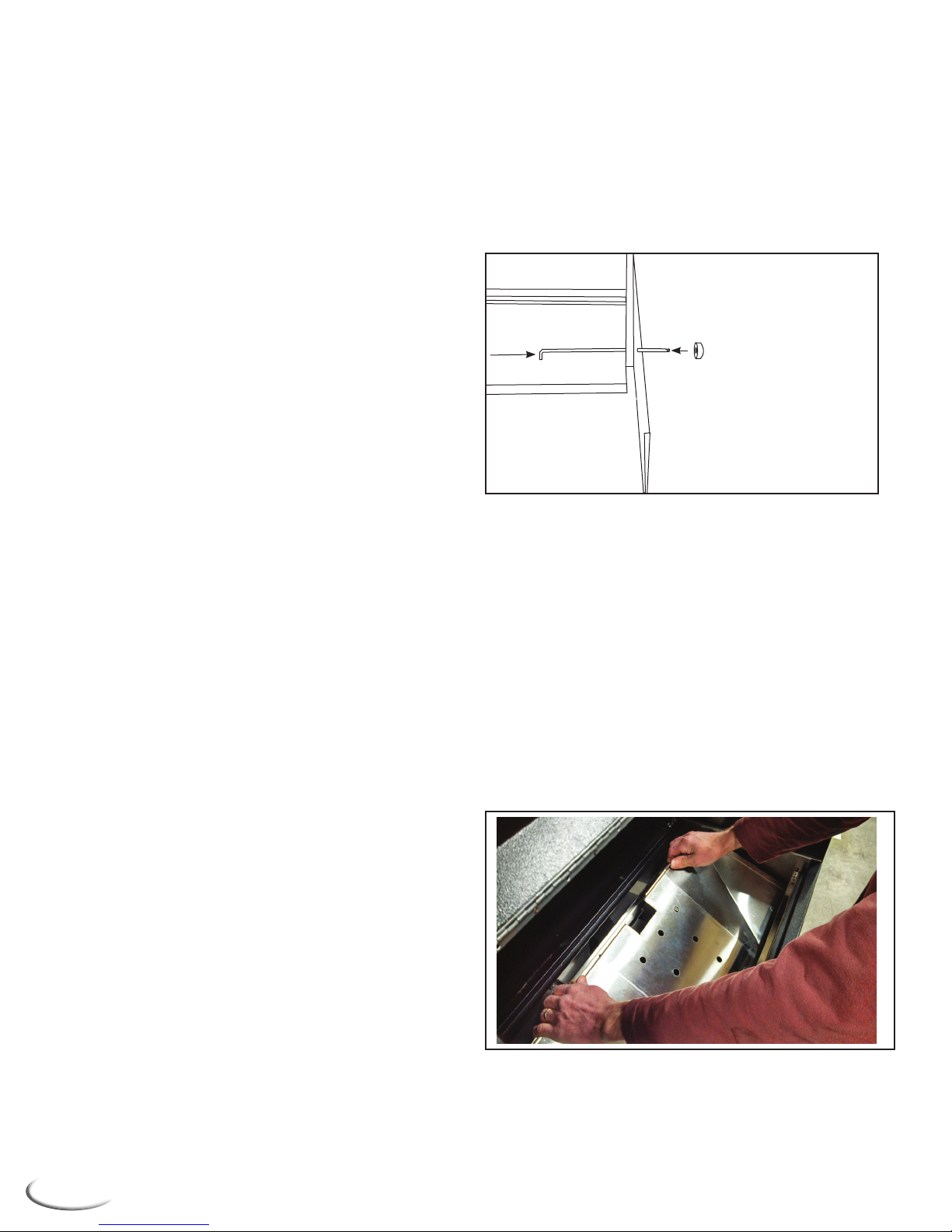
About The Quick Grill Zone Slider
The Quick Grill Zone is used for high temperature
direct grilling and searing over the center grid
of your grill. To use the quick grill zone, simply
slide open the cover by pulling out the handle
located on the right side shelf until it stops. Place
your food on the center of the grill and sear it to
perfection. When grilling on high (480° or FL-3),
the center cooking grid will reach temperatures
over 600°. To close off the quick grill zone and
return to indirect cooking, push the handle back
in until it stops.
About The Adjustable Exhaust Vents
Your grill features adjustable exhaust vents that
can be used to create the perfect cooking envi-
ronment regardless of the weather conditions.
Most of the time you will simply leave both vents
open. On a windy day you can close off one side
of the exhaust to block the wind. On a very cold
day you can partially close both vents to minimize
heat loss. Remember that your grill automati-
cally controls the temperature inside the grill by
adjusting the fuel and combustion air, the adjust-
able vent can simply be used to block excessive
wind or cold weather. CAUTION: Do not touch
the exhaust vents while the grill is running as
they will be extremely hot. If you would like to
adjust the vents while the grill is running, use a
bbq tool or hot mitts.
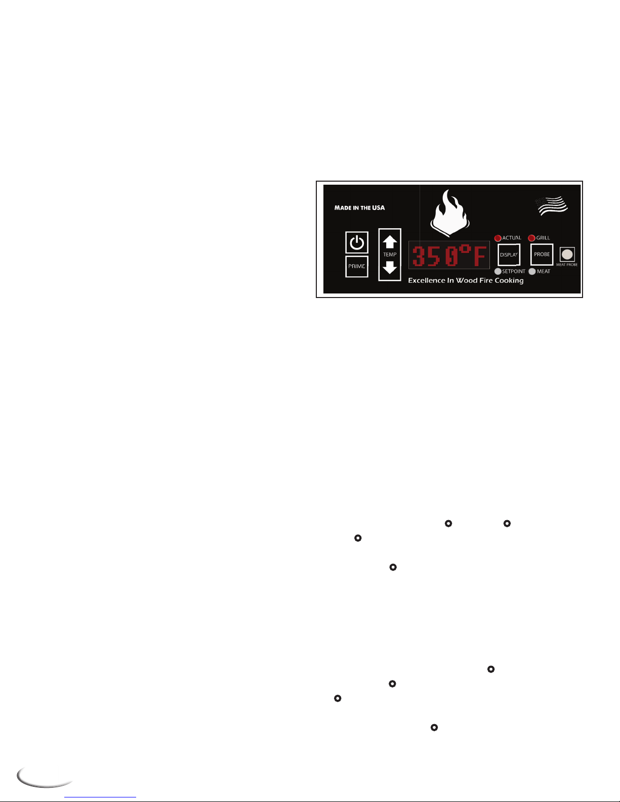
About Your Digital Controls
Your grill automatically controls the temperature,
smoke, and convection with the push of a button.
When you choose an operating temperature of
300° or below, the grill operates in smoke mode.
In smoke mode you will notice the fan “bellowing”
or coming on and off to control both temperature
and smoke. When you choose an operating
temperature above 300°, the grill operates in grill
mode precisely controlling the temperature of
your grill.
1. Power - This powers on and automatically
lights the grill. When you start your grill this
is always the fi rst button that you push. Push
the button again, at any time to shut down the
grill.
2. Prime - This button manually runs the auger
to prime the feed tube and burn pot. Only use
this button if you are starting your grill for the
fi rst time or if you run the grill out of pellets.
(See section 3 for initial seasoning and prim-
ing your grill).
3. TEMP Arrows - Adjusts the set point temper-
ature up or down.
4. PROBE Button - The PROBE Button toggles
the display between ●Grill and ●Meat. When
the ●Grill indicator light is on: you are display-
ing and controlling the temperature of the grill.
When the ●Meat indicator light is on: you are
displaying and controlling the temperature
settings of the meat probe. Note: You must
plug in your meat probe in order to use the
meat probe feature (see “Understanding
The Meat Probe” later in this section).
5. DISPLAY Button - The DISPLAY Button
toggles the display between ●Actual temper-
ature and ●Set point Temperature. When the
●Actual indicator light is on: the grill is dis-
playing the actual temperature of the selected
probe. When the ●Set point indicator light is
on: the grill is displaying the current set point
for the selected probe.

11
6. LED Display - Displays the temperature read-
outs for the grill.
7. Probe Input: Plug in the meat probe when
using the probe feature.
Starting Your Grill
1. Make sure that the hopper is fi lled with hard-
wood cooking pellets and make sure that you
have completed section 3 (initial priming and
seasoning).
2. Make sure your grill is plugged into a GFCI
protected outlet.
3. Push the power button then, using the TEMP
arrows, select any desired cooking tempera-
ture.
4. Your grill will automatically run a lighting se-
quence that will last about 10 minutes. You
will notice that the ●Grill indicator light will
fl ash on the board during the lighting se-
quence. Once the lighting sequence is over
the grill will begin to operate at the tempera-
ture that you have selected.
5. If your grill fails to light and reach a minimum
temperature after 30 minutes, your grill will
automatically shut down and display ER-2
(Failure to light). If this happens, clean out
the burn pot and restart.
Using Your Grill:
Once lit, the grill uses the internal temperature
probe to adjust fuel and fan cycles (bellowing)
allowing the grill to maintain the cooking tem-
perature that you select. If you would like to see
the current temperature inside the grill, simply
push the DISPLAY button. The ●Actual indica-
tor light will be on and the LED display will show
the current temperature inside the grill. Allow the
grill to pre-heat for 15-30 minutes before placing
your food on the grill. You can change the tem-
perature of your grill at any time by pressing up
or down on the temperature arrows. Important:
to maintain your desired cooking tempera-
ture, always use the grill with the lid closed as
much as possible. Opening the lid too often
will waste pellets, reduce temperatures, and
greatly increase your cooking time.
Grilling. ~350°-480+°
Grilling is done over high heat and is the way to
go for backyard staples such as steaks, ham-
burgers and hot dogs. For wood-fi red grilling on
your Grill simply power on your grill and set to
the desired grilling temperature.
Using the quick grilling zone
For high temperature grilling and searing you can
easily slide open the quick grill zone by pulling
out the handle located on the right side shelf until
it stops. Place your food on the center of the grill
and sear it to perfection. When grilling on high
(480° or FL-3), the center cooking grid will reach
temperatures over 600°. To close off the quick
grill zone and return to normal barbecuing, push
the handle back in until it stops.
Manual Cooking Mode:
The grill has 3 manual cooking modes in which
the feed system delivers preset amounts of fuel
to achieve a low, medium and high fl ame. To
use manual cook modes, push up on the TEMP
arrows until the set point is 480°. Continue to
push the up arrow and the display will read FL-1
(low fl ame) FL-2 (medium fl ame) and FL-3 (High
fl ame). Warning: operating the grill in FL-3 for
extended periods of time with the lid closed may
cause the grill to overheat and automatically shut
down. To return to normal operation simply push
down on the TEMP arrow and select a desired
temperature. Pellet grills should usually al-
ways be run with the lid closed to conserve
pellets, but if you would like to cook with the
lid open, these modes provide a consistent
fl ame without using too much fuel.
Barbecuing. ~220°-350°
To BBQ is to cook with indirect heat in a smoky
environment. Roasts, ribs, chicken and various
vegetables are excellent on the Barbecue. Great
BBQ is easy with the Grill. Be sure the Quick Grill
Zone is closed and using the TEMP control pad,
set the your grill to your desired BBQ tempera-
ture. In about 15 minutes the barbecue will be
hot and ready. Load the cooking grids with food,
close the lid and let the Grill do the rest. There’s
no need to tend your food, turning it often, or
worry about it getting burned. That’s the beauty of
indirect cooking. Through convection the wood-
fi re heat is distributed all around the food, sealing
in juices while cooking evenly. When barbecu-

12
ing, leave the lid closed. This will help maintain
a more even temperature, effi cient cook time,
smoky fl avor and save your wood fuel. For larger
items, such as a big roast or whole chicken, use
the meat probe for worry-free barbecuing. Make
sure you insert the meat probe horizontally into
the center of the largest part of meat (e.g. - on
whole chicken- the center of the breast.) Your grill
will turn down to 200° and sound an alarm when
the food is done (see: “Using Your Meat Probe”
below).
Slow Smoking. ~180°-220°
When your temperature is set below 300° the
grill is in Smoke Mode and automatically adjusts
the fuel and combustion air for optimal smok-
ing. Preparation for slow smoking in your grill is
similar to barbecuing. With the Quick Grill Zone
closed, set the controls to your desired tempera-
ture and load the grids with food. Remember
that some smoked foods need a longer cooking
time so be sure to fi ll your pellet hopper before
smoking. When smoking at low temperatures
(below 180°) extreme care should be taken to
ensure bacteria does not grow on food. If you
are unsure about how to properly smoke meats,
only use your grill at low temperatures to smoke
fi sh, nuts etc.
A tip to help achieve your desired level of smoke
fl avor is to combine a slow smoke session with a
grill or barbecue session. You can smoke a whole
chicken at 180° for an hour then finish it off by
barbecuing at 350° until done. You can also bake
in your new pellet grill. It will achieve as consis-
tent a temperature as your kitchen oven, and
makes excellent pizza, calzones and breads. As
a rule, the higher the temperature your grill is set
to the less smoke it will produce. Thus, a pizza
cooked at 425° will have just a hint of brick-oven
smoke fl avor. Desserts like oatmeal raisin cook-
ies and apple pie are uniquely delicious when
prepared in your grill.
Tips For Smoking In Warm Weather
Your new pellet grill is very well insulated which
means you will cook with less fuel and more even
temperatures. This also means that in warmer
weather (70° and above) it can be more diffi -
cult to achieve low temperature smoking (below
200°). Make sure that your exhaust vents are
fully open when low temperature smoking. If you
require lower temperatures in hot weather, you
can prop open the lid of the grill 1-2” to allow ex-
cess heat to bleed off, lowering the temperature
of the grill.
Low and High Temperature Warning
If the grill goes below the minimum operating
temperature, it will re-enter ignition mode and
attempt to relight the grill. If the grill does not
re-light within 30 minutes, the grill will shut down
and display ER--2 (failure to start). If the grill de-
tects temperatures above 600°, it will shut down
and display ER--1 (over temperature error).
If You Run The Grill Out Of Pellets.
Try to always watch the level of fuel in the pellet
hopper so that you do not run the grill out of fuel.
If you do, you will need to re-prime the auger feed
tube just like you did when you lit the grill for the
fi rst time:
1. Fill the hopper with quality hardwood cooking
pellets. Place a small handful of pellets direct-
ly into the burn pot
2. Power on the grill (any temperature setting)
and push the prime button for 2 minutes or
until you hear pellets dropping into the burn
pot.
When to use the meat probe
Using the meat probe allows you to barbecue
your food to an internal temperature that you se-
lect. Use the meat probe when you are cooking
larger cuts of meat such as roasts, whole turkeys,
and brisket. For checking the internal tempera-
ture of smaller cuts like steak, chicken thighs, and
fi sh, we recommend using an instant read hand-
held BBQ thermometer.
Understanding The Meat Probe Func-
tion
When the probe is plugged in and the Probe
Button is set to ●Meat the target temperature for
the meat probe is displayed. The Temperature
arrows can be used to adjust the meat probe set
point between 80° and 200°. Press Display to
see the ●Actual temperature of the meat. Note:
If you adjust the temperature settings, the display

13
will automatically revert to the ●Set point Display
state.
Using your meat probe.
Before setting your probe see the cook time chart
below to determine the minimum safe internal
temperature for different cuts of meat.
Step 1: Insert the meat probe plug into the input
located on the face of the Digital Control Board
Step 2: Insert the probe through the exhaust vent
on the side of the grill and into the thickest part of
your meat.
Step 3: Fire up your grill and set your desired
cooking temperature just as your normally would.
Step 4: Push the PROBE button so that the
●Meat indicator light is on. Select your desired in-
ternal meat temperature by pressing up or down
on the Temperature arrows.
Step 5: Closely monitor your meat’s internal tem-
perature by pushing the DISPLAY button so that
the ●Actual indicator light is on. When the meat
is within 5° internal temperature that you have
set, the grill will automatically turn down to 180°
and the display will read “dOnE”.
If you are going to continue cooking after
your meat is done simply unplug the meat
probe and select your desired temperature
using the temperature arrows.
Thoroughly wash your meat probe with warm
soapy water in between each use.
Meat Temperature Chart
This chart is a guideline for cooking meats to a
safe minimum internal temperature using a food
thermometer. You may prefer to cook your food
more but you should not cook less than these
internal temperatures.
Meat Minimum
Internal
Temperature
Rest Time
Beef, Pork,
Veal & Lamb
Steaks, chops,
roasts
145°F 3 minutes
Ground Beef,
Veal, Lamb,
and Pork
160°F N/A
Meat Minimum
Internal
Temperature
Rest Time
Ham:
Fresh or
smoked (un-
cooked)
145°F 3 minutes
All types and
cuts of poultry
165° N/A
Fish 145° N/A
Recommended Cook Temperatures and
Times
Food Weight/Size Temp/Time
Hamburgers 1/3 lb. 450° -480° for
3-5 mins./side
Pork Chops 1” Thick 400° for 5
min./side
Steaks (rare) 3/4” Thick 480° for 4
min./side
Steaks (me-
dium)
3/4” Thick 480° for 5
min./side
Steaks (well
done)
3/4” Thick 480° for 6-7
min./side
Pork Loin 1.5 lbs. 480° for 20-25
minutes
Whole Chick-
en (180° in
thigh)
3-4 lbs. 325° for 60-70
minutes
Chicken
Breasts
5-8 oz. each 325° for 10-15
mins./side
Using the Hopper StopperTM Quick
Change Pellet System
Step 1: ALWAYS POWER OFF AND UNPLUG
YOUR GRILL BEFORE EMPTYING THE HOP-
PER.
Step 2: Place a bucket on the lower shelf of the
grill underneath the pellet drain tube. The tube
is located directly under the center of the hopper.
Step 3: Open the hopper lid and pull forward and
down on the stopper handle until it comes free.
Pull the stopper entirely out of the hopper. The

14
pellets will now drain into the bucket on the shelf.
If the pellets stop draining, stir them with the stop-
per until they begin to fl ow again.
Step 4: Make sure no pellets or dust remain on
the drain fl ange next to the auger screw. Replace
the stopper by depressing the button and clicking
back into place.
Step 5: Refi ll the hopper with a new fl avor of pel-
lets and you are ready to light your grill.
Section 5- Care and Mainte-
nance
Grill Exterior (every use)
Wipe the exterior of the grill with a warm damp
cloth. Cleaning foreign material off before the unit
is heated will prevent “baked on” grime. Do not
use any abrasive scrubber/cleaner on the black
surfaces of your grill. Grease cutting cleaners or
warm soapy water works well for these surfaces.
Only clean the grill when it is completely cooled.
Be sure to thoroughly remove any cleaner resi-
due with a damp cloth.
Grease Trays (check every use)
Pull out the removable grease drawers located on
the sides of the grill and inspect the aluminum foil
grease trays in the grill. Keep the grease trays
clean or you can simply throw them away and
replace with new ones every few times you use
the grill. (Available at your local dealer or www.
kumastoves.com)
Grilling Grids (every use)
Clean the grids with a long handled BBQ brush
as soon as you are done using the grill. They
clean easily when warm and will be ready to go
for you next time. The grids are also dishwasher
safe. Use caution to avoid burns.
Temperature Sensor (once a month)
There is a temperature sensor (also called an
RTD) located in the left rear of the grilling area.
Keeping this clean allows the digital control to
accurately maintain temperature. When the grill is
cool, gently wipe the sensor with a damp cloth.
Burn pot & Grill Bottom (every 3-5 uses)
With unit completely cool, remove all the grids.
Remove the quick grill zone cover and slide con-
trol rod out of the way. Carefully lift the diffuser
drip tray up and out of the grill. Remove any ash
from the bottom of the grill and the burn pot. Very
important! If you us a shop vac to clean the
burn pot you must be absolutely certain the
ashes are completely cooled before vacuum-
ing. If you have just used the grill, do not use
a shop vac. A tiny ember left to smolder in a
shop-vac could result in a house fi re!
Air Box (once a year)
Make sure that the grill is unplugged and
completely cool before cleaning the air box.
Remove the two screws that secure the burn pot
to the air box. Remove the burn pot from the air
box and set aside being careful not to pull the
ignitor wires attached to the pot. Vacuum out the
air box and reattach the burn pot.
Cover Grill.
Although your grill is constructed from stainless
and aluminized powder coated steel which makes
it weather resistant, it still needs to be protected
from weather. You should always cover your grill
when it is not being used.
Pellet Hopper (extended storage)
If you are going to store your grill for an extended
period of time, we recommend removing the pel-
lets from the hopper and the auger tube. Unplug
your grill before cleaning out the hopper.
Follow the instructions at the end of section 4 to
empty the hopper using the Hopper StopperTM
pellet dump. Close the hopper lid and plug in
your grill. Run the grill on high until the auger is
empty and the grill goes out.

15
Section 6- Troubleshooting
Guide
Use this guide if you are have trouble operating
your grill. For additional help you can contact
your dealer, call Kuma Stoves directly at 888-
714-5294 or send an e-mail to jack@kumas-
toves.com
Error Codes:
If an error is detected, the system will perform the
normal shutdown procedure regardless of the er-
ror value. The system cannot run while an error is
present. If an error has been detected, it can be
cleared by pressing the On / Off button to enter
the Run Mode. However, if the cause of the error
is still present it will enter the Error Mode again.
ER-1 – Over Temperature Error – This error can
be detected at any time, and simply means the
Grill Probe temperature exceeded 600°F. This
can also be a sign of an open connection be-
tween the grill control and the Grill Probe.
ER-2 – Failure to Start Error – Occurs when the
ignition procedure fails to increase the tempera-
ture above 160°F within a 30 minute window.
ER-3 – Power Failure Error – Occurs when the
system is in the Run Mode and power is lost.
When power is reapplied if the system detects
a temperature of less than 160°F, the assump-
tion is that power was lost and the fi re went out
while power was removed. It does not attempt to
re-light the grill in this case. If power is re-applied
before the temperature falls, the system will
return to the last set point and continue the Run
Mode normally.
ER-4 – Grill Probe Short Circuit – Occurs when
the system detects a shorted Grill Probe that can-
not be used to reliably measure temperature
Problem Solution
Grill powers
on but will
not light or
stay lit
• Make sure there are pellets in
the hopper.
• Check for excess ash in the
burn pot
• Without touching, carefully
see if the ignitor is getting hot.
• Make sure the combustion
fan is running.
Grill will not
power on
• Make sure the grill is plugged
in to a working outlet.
• Check the fuse on the back of
the digital control. Replace if
blown.
Grill will not
maintain
correct tem-
perature
• Make sure the combustion
fan is running. (The fan will
“bellow” or run intermittently).
• Check for excess ash in the
burn pot.
• Protect the grill from high
winds and keep the lid closed
as much as possible.
Center grid
gets too hot
or experi-
encing fl are-
ups
• Make sure that the Quick Grill
Zone is fully closed.
• Make sure the diffuser is cor-
rectly installed.
• Clean excess grease from the
diffuser.
Too much
or very thick
smoke
• Check for excess ash in the
burn pot
• Check for wet pellets in the
hopper
Auger is not
running
• During startup and normal op-
eration the auger runs inter-
mittently - this is normal.
• With the grill unplugged,
empty the hopper and check
for any obstruction in the
auger tube.
Section 7- Basic Service, Re-
placement Parts and Accesso-
ries
These are basic guidelines for servicing the
components that make up your grill. Check with
your local dealer for all replacement parts and

16
accessories. Service questions can also be an-
swered by calling the factory at 888-714-5294 or
by contacting your local dealer. To perform any
service to your grill, you must make sure that
the grill is not plugged into an outlet.
Replacing the Digital Control Board.
To perform any service to your grill, you must
make sure that the grill is not plugged into an
outlet.
With an hex key tool, remove the two screws on
the face of the side shelf that attach the control
box to the side shelf. Carefully pull the control
box away from behind the side shelf. With a 5/16
wrench or driver bit, remover the 2 screws on the
bottom of the control box to disassemble the box.
With a hey key tool and 3/8 wrench remove the
screws and nuts that attach the control board to
the control box. Carefully remove the 7 spade
connectors taking note of where each one goes.
Carefully connect the spade connectors to the
new control board. Black wire connects to HOT.
White wire connects to COM. Yellow wire con-
nects to AUG. Blue wire connects to FAN. Red
wire connects to IGN. Brown wires connect to
PROBE 1. Reassemble and reinstall the control
box.
Replace the Digital Control Board Fuse.
To perform any service to your grill, you must
make sure that the grill is not plugged into an
outlet.
To protect the digital control from power surges,
the board is equipped with a 5 amp 250 volt
fuse. To replace the fuse, remove the two screws
underneath the side shelf on the bottom of the
control box. Slide the control box away from the
side shelf exposing the circuit board underneath
the side shelf. Carefully remove the blown fuse
and replace with a new fuse. Reinstall the control
box.
Remove/Replace the Auger and Auger
Motor.
To perform any service to your grill, you must
make sure that the grill is not plugged into an
outlet.
To remove the entire auger assembly, open the
side access panel on the left side of the hopper.
Disconnect the plug labeled “AUG”. Remove the
two screws above and below the auger motor.
The motor with the auger attached will now slide
straight out of the access panel. To remove the
auger motor from the auger assembly, remove
the nut and bolt from the auger sleeve. Reinstall
and reconnect the auger assembly and the auger
connection wire making sure they are clear of the
fan blades.
Remove/Replace the Combustion Fan.
To perform any service to your grill, you must
make sure that the grill is not plugged into an
outlet.
Open the side access panel on the left side of
the hopper. Disconnect the plug labeled “FAN”.
From below the grill, unbolt the fan cage to ex-
pose the combustion fan. Remove the 4 screws
that fasten the fan to the air box. Reinstall the
fan and reconnect the fan wire making sure that
all wires are clear of the fan blades.
Remove/Replace the Ignitor.
To perform any service to your grill, you must
make sure that the grill is not plugged into an
outlet.
Open the side access panel on the left side of
the hopper. Disconnect the plug labeled “IGN”
Remove the 2 screws that fasten the burn pot to
the air box inside the grill. Remove the burn pot
and loosen the ignitor set screw with a hex key
tool. Remove the ignitor from the burn pot and
gently pull the wires through the air box and out
the top of the grill. Thread the new ignitor wires
through the back of the air box and out the small
access hole. Insert the new ignitor into the burn
pot leaving it 1/8” from the end or the ignitor tube.
You will need to align the ignitor bushing with the
set collar before tightening. Tighten the set screw
securing the ignitor in place. Re-install the burn
pot. From the side access panel, connect the new
ignitor to the plug labeled IGN making sure that
all wires are clear of the fan blades.
Remove/Replace the RTD (Temperature
Sensor)
To perform any service to your grill, you must
make sure that the grill is not plugged into an
outlet.
Open the side access panel on the left side of
the hopper. Find and disconnect the plug labeled

17
“RTD”. With a pair of wire cutters, cut the plug
housing off of the RTD lead wires. DO NOT CUT
THE PLUG HOUSING OFF OF THE OTHER
SIDE (HARNESS SIDE) OF THE PLUG. From
inside the grill at the back right, remove the
screws that fasten the RTD to the grill. Remove
the RTD pulling the lead wire through the small
hole in the back of the grill. Slip the lead wires
for your new RTD down through the center hole
between the 2 screw holes then through the hole
in the back of the grill. You can reach up from
underneath the hopper to guide the wires above
the fan air box over to the left side access panel.
Insert the 2 lead wires to the new plug housing
(you will hear a click when they are in place). It
does not matter which way the wires are con-
nected. Give them a little tug to make sure they
are secure in the housing. Plug the RTD back
into the plug labeled “RTD”. Fasten the new RTD
to the grill using the same 2 screws.
Section 8- Warranty Information
Your grill manufactured by Kuma Stoves Inc. has
a 5 year limited warranty effective from the date
of purchase by the original owner against de-
fects in material and workmanship. All electronic
components have a 3 year replacement warranty.
The limited warranty does not apply to the meat
probe, burn pot, or cooking grids.
Warranty Coverage:
To ensure warranty coverage, it is very important
that you save your proof of purchase and register
your warranty within 30 days of purchase at ku-
mastoves.com or fi ll out and return the warranty
registration in your owners packet. This warranty
covers your new grill from defects in materials
and workmanship for the period outlined in this
warranty. Kuma Stoves reserves the right to
replace, repair or authorize repair of any defec-
tive part at its sole discretion. This warranty is not
transferable and covers only the original owner
of the product from the time of purchase. All parts
that have been replaced under this warranty will
have 90 day warranty coverage. The maximum
value of this warranty is the original purchase
price of the product. This warranty is subject to
the conditions and limitations outlined in this sec-
tion.
Warranty instructions:
For your warranty claim, please contact the deal-
er where you purchased your grill. You may also
contact Kuma Stoves directly at 888-714-5294
or contact us online at kumastoves.com. When
making warranty inquiries please have your proof
of purchase and model name. Also, please re-
member that shipping and handling costs are not
covered under this warranty.
Warranty exclusions:
Due to variables beyond the manufactures’ con-
trol, no implied or written performance guarantee
or warranty is given for the unit or food product.
This warranty does not cover: 1. The formation
of rust- except in the case of structural damage
within the fi ve year period. 2. The fi nish of any
surface on the unit. 3. Any unit used in a com-
mercial or nonresidential application. 4. Damage
caused from: power surges, unauthorized modi-
fi cations, using incorrect fuel and/or accelerants,
shipping/handling, failing to follow the manufac-
turer’s assembly/installation instructions. 5. Dam-
ages due to ordinary wear and tear. 6. Damages
due to a failure of the customer to provide normal
maintenance and care for the unit. 7. Damages
due to natural disaster or natural elements. 8.
Wear characteristics typical of the materials that
are used. 9. Damages to any product not manu-
factured by Kuma Stoves. 10. Shipping costs as-
sociated with replacement parts. Please talk with
an authorized dealer about the potential charges
for shipping.
Table of contents
Other Kuma Stoves Grill manuals
Popular Grill manuals by other brands

Weber
Weber Q 3600 installation guide

Campingaz
Campingaz Classic LX 2 Series Assembly instructions

Lang
Lang PaneBella Fresco PBF12G Installation and operation instructions

Onward
Onward Broil King 9572-44 Assembly manual & parts list

Enders
Enders KANSAS PRO 4 SIK PROFI TURBO instruction manual

Matador
Matador Supernova 4 user manual