Kuman DT132F Assembly instructions
OPERATOR’S
INSTRUCTION
MANUAL
DIGITAL MULTIMETER
READ AND UNDERSTAND THIS MANUAL
BEFORE USING THE INSTRUMENT.
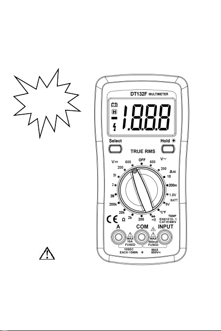
WARNING
MODEL:
DT132F
CE CAT III 600V
TRUE- RMS
BACK
LIGHT

-2-
Warning
To avoid possible electric shock or personal injury, and
to avoid possible damage to the Meter or to the equipment
under test, adhere to the following rules:
Before using the Meter inspect the case. Do not use
the Meter if it is damaged or the case (or part of the
case) is removed. Look for cracks or missing
plastic. Pay attention to the insulation around the
connectors.
Inspect the test leads for damaged insulation or
exposed metal. Check the test leads for continuity.
Do not apply more than the rated voltage, as marked
on the Meter, between the terminals or between any
terminal and grounding.
The rotary switch should be placed in the right
position and no any changeover of range shall be
made during measurement is conducted to prevent
damage of the Meter.
When the Meter working at an effective voltage over
60V in DC or 30V rms in AC, special care should be
taken for there is danger of electric shock.
Use the proper terminals, function, and range for
your measurements.
Do not use or store the Meter in an environment of
high temperature, humidity, explosive, inflammable
and strong magnetic field. The performance of the
Meter may deteriorate after dampened.
When using the test leads, keep your fingers behind
the finger guards.
Disconnect circuit power and discharge all
high-voltage capacitors before testing resistance,
continuity, diodes.
Replace the battery as soon as the battery indicator
appears. With a low battery, the Meter might
produce false readings that can lead to electric shock
and personal injury.
Remove the connection between the testing leads
and the circuit being tested, and turn the Meter power

-3-
off before opening the Meter case.
When servicing the Meter, use only the same model
number or identical electrical specifications
replacement parts.
The internal circuit of the Meter shall not be altered at
will to avoid damage of the Meter and any accident.
Soft cloth and mild detergent should be used to clean
the surface of the Meter when servicing. No abrasive
and solvent should be used to prevent the surface of
the Meter from corrosion, damage and accident.
The Meter is suitable for indoor use.
Turn the Meter power off when it is not in use and
take out the battery when not using for a long time.
Constantly check the battery as it may leak when it
has been using for some time, replace the battery as
soon as leaking appears. A leaking battery will
damage the Meter.
1. General Specifications
Display : LCD, 3999 counts updates 2/sec
LCD Size : 55 x 31mm
Polarity Indication : “-” displayed automatically
Over-range Indication : “OL” displayed
Low Battery Indication : “ ” displayed
Range select : auto or manual
Operation Temperature : 0°C to 40°C, less than 80%RH
Storage Temperature : -10°C to 50°C, less than 85%RH
Battery Type : 1.5V x 3, AAA size
Dimension (H×W×D) : 145×70×35mm
Weight : Approx 157g
2. ELECTRICAL SYMBOLS
DC (Direct Current).
AC (Alternating Current).
DC or AC
Important safety information.
Refer to the manual.
Dangerous voltage maybe present.
-4-
Earth ground.
Low battery
Fuse.
Diode
Continuity test
°C
Centigrade
°F
Fahrenheit
Conforms to European Union directive.
Double insulated.
APO auto power off
data hold
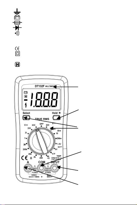
LCD
RANGE
switch
10A jack
VΩmA jack
COM jack
Back Light
Button
Hold
Button
-5-
Technical Specifications
Accuracies are guaranteed for 1 year, 23ºC±5ºC, less
than 80%RH
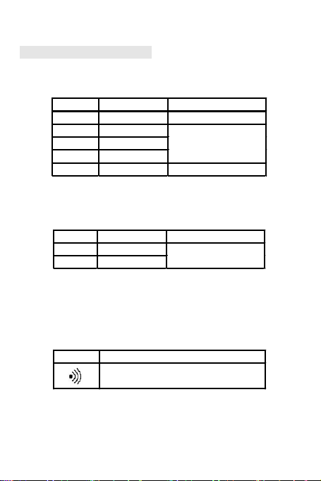
DC VOLTAGE
RANGE RESOLUTION ACCURACY
200mV 100uV ±(0.5% of rdg + 3D)
2000mV 1mV
20V 10mV
200V 100mV
500V 1V ±(1.0% of rdg + 5D)
±(0.8% of rdg + 5D)
OVERLOAD PROTECTION: 220V rms AC for 200mV
range and 600V DC or 600V rms for all ranges.
AC VOLTAGE
RANGE RESOLUTION ACCURACY
200V 100mV
500V 1V
±(2.0% of rdg +10D)
RESPONSE: Average responding, calibrated in rms of a
sine wave.
FREQUENCY RANGE: 45Hz ~ 450Hz
OVERLOAD PROTECTION: 600V DC or 600V rms for
all ranges.
AUDIBLE CONTINUITY
RANGE DESCRIPTION
Built-in buzzer sounds if resistance
is less then 30±20Ω
OVERLOAD PROTECTION: 15 second maxi- mum 220
V rms.

-6-
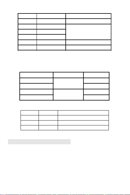
DC CURRENT
RANGE RESOLUTION ACCURACY
200uA 100nA
2000uA 1uA
20mA 10uA
200mA 100uA ±(2.0% of rdg +2D)
10A 10mA ±(2.0% of rdg +10D)
±(1.8% of rdg +2D)
OVERLOAD PROTECTION: 500mA/250V fuse (10A
range unfused).
MEASURING VOLTAGE DROP: 200mV
AC CURRENT
Range
Resolution
Accuracy
200µA
0.1µA
±(1.5% of rdg + 8dgts)
2000µA
1µA
20mA
10µA
200mA
100µA
2A
1mA
±(2.0% of rdg + 4dgts)
10A
10mA
Overload Protection:
µA and mA ranges: F0.5A/600V fuse
4A and 10A ranges: F10A/600V fuse
Max. Input Current:
“INPUT” jack: 200mA
“A” jack: 10A
(For measurements>5A: duration <10 seconds,
interval >15 minutes)
Voltage Drop: 400µA, 40mA and 4A ranges: 20mV
4000µA, 400mA and 10A ranges: 200mV
Frequency Range: 40Hz ~ 400Hz
Response: Average, calibrated in rms of sine wave
-7-
RESISTANCE
RANGE RESOLUTION ACCURACY
200Ω 0.1Ω ±(1.0% of rdg +10D)
2000Ω 1Ω
20KΩ 10Ω
200KΩ 100Ω
20MΩ 10KΩ ±(1.0% of rdg +10D)
200MΩ 100KΩ ±[5%*(rdg-10) + 10dgts)
±(1.0% of rdg +4D)
MAXIMUM OPEN CIRCUIT VOLTAGE: 3V.
OVERLOAD PROTECTION: 15 seconds maxi- mum
220Vrms.
TEMPERATURE (with K-TYPE PROBE)
RANGE RESOLUTION ACCURACY
-40ºC~150ºC ±(1.0% + 4)
150ºC~1370ºC ±(1.5% + 15)
-40ºF~302ºF ±(1.0% + 4)
302ºF~1999ºF ±(1.5% + 15)
1ºC
1ºF
BATTERY TEST (DT33B only)
Range
Resol.
Internal Resistance
12V
10mV
1.2KΩ
9V
10mV
900Ω
1.5V
1mV
3KΩ
OPERATING INSTRUCTIONS
DC & AC VOLTAGE MEASUREMENT
1. Connect red test lead to “INPUT” jack, Black lead to
“COM” jack.
2. Set RANGE switch to desired VOLTAGE range, if the
voltage to be measured is not known beforehand, set
switch to the highest range and reduce it until
satisfactory reading is obtained.

-8-
3. Connect test leads to device or circuit being
measured.
4. Turn on power of the device or circuit being
measured voltage value will appear on Digital
Display along with the voltage polarity.
DC CURRENT MEASUREMENT
1. Red lead to “INPUT”. Black lead to “COM” (for
measurements between 200mA and 10A connect red
lead to “10A” jack with fully depressed.)
2. RANGE switch to desired DCA range.
3. Open the circuit to be measured, and connect test
leads INSERIES with the load in with current is to
measure.
4. Read current value on Digital Display.
5. Additionally, “10A” function is designed for
intermittent use only. Maximum contact time of the
test leads with the circuit is 15 seconds, with a
minimum intermission time of seconds between
tests.
RESISTANCE MEASUREMENT
1. Red lead to “INPUT”. Black lead to “COM”.
2. RANGE switch to desired Ω range.
3. If the resistance being measured is connected to a
circuit, turn off power and discharge all capacitors
before measurement.
4. Connect test leads to circuit being measured.
5. Read resistance value on Digital Display.

-9-
DIODE MEASUREMENT
1. Red lead to “INPUT”, Black lead to “COM”.
2. RANGE switch to “ ” range.
3. Connect the red test lead to the anode of the diode to
be measured and black test lead to cathode.
4. The forward voltage drop in mV will be displayed. If
the diode is reversed, figure “1” will be shown.
TEMPERATURE MEASUREMENT
1. RANGE switch to ºC or ºF range, it will display room
temperature in ºC or ºF value.
2. Connect the K-type thermoelectric couple to “INPUT”
and “COM” jacks.
3. The display will read Temperature value ºC or ºF.
NOTE: The TP-01 K-type thermocouple Max. Operating
temperature of Probe: 250˚C/482˚F (300˚C/572˚F
short-term). The sensor supplied with the instrument is
an ultra fast response naked bead thermocouple
suitable for many general purpose applications.
AUDIBLE CONTINUITY TEST
1. Red lead to “INPUT”, Black lead to “COM”.
2. RANGE switch to “ ” range.
3. Connect test leads to two points of circuit to be
tested. If the resistance is lower then 30Ω±20Ω, the
buzzer will sound.
BATTERY TEST
1. Connect the black test lead to the "COM" jack and
the red test lead to the " INPUT " jack (Note: The
polarity of the red test lead is positive "+").
2. According to the different type of the battery (1.5V,

-10 -
9V,) to be tested, set the range switch to the desired
BATT range.
3. Connect the test leads to the battery to be tested.
4. Read the reading on the display. The polarity of the
red test lead connection will be indicated.
Table of contents
Popular Multimeter manuals by other brands


Gossen MetraWatt
Gossen MetraWatt METRAmax 6 operating instructions

PeakTech
PeakTech 4000 Procedure of calibration

YOKOGAWA
YOKOGAWA 90050B user manual

Gossen MetraWatt
Gossen MetraWatt METRALINE DMM16 operating instructions

Fluke
Fluke 8846A Programmer's manual

Tempo Communications
Tempo Communications MM200 instruction manual


