Unit UT8806E User manual

Instruments.uni-trend.com 1/ 13
Quick Guide
UT8806E Desktop Digital Multimeter

Quick Guide UT8806E Desktop Digital Multimeter
Instruments.uni-trend.com 2/ 13
Copyright
Copyright is owned by Uni-Trend Technology (China) Co., Ltd.
Trademark
UNI-T is the registered trademark of Uni Trend Technology (China) Co., Ltd.
File Version
UT8806E20230801-V1.00
Statement
UNI-T products are protected by patent rights in China and foreign countries, including issued and
pending patents.
UNI-T reserves the rights to any product specification and pricing changes.
UNI-T reserves all rights. Licensed software products are properties of Uni-Trend and its subsidiaries
or suppliers, which are protected by national copyright laws and international treaty provisions.
Information in this manual supersedes all previously published versions.

Quick Guide UT8806E Desktop Digital Multimeter
Instruments.uni-trend.com 3/ 13
1. General Safety Summary
The instrument is designed to meet the safety requirements of GB4793 safety requirements for
electronic measuring instruments, IEC/EN61010-1, EN61010-2-030 pollution class 2, overvoltage CATI
1000V, CATII 300V and double Insulation; and complies with the IP65 standard for waterproofing and
dustproofing.
This manual contains information and warnings that must be observed to keep the instrument in a safe
condition and ensure safe operation.
1. Use Proper Power Cord. Use only the power cord specified for this product and certified for the country
of use, and make sure that no metal parts are exposed and the insulation is broken.
2. Ground the Product. This product is grounded through the grounding conductor of the power cord. To
avoid electric shock, the grounding conductor must be connected to earth ground. Before making
connections to the input or output terminals of the product, ensure that the product is properly
grounded. The signal ground on the rear panel of the product is the same as the ground potential.
3. Check the Wire. Check if the insulation of the test lead is damaged or if the lead is exposed; check if the
test lead is on, if there is any damage to the lead, replace it before using the instrument.
4. Observe All Terminal Ratings. The voltage applied between the terminals or any one of the terminals and
the grounding point must not exceed the rated value indicated on the instrument.
5. Do Not Touch Live Part. Do not touch exposed connection wires, unused inputs or circuits being
measured while the instrument is in use. When measuring voltages higher than 60V DC or 30V AC, be
sure to exercise caution and remember to keep your fingers away from the meter's guard position to
prevent electric shock.
6. Do Not Operate with Suspected Failures. If you suspect that this product is malfunctioning, contact UNI-
T's authorized service personnel for testing. Any maintenance, adjustment, or replacement of parts on
this product must be performed by UNI-T authorized service personnel.
7. Avoid Exposed Circuitry. Do not touch exposed connections and components when power is present.
8. Do Not Operate Without Covers. Do not operate this product with covers or panels removed, and do not
adjust the internal circuit.
9. Use Proper Fuse. Use only the fuse type and rating specified for this product.
10. Use Proper Over-voltage Protection. Make sure that no overvoltage (e.g. caused by lightning) reaches the
product, as this may result in electric shock to the operator.
11. Avoid Severe Environment. Avoid using the instrument in high temperature, high humidity, flammable,
explosive and strong electromagnetic environments.
12. Disconnect the Power Supply. Before testing the impedance, conduction, diodes, or capacitance,
disconnect power and discharge all high voltage capacitors.
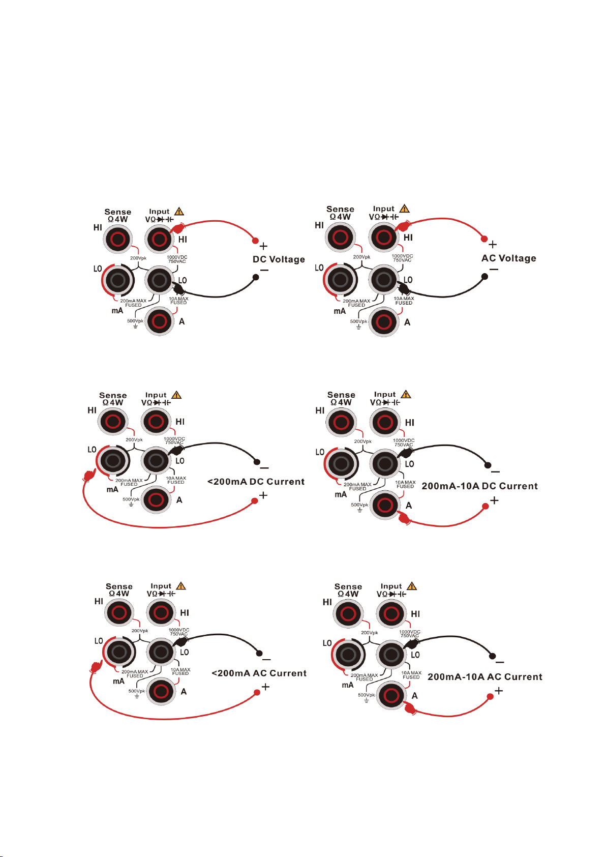
Input Terminal Protection Limit
1. Main Input Terminal (HI and LO)
HI and LO input terminals are used for voltage, impedance, capacitance, continuity, frequency and diode
test measurements. These two terminals define the following two protection limits.
1) Protection limit from HI to LO, which is 1000 VDC or 750 VAC. This is also the maximum voltage that
can be measured. This limit can also be expressed as a maximum of 1000 Vpk.

Quick Guide UT8806E Desktop Digital Multimeter
Instruments.uni-trend.com 4/ 13
2) Protection limit from LO to ground. The LO input terminal can be safely "floated" to a maximum of
500 Vpk with respect to ground. The protective limit of the HI terminal is a maximum of 1000 Vpk
with respect to ground. Therefore, the sum of the "floating" voltage and the measured voltage must
not exceed 1000 Vpk.
2. Sampling Terminal (HI sense and LO sense)
HI Sense and LO Sense terminals are used for four-wire impedance test and measurement. These two
terminals define the following two protection limits.
1) Protection limit from HI Sense to LO Sense. Protection limit of HI Sense and LO Sense are 200 Vpk.
2) Protection limit from LO Sense to LO. Protection limit of LO Sense and LO are 2 Vpk.
3. Current Input Terminal (mA and A)
1) The mA and LO terminal are used to measure the current test below 200mA. The rear panel fuse
provides a maximum protection limit of 250mA for current flowing through the mA terminal.
2) The Aand LO terminal are used to measure the current test from 200mA to 10A. The rear panel fuse
provides a maximum protection limit of 10A for current flowing through the Aterminal.
Notes
The voltage at the current input terminal is about the same as the voltage at the LO terminal. To maintain
good protection, this fuse can only replace with a fuse of the specified type and rating.
IEC Measurement Category II Overvoltage Protection
To avoid the risk of electric shock, the UT8806E digital multimeter provides overvoltage protection for
electric mains connections that meet both of the following conditions.
1. The HI and LO input terminals are connected to the electric mains under Measurement Category II
conditions (described below).
2. The maximum line voltage of the electric mains is 300 VAC.
Warnings
IEC measurement category II includes electrical installations connected to the mains via a socket on a branch
circuit. These devices include most small appliances, test equipment, and other devices plugged into branch
circuit sockets.
Measurement of UT8806E Digital Multimeter
The HI and LO input terminals are connected to the electric mains (up to 300VAC) in these devices, or to
branch circuit socket. However, the HI and LO input terminals of the UT8806E cannot be connected to the
electric mains in permanently installed electrical devices, such as main breaker panels, sub-panel breakout
boxes, or permanently wired motors. These devices and circuits are susceptible to overvoltage that exceed
the protection limits of the UT8806E.
Notes
The voltage above 300VAC can only be measured in circuits that disconnected from the electric mains.
However, transient overvoltage also exist in circuits when disconnected from the electric mains, and the
UT8806E can safely withstand incidental transient overvoltage up to 2500 Vpk.
Do not use this device to measure circuits where transient overvoltage may exceed this level.

Quick Guide UT8806E Desktop Digital Multimeter
Instruments.uni-trend.com 5/ 13
2. Quick Guide
This chapter is to introduce the preparation of the UT8806E digital multimeter and simply introduce the
front/rear panel and display screen.
2.1 General Inspection
Before you use a new UT8806E multimeter, it is recommended that you check the instrument as follows.
(1) Check for damage caused by transportation
If you find that the packing carton or protective foam cushion is badly damaged, keep it until the
complete unit and accessories have passed the electrical and mechanical tests.
(2) Checking accessories
If you find that an accessory is missing or damaged, contact the UNI-T distributor responsible for your
business or the local UNI-T office.
(3) Checking the complete unit
If you find that the instrument is visually damaged, that the instrument is not working properly, or that it
fails a performance test, contact the UNI-T distributor responsible for the operation or the local UNI-T
office.
If the instrument is damaged due to transportation, please retain the packaging. Notify the shipping
department and the UNI-T distributor. UNI-T will arrange for repair or replacement.
2.2 Before Use
To perform a quick verification of the instrument’s normal operations, please follow the steps below.
(1) Connect to the Power Supply
The power supply voltage range is from 100 VAC to 240 VAC, the frequency range is 45 Hz to 440 Hz. Connect
the multimeter to the power supply line that equipped with the product or any power supply line that meets
the local country standards. When the multimeter is connected to the invalid power supply, the indicator of
the power soft switch button at the lower left cornerof the front panel will not be lit, and the soft switch
button has no effect at this time; when the multimeter is correctly connected to the valid power supply, the
indicator of the power soft switch button at the lower left corner of the front panel of the multimeter will be
red, and the multimeter can be turned on by pressing the soft switch button at this time.
(2) Boot Check
Press the soft power button and the light should change from red to green, and UNI-T will display on
the screen. The multimeter will show a boot animation, and then enter the normal interface.
Warning: To avoid electric shock when using the probe to measure high voltage, please ensure that the probe
insulation is in good condition and avoid physical contact with any metallic part of the probe.

Quick Guide UT8806E Desktop Digital Multimeter
Instruments.uni-trend.com 6/ 13
3. Adjusting Handle
The multimeter’s handle can adjust to three positions by appropriate strengths, as shown in Figure 1-1, 1-2
and 1-3.
Figure 1-1 Adjusting Handle
Figure 1-2 Holding Down Position Figure 1-3 Moving Position

Quick Guide UT8806E Desktop Digital Multimeter
Instruments.uni-trend.com 7/ 13
4. Front Panel
The UT8806E digital multimeter provides the user with a simple and clear front panel. These controls are
displayed in logical groupings, and basic operations can be performed by simply selecting the appropriate
button, as shown in Figure 1.
Figure 1 Front Panel
Note: To learn more about the front panel, refer to Chapter 1, Front panel of the user's manual.
2:USB Host 6:Range and
3:Power Button 7:Signal
4:Menu Operation Key 8:Front/rear Input
1:LCD 5:Measurement and Auxiliary Function Key
1
2
3
4
5
6
7
8

Quick Guide UT8806E Desktop Digital Multimeter
Instruments.uni-trend.com 8/ 13
5. Rear Panel
The rear panel of the UT8806E digital multimeter provides multiple ports, including USB Device, RS-232C,
LAN and GPIB (option) as shown in Figure 3.
Figure 2 Rear Panel
Note: To learn more about the front panel, refer to Chapter 1, Rear panel of the user's manual.
1:Power Input Port
2:RS-232 Communication Port
3:RJ45 Internet Communication Port
4:USB-DEVICE Port
5:GPIB Port
6:VMC Signal Output Port
7:Ext TRIG Signal Input Port
8:Signal Input
9:Lock Hole
10:Ground Terminal
9
8
7
6
4
5
2
10
3
1

Quick Guide UT8806E Desktop Digital Multimeter
Instruments.uni-trend.com 9/ 13
6. User Interface
Figure 3 Display Menu
Measuring Range
Trigger Mode
Measurement
Function
Reading Display
Unit
Operation Menu

Instruments.uni-trend.com 10 / 13
7. Measurement Connection
This multimeter provides various measurement functions. After selecting the desired measurement function,
connect the signal (device) under test to the multimeter as shown in the following figure.
DC Voltage Measurement AC Voltage Measurement
DC <200mA Current Measurement DC 200mA-10A Current Measurement
AC <200mA Current Measurement AC 200mA-10A Current Measurement
2-wire Resistance Measurement 4-wire Resistance Measurement

Quick Guide UT8806E Desktop Digital Multimeter
Instruments.uni-trend.com 11 / 13
Capacitance Measurement Frequency/Period Measurement
Continuity Measurement Diode Measurement
Temperature Measurement

Quick Guide UT8806E Desktop Digital Multimeter
Instruments.uni-trend.com 12 / 13
8. Built-in Help
If you need to get the built-in help information of this product, press [Shift] + [Acquire] to enter the help
system at first, then press the arrow keys to select the desired help item, and finally press [OK] to view the
corresponding help information.
1. Basic Measurement
2. Temperature Measurement
3. Capacitance Measurement
4. Mathematical Operation
5. Dual Display
6. Storage Function
9. Troubleshooting
The following is a list of malfunctions and troubleshooting methods that may occur during the use of the
digital multimeter. When you encounter these faults, please follow the appropriate steps to deal with them,
if the problem cannot be fixed, please contact UNIT for assistance.
1. If the multimeter remains black without any display when the power switch is pressed.
(1) Check if the power plug is properly connected.
(2) Check if the power switch on the rear panel is turned on.
(3) Check if the fuse of the power input on the rear panel is fusing. If it is fusing, replace the fuse as
required (250mA/250V, slow-blow fuse).
(4) After making the above checks, restart the instrument.
(5) If the product still does not work properly, contact the UNI-T Service Center for assistance.
2. When connect a current signal, no change in reading.
(1) Check if the probe is properly inserted into the current jack and LO jack.
(2) Check if the current fuse on the rear panel probe is fusing.
(3) Check if the measurement scale is correctly switched to DCI or ACI.
(4) Check if the input is ACI but the scale is in DCI.
3. When a DC power signal is connected, the reading display is not normal.
(1) Check if the probe is correctly inserted into the current jack and LO jack.
(2) Check if the current fuse on the rear panel probe is fusing.
(3) Check if the measurement scale is correctly switched to DCI or DCV.
(4) Check if the input is DCI but the scale is in ACI.
4. USB cannot be recognized.
(1) Check if the USB can work normally.
(2) Make sure the USB is USB Flash, this instrument does not support hard disk type USB.
(3) Make sure the capacity of the USB is too large, the multimeter recommends using a USB not more
than 128GB.
(4) After restarting the instrument, insert the USB again for checking.
(5) If the USB still does not work properly, contact the UNI-T Service Center for assistance.

Quick Guide UT8806E Desktop Digital Multimeter
Instruments.uni-trend.com 13 / 13
10.Appendix Contact Us
If the use of this product has caused any inconvenience, if you in mainland China you can contact UNI-T
company directly.
Service support: 8am to 5.30pm (UTC+8), Monday to Friday or via email.
Email address: fosh@uni-trend.com.cn
For product support outside mainland China, please contact your local UNI-T distributor or sales center.
Many UNI-T products have the option of extending the warranty and calibration period, please contact your
local UNI-T dealer or sales center.
To obtain the address list of our service centers, please visit our website at URL: http://www.uni-trend.com
Other manuals for UT8806E
2
Table of contents
Other Unit Multimeter manuals