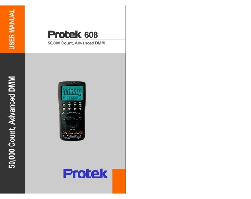
PRO-TEK 608 User manual

608
50000
Count
Digital
Multimeter
Protei<


TABU!
OF
CONTENTS
1-1.
MAIN
FEATURES
4
._-_._,_
.
._
--
-_
.
__
..
_--
._
.......
1
.
~
FRO~.T.P.ANEL
OESCI1I~!I!!I(lCO
.
KEY.ROTARY.SOClEI)
5
1-3.
REAR
PANEL
OESCRIPlION(RS232C.TlU·STANO.BATTERy)
I
tMODJ.!!fY
Ol'.ERAflD
L ____.
______
.____
J
LI!PE~I1.!lL
___
..
___
..
_ H
PO
W.!11
_
0
!li~
.
____
.
_________
I
_.
H
OCmV
.
OCY
I
._._
._
..
._._
...
_...
....
•
...
_ .•
...•...
.. .
__
......
.
__
.__..
!:
.3
c
AC
mY,.A.
CY
.
AC
+
OC
mV
.A
C+
OCV
II
--_._----
3·4.
DCuA.OCmA.DCA
1•
. 3·
5.
ACuA.ACmA
.
ACA
.
AC
+
OCuA
.A
C+.O_
CmA.Ai:.
.
:+:
.
OEA
__
l_l .
_.
__
._
..
_.
____
.
_____
•
__
._
.l
.
c!c
_
ohm.
CONTlN
.U!l!!I'.hm
11
3·7.
nS
12
-------_
._
._._
-_
..
_--_.
____
__
._
...
•._
.•..
.
_.
__
..
.•
...
_._
.....
_
...
•
...
_ . .l,8.J!,N_
ER
_
ol!'f1
._
E_
..
.
__
_
12
H
CAPAC1TANCE
13
---_._
..
_-----------
3·10
.
Hz
14
--_
._
-_
. 14
15
3·11.P
ULSE
WIDTH
=~
--~~~---=-
3
..c
12
.
TEMPERATURE
4"llt2.~lC
INU~JA!;L
_
.....
___
~
·1.
CONNECTIO
N
BETWEE
N
PC
&
METER
11
4-2.
RS232C
CABLE
&
PIN
CONNECTION
1i
4·3.C
OMMUNICATlON
SPEC.
1i• • • H
•••
_._._
••
___
..
__
..
_.
___
•
__
•
____________
___
•
_______
_
4
...
INSTAllATION
11
4·5.
OPERATION
11
~.
SPECI.~L
FU.!l.I;!IDN
D~~.~IPT.!I!
!L
.
~
.
~
.,
AUm~F.F
__
.
_____
._
.___.._...
___
..
__
.
•.
_
..
_'_I_
..
__
..::.
5.2
_.L_
OW
_B_
ATT
_ E_
RY
_I_
NO
.
ICATlON
11
5·
3.
BAR
GRAPH
DISPLAY
11
-_
......
_--_
._-
------_._._-
----_._---
-
--_._---,
_._
..
_
......
_._._
..
_____
._
..
__
.
____
..._
..
5
:!.!o!_~.
I'!
..
.
.....
_
....
_
...
_.
___
._
•..•..•.
__
!!...
5·5
. ±
PEAK
11
5·6.
AVERAG
E
-..
--.---
.
---.-
~~"'--
-
5·).
GOiNG
II
..
__
....
.-
II
21
5·B.
STORE
5·9.
RECAU
21
iCM
AINTENANCI
-------
-
&:"I-:--G
-
EN
-
ERAl
-··-··--
..
--
..
---·--
..
·
·-··
..
-·-·---
ZI-·
.
__
.
__
.
6·2.
BATTERY
REPLACEMENT
21
_
.H
..
.
__
...
_
...
_
__
_
___
___
__
....
__
.
____
_ __
...
_
__
_
..
__
__
.H
..
...
__ .
__
..
_
....
..
__
._._
..
•
___
•_
___
..._
.....
___
__
_.
...
__
•_ _.
____
..__
..
_"
_H.
__
_
6
·3.
FUSE
REPLAC
EM
EN)
ZZ
._--
--
--
-_
._----
-_.
__
._------------------_._---_._---
H
CAlI8RATIO
N
23
2)
7-2
.
ElECTRICAL
SP
E
CIFICATI
",
ON
,==
__
.
)·3.
RANGE
SWITCHING
BY
FUNCTIONS
33
_
••
___
••
H.
__
_ . .
.......
____
•••
_._
.
___
...............
_ . . . .
..
__
._'"
.
__
•
____
•
____
.~
___
• •
_._
......
__
._.
__
.
_._._
7-4
.
MODE
SElECTION
BY
fU
NCT
IONS
34
------
.-.-------
...
-
...
-
......
----
....
-
.---
.~
--.-.-------._.
__
._
-_
..
_.._
..
_._
._-_._._-
)·5.
SPECIAL
SYMBOLS
ON
LCD
15
)·6.
lCo
STAT
US
BY
FUNCTIONS
11
... _....-
...•
_._
...
-
._
...
_._.
__
._
......
-
~--
...
-.-
.
--
.-
.----
-.-.---
..
.-
..
-
..
-
--
..
-.
H
LCD
STATUS
BY
M
ODES
3)
)·B
.
ASSEMBLY
DIAG
"R"A
",
M
,-
______
_
)·9.
SAFETY
.
)·
10
.
REPLACEMENT
PARTS
LIST
11
4Z

IN11IODUCT1ON
4
o INTRODUCTION
I-I.
MAIN
FEATURES
1)
0.05%
basic accuracy, 50,000 count resolution with
SOms
sampling time
featuring 4th order delta-sigma analog to digital conversion and a var-
iety
of
useful functions
makes
the
608
by
far
the
best
hand·held
DMM
available today.
2)
DCm
V
measurement
function
has
0.05% accuracy
and
more
than
IGigaohm
of
input
impedance. A wide 0 to 2500mV full scale measuring
range with a Resolution
of
10 uvolts enables accurate and precise meas-
urements.
3)
Large LCD
with
67x47mm
of
viewing
area, a
dualS
digit display, 54 an-
nundators and
An
Electro-luminescentback light with an innovative
bar-graph
based
on
binary
bit
expression,
which
gives immediate perc-
eption
of
minute
changes in signal levels
and
an
easy
understanding
of
binary
code.
4)
Zener
diode
function for
testing
Zener
diodes from 0
through
more
than
15V,
together
with
low
voltage
ohm
&
conductance
(nS) test func-
tions, provides very
easy
and
powerful circuit analysis ability in electronic
test
and
measurement work.
5)
Pulse
width,
Duty
cycle & Hz
measurement
functions,
used
together
with otherbasic functions, provides very useful testing ability in appli-
cations such as automotive testing etc. .
6)
10 locations
of
nonvolatile EEPROM
permanently
stores
data
without
a
backup
battery
or
applied
power.
7)
Auto power off function for
saving
energy.
8)
Designed
for safety
and
to
prevent
electrical shock.
9)
Holster
for
rugged
use
is
included.
10) RS232C
computer
interface enables data to
be
captured
and
transferred
to
a
PC
for
processing and storage.

INTRODUCTION
1-2. FRONT
PANEL
LAYOUT
[O
....
Q
....
Q
....
Q·>-~
++--
MODE
KEY
SELECTION
10000i
·c·
..
~
..
;;i
~
'
.
~;/~s
.
'H;
;PW"
••••••••••
'
,
lVO
,..
/
Temp
,..~
-tt-="'-;
'+II
--
ROTARY
SWITCH
FOR
SELECTING
MEASUREMENT
FUNCTION
5

6
'-3
.
REAR
PANEL
LAYOUT
=
=
=
=
=
=
=
@ 0
.---------if-
..
11(11
lUI
<>-H~--+--
1T(PIIOT1I
TIl
-++--+-
.....
IS2lZC
UIIf
HOllO
-II=~-
..
STAID
=
=
=
=
=
=
IATlUY
COVEl
_RIOT

.6
MODE
KEY
OPERATION
WARNING
READ
THE
'SAFETY"
IN
APPENDICES
BEFORE
USING
THE
METER.
fJ
MODE
KEY
OPERA
nON
2-1. HOLD
This key
when
pressed 'freezes' the measurement reading
on
the LCD,
no
further updates to the
LCD
display will
happen
and
the HOLD ann-
unciator
turns.
Pressing
the
HOLD
key again restores
the
DMM
to
normal
operation.
2-2.
REt
The relative
mode
allows the operator to measure values with respect to
a reference value other than zero.
The
relative value
is
computed
by
the
equation: Relative = measured -reference
Pressing the
REt
key enters the measured value
on
the
LCD
as the refe-
rence and displays the
REL
annunciator. Pressing the
ENTER
key only
while in the
REL
mode updates the Reference
Value
.
-Press the
REL
key
to
en
ter the measured value on the
LCD
as the relative
value and to display the
REL
symbol.
Pressing the
REL
key again releases
the
relative mode and returns the
DMM to the normal
mode
ofoperation
~
1)
The
REL
mode
can
only
be
used
for
numerical
data;
it
cannot
be
used
for
con-
tinueinuity,
which
displays
open
or
short
instead
of
numbers.
2)
The
REL
mode
is
especially
useful
for
low
ohms
measurement,
which
requires
the
test
lead
resistance
to
be
cancelled.
2-3
. LIGHT
Pressing this key turns on the LCD backlight; pressing
the
back light key
again will turn it
off.
In
order
to
conserve battery power the backlight will
automatically
shut
off30 seconds after it is turned on.
7

8
MODE
KEY
OPERATION
2-4.
MENU
Pressing this key places
the
meter
in
the
menu
mode. Pressing this
key
again
the
meter
will
ex
it from
the
menu
mode
and
return
to
the
previous
operation.
Once
the
meter
is in the
menu mode
,
an
the
menu
annunciators
appear
on
the
upper
portion
of
the LCD
with
the flashing
cursor
over
one
annu-
nciator.
To
select the desired
menu
item, press the Left
or
Right (or) keys
until the flashing cursor is over
the
desired annunciator,
then
press
the
ENTER key to select.
The
exception to
this
procedure is the
GO/NO
Testing
function, which
is
explained in detail in chapter 5 sections 5-7 of
this
manual.
2-5.
ALT
-F
This key
is
used for selecting the alternate functions, which share the same
position
on
the
rotary function
switch
(e.g. HzlPW).
When
the Function
selector switch is rotat
ed
to this position the default function
is
HZ. Pressing
the
ALT·F
function
key will select PW
(pulse
width)
2-6
.
LEFT
This key is
used
to select the
manual
range
mode
and
shift the
present
mea
su
rement
range
one
decimal place to the left. Each time this key is
pressed the decimal point will
sh
ift
one
place to the left. Pressing this
key
in the
Menu
mode
will cause the blinking cursor to
move
to the left.
2-1.RIGHT
This key is used to select the
manual
range
mode
and
shift the
present
meas
urement
range
one
decimal place to the right.
Each time this key
is
pressed
the
decimal
point
will shift
one
place to
the
ri
ght. Press
ing
this key in the
Menu
mode
will cause the blinking
cursor
to move to the right.
2-8.ENTER
Pressing
the
ENTER
key
executes
the
function
se
lected
by
the
Right
and
Left Keys as
de
scri
bed
above in
the
menu
mode
.
When
pressed, the blin-
king
annunciator
will stop blinking
and
all the
other
menu
items will dis-
appear
If
how
ever, the
"A
UTO OFF"
and
"
RS232C"
annunciators
had
been
selected previously
they
will
remain
on
the LCD.
Another
important
fun
ction of this key is to restore
the
power
to the
meter
after AUTO POWER
OFF has occurred.

OPERATING
~
OPERATING
3- 1.
POWER
ON
/OFF
When
not
used
for very long time
(a
few months, etc),
it
would
be better
to shut off the unit with the function selector switch instead ofdepending
on
th
e auto
power
off, which
draws
about 70uA ofbattery consumption,
or
about S months of battery lifetime with commo
nl
y
used
types of
9Y
ca
rborv'zin
c batteries.
When the power switch
is
turned
on,
all the segments
on
the
LCD
display
will
appear
(see
Fig
1
on
page 36)and the
bui
lt in buzzer in the meter will
so
und
for 1 second and then normal operation
will
be
started and measur-
ements
may
be
now
be obtained according to what the rotary function
selec
tor
switch has been set to.
3-2.
DCmV
and
DCV
1)
Rotate the rotary selector switch
to
the
mY
or Y position. The
LCD
screen
wiU
appear
as
shown in
fig
Nos. 2 and Son page
36
of
this
manu
al.
If
the alternate
mode
(AC
or
AC+ DC) has been select
ed
(as indicated
by the LCD Annunciators) press
th
e
ALT-F
key to select DC.
2)
Co
nne
ct the red and black test leads into the correspondingcolored
input sockets and then connect
the
probe e
nd
of the test leads
to
the
vo
ltage
so
urce to be measured.
3)
The
LCD
will display the measured value along with the corresponding
bar
graph
value.
4)
If
the measured voltage
is
too
high
, the "OL"will appear. In this case,
immediately remove the probes from the voltage source and determine
the
ca
us
e
of
the
ove
rload,
S)
The secondary or lower display
will
indicates the meter's input impedance
value
-
.-----"<""--
'
nnnn2
'
uuuu
-
.
~
..-
'/liso
.:
8888
(jJ1
iT
~
c,;:,.:,;;o
~"
Dire
ct
Voltage
Test
9

&
Ol'ERAnNG
3·3.
ACmV,
ACY,
AC+DCmV,
AC+DCV
1)
Rotate the Rotary
se
lector
switch
to
mV
or V position,
and
then
pr
es
s
the
ALT-
F key to display
the
AC
annunciator
on
the
left side of
the
LCD
see fig. 3 & 6
on
page
36) Pressing
the
ALT
-F key again will display
the
annunciators for both
AC
and
DC
lhis
is
for the
AC
+ DC true
RMS
mode.
Pressing
the
ALT-F
key 3 consecutive times will cycle
th
e meter
through
the
3 voltage
modes
(DC,
AC,
AC
+ DC)
2) Attach
the
probe
tips to
the
voltage source.
3)
The
voltage
measur
eme
nt
will
appear
on
the
display.
4)
The
Bar
graph
will
display
the
voltage
va
lue
as a
binary
bit expression.
S) H
the
measured
voltage
is too hig
h,
the
measurement
range will be
changed
automatically to the
next
higher
range.
When
the measured
voltage is greater
than
the
highest
range
the
display will read "
OL
".
6)
Th
e
secondary
digit display will
read
the
decibel value
based
on
600
OHM
ifrlpedance calculated
by
the following formula.
dBm =20 log(V1
0.
7746)
3·4.
DCUA,. DCMA, DCA
1) Select uA, rnA
or
A
with
the
rotary
switch.
2) Press
the
ALT-F
key to
se
lect DC
if
necessary.
3) Break the circuit
where
the current
i~
to be measured.
4)
Connect
the
two test l
ea
ds
to
complete
the
broken
drcuit.
S)
If
the
measured
current
is too high,
th
e display will indicate
"OL".
In
this case,
the
higher
current
range
(rnA
or
A)
should
be
selected.
6)
The
bar-graph
segments
will
indi
cate
th
e
measured
val
ue
as a
binary
sequence.
7)
Th
e secondary display
will
show
the
shunt
resister value for calculating
the insertion voltage drop
caused
by meter
using
the formula
V=
IR
.
&.
8) The
"A"
input
socket has a special function
designed
for safety, which is
called
the
"WARNING BEEP".
When
the
rotary
switch
is
set
up
to
any
function other than the
"Am
ps
", inserting the te
st
leads
in
the
"Amps"
socket will cause the
warning
beeper
to
sound.
The
itA
(Amp)" input terminal allows current measure
ment
continuously
up
to
SA
or
within 3 minutes for currents to
lOA.
Successive high current
measurements
above
SA
require 10 minutes
of
cooling
time
between
measurements.
WARNING
DO
NOT
MEASURE
HIGH
CURRENT
OF
MORE THAN
lOA
TO
AVOID
OPENING
THE
FUSE
OR
OVER HEATING
THE
PCB
10

'.
OPERATING
~
--
nnnn"..
Current
-UUUUU
· Source
.....
idci
:
8gg9
"@
'
\~
II
3-5.
ACuA
ACmA
ACA
AC+OCuA, AC+OCmA AC+OCA
1) Select uA, rnA
or
A with the
rotar
y switch. Press
the
ALT-F key once
to select the
AC
m
ode
.. Pressing
th
e
ALT-F
key again selects the
AC+DC
True
rm
s
mod
e.
2) Use
th
e same
pr
oce
dure
as described
in
section 3-4
(DC c
ur
rent
m
eas
ureme
nts)
3-6.
Ohm, CONTINUI
TY,
Lo
Vol'
ohm
1) Rotate
th
e
rotary
selector switch to
the
OHMS position.
2)
If
the test l
eads
are
opened
th
e display w
ill
read "OL".
3) Shorting the test leads will
disp
l
ay
zero
or
an extremely low val
ue
Re
sistance value, this
is
th
e test
lead
resistance.
4) Relative
mod
e is
us
eful to cancel this error by subtracting
the
test lead
Resistance from
the
m
easured
resis
tan
ce.
S) The seco
nd
ary display reads 2.5V
if
normal O
hms
measurement
has
been selected,
O.2SV
if
Lo
Volt
Ohms
has been selected. These voltage
values are
th
e
open
circuit test voltag
e.
If
continuity is selected, the
measured
resistance
va
lue
is displa
ye
d
on
the
secondary
display.
6)
One
of
th
ese 3 functions
may
be sel
ected
by
pr
essing
the
ALT-F key
until the desired a
nnunciator
is displayed
on
the l
ower
left
of
the LCD.
7)
.
The
continuity function is useful for check
ing
for
open
or
short
circuits.
The
resistance value
is
read
on
the
secondary
dispJ
ay
whil
e the main
display reads
either
"OPEN"
or
"S
HORT
".
The
buzzer
will
sound
when
th
e displ
ay
reads "SHORT'. Pressing
th
e
LEFT
or
RlGHT key while in the
co
ntinuity function increases
or
decreases continuity measure
ment
range
there by increasing or decreasing
the
resistance value,
which
turns
the
bu
zzer
on
or
off.
.(
See continuity specifications in the Appendices)
11

12
OP£RAnNG
8)
La
Volt
Ohms
function is useful for accurate resistance measurements
in a circuit, which includes semiconductor devices. There is
no
need
to
remove the resistor or semiconductor device from the circuit.
~
..
U.l
~
l1'5 .
8888
"~
I~~
-'[.1
.-
I
Resistance
Test
3-7.
nS
(Conductance)
1)
Rotate the function selector switches to the capacitance/nS position.
Press the
ALT-F
key once to select the
nS
(conductance) function.
2)
The secondary digit display reads the resistance value of the measure-
me
nt
in
Gigaohms, while
the
primary display reads the conductance
value in nanosiemans which
is
calculated from the
equation,S
=
tJR.
This measurement function is
very
useful
f~r
checkingextremely
high
resistances
or
leakage properties of insulation materials etc.
3-8.
ZENER
DIODE
1)
Rotate
the
function selector
switch
to
the
Ze
ner
diode/femp
position.
The Zenerannunciator
will
appear
on
the lower left of the display.
2)
With the test leads
open
the primary display
will
read about
2OY,
this is
the maximum
open
circuit test voltage. The secondaty display will read
lmA,
the constant t.est current.
The Zener diode function
is
very
useful for analyzing complex circuits
that include semiconductor devices such as
les,
transistor, Zener etc.
The
Zener
diode function has a test voltage
much
higher than the test
voltage
in
the diode
test
~
which is commonly seen,
in
most digital mul-
timeters. This function along
with
Lo
Volt
Ohms
function makes this
instr
ument
a powerful tool for various electronic circuit analyses.

OPERAnNG
3)
Connect
th
e blacklead tip to
the
anode
of
th
e
Zener
diode
under
test
and
the
red
lead tip to
the
cathode
. The
Zener
voltage will be displayed
on
the LCD. For diode test, connect the black lead tip to cathode of
diode
and
the red lead tip to the
anode
.
The
diode
's forward voltage
drop
will
be
di
splayed
on
th
e LCD.
3-9.
CAPACITANCE
1) Rotate the
fu
nction selector switch to the
ca
pacitance
po
sition.
2)
Discharge the capacitor to be measured.
3)
Co
nne
ct the test lead tips
to
th
e capacit
or.
No
te: capacitors
must
be
me
asured out
of
the circuit.
If
th
e capacitor to
be
meas
ur
ed
is an electroly
ti
c type
with
polarity,
the
Re
d test lead should be connected to + lead
of
ca
pacitor and the black
to - lead
of
capacitor.
+"
--
"
aaaa
··
-
····
··
8 '
8888
l~
o
o.
~
""::J:.vjL
13

14
Ea
TIrt
seamdmy
disp/JJy
muIs
1M
Itst
oolbJge
tJIIll
1M
CJJpOCiIDr
/IllS
drargetI
to
in flUs
~
1M
tIG!ue
is
2.5Y.
TIrt
azpaciIor
is
tJrm
discJrJuged
through
altSistor
cin:uitwith
TIfllvts
from
1.5k
ohm
to
1Megohm
dep<nding
on
1M
1IIlJJS1lmrrmt
rtmge.
3-
JO.
Hz
1) Rotate
the
rotary
function
switch
to
the
Hz
position.
2) Aitach
the
test
lead
tips
to
signal source
to
be
measured.
3)
The
main
display will
read
the
measured
frequency.
4)
Secondary
display will
read
the
AC
voltage
of
the
signalsource:
The
voltage range of the
secondary
display
is 0 to
500V
with
10m
Vof resolution.
5)
The
AC
voltage isspecified
to
20
kHz
ass
hown
on
the
AC
mV & V
spe
-
cifications
on
page
27.
When
the
measured
frequency exceeds 20kHz,
the
secondary
displayis
no
longer
useful
due
to
the
attenuation
of
the
signallevel.
nnnn
uuuu
3-
ll
.
±PULSE
WIDTH
Frequency
Measuremmt
1) Select
HzIPW
with
rotary
switch. Press
the
ALT-F
key
once
-for positive
pulse
width measurement
or
twioe for negative
pulse
width
measurement
2)
Connect
the
test
lead
tips
to
the
signal
source
to
be
measured.
3)
The
main
display will
read
the
measured
pulse
width
.
4)
The
secondary
display
reads
the
percent
duty
cycle.

OPERATING
3-12.
TEMPERATURE
1)
Rotate the Function selectorswitch to the Zener
diode/femp
position.
Press the
ALT-F
key
once
for Centigrade, or twice for Fahrenheit meas-
urement.
2)
Connect the temp
adaptor
to the meter
VI
rnA/
COMN
input
sockets as
shown
in the figure below. .
3)
Connect the thermocouple
(K
type) to the
temp
adaptor, observe the
polarity.
4)
Allow at least
10
minutes for connectors
of
temp
'adaptor to be stabilize-
zed
for accurate measurements.
5)
If
no thermocouple
is
connected to the temp adaptor, the ambient
temperature around the adaptor will be measured and displayed.
6)
The main display reads the temperature in Centigrade or
in
Fahrenheit,
while
the secondary display reads the absolute temperature in
degrees
Kelvin .The Following formulae are
used
for temperature calculation.
OOK=-273.1°C
0°C=32°F
100
°C=212°F
['t]=[
oK].273.1 [OF]=[°C]x9/S+32
The meter actually measures
only
the Kelvin degrees
\I()and
calculates
the Centigrade
and
Fahrenheit temperature
("C,OF)from
the above
equations.
7)
The Temperature adaptor and thermocouple produces ImV per
eK
at
the output terminal marked
"V".
The meter reads
1"1<
per mV
at
the
"V"
input terminal and 0
OK
for a
OV
input. Therefore lo:xJ"K is an input signal
of 1V This meter can measure
the
applied voltage
at
V terminal
with
an
accuracy of0.
05
% for an inputs
of
OV
through
2.5V Therefore the total
accuracy
depends
upon
the accuracy of the temperature adaptor
and
thermocouple.
15

RSZ32C INTERFACE
D
RS232C
INTERFACE
4-
I.
CONNECTION
BETWEEN
PC AND.MfTER
Connect
the
RS232C cable to
the
built-in RS232
connector
in
the
meter
and
to the
PC
serial port.
16
4-2.
RS232C
CABLE
& PIN CONNECTION
COMPUTER
RS232
ADAI'I'OII
[9PJN D-SUB) [SPIN
WAFER)
'OCD~
2.RX
---
f2=
3.TX
---
1.
RX--IT
4.DTR 2.TX
--
IR
S.GND
--
l I
3.
CTS
6.
DSR
L
t-
I-
4.DTR
7.
RTS
5.GND
8.CTS
9.Rl
4-3.
COMMUNICATION
SPEC.
. BAUD RATE: 9600
-
DATA
BIT: 7
-
STOP
BIT: 1
. PARITY:
NONE
DMM
[PHOTO
COUPLING)
~
IR(IR
LED)
IT(IR
DETECTOR)

Rsn2C
INTERFACE
4-4.
INSTALLATION
The supplied software programs
run
on mM PC compatiblecomputers
only.
1)
Insert
the
supplied
CD
ROM into the drive.
There are 2 files
on
the
CD ROM labeled:
WIN 95_98
WIN 3_1
2)
Type in
th
e following statementfrom the
run
command line selected
from the
START
menu
if
your
computerhas the WIN95 or WIN
98
operating system
0:
lsetup95\setup.exe (Press enter)or double click
the My Computericon
on
the Wmdows Desk top
and
click on the
0:
CD
ROM drive icon
then
click
the
setup file.exe Icon.
3)
If
your operating system in your computer
is
WIN3.1, then type in
the following statement
in
the
RUN dialog box.
0:
lsetup3
_1
Ise
tup
.exe
or
double the click CD-ROM icon
on
the file manager then select set
up
3-1
to execute setup.exe
4)
Follow the message
on
the monitor screen.
Refer to
the
RS232
manual
and
the
read-me file for further details.
4-5.
OPERATING
Refer to the help
file
on
the
supplied diskette for operatingprocedure.
17

SPECIAL FUNCTION
DESCRIPTION
E1
SPECIAL FUNCTION DESCRIPTION
1B
5-
I.
AUTO OFF
This Feat
ure
is
used
for conservi
ng
batter
y po
wer
.
When
the
meter
is le
ft
on for more
th
an 15
minute
s with
out
pre
ssing keys
or
rotating
th
e rotary
sw
itch the
meter
will s
hut
off (go
in
to Auto p
owe
r off status). The
meter
can be restarted by pressing the ENTER key or
turning
the rotary switch
to
the
off
po
sition
and
then
back
to
its original position. This feature
can
be
disabled by selecting the Auto off annunciator from the
menu
and
then
press the e
nt
er
Key.
The Annunciator will djsappear from the LCD. This
is
the continuous use mode; the meter
win
opera
te
until the battery
is
drained.
5-2
.
lOW
BATTERY
INDICATION
A Battery symbol
app
ears on the
di
splay
when
the
battery voltage falls
below
6±lV
to the Battery symbol
warns
th
e user to replace
the
current
battery with a new one.
5-3
.
BAR
GRAPH
DI
S
PLAY
This
meter
ha
s
an
inn
ovative style of bar
graph
based
on
binary
bit expr-
ession that w
ill
ind
icate a cha
nge
no matter h
ow
small has occurred in
the
signal l
eve
l
through
an
easy to
und
ers
tand
binary
code.
The
bar
-gr
aph
segments correspond to
the
numerical value of
the
main display's reading.
As the
input
measurement
increases,
the
bargraph
seg
ment
s will increase
in a
binary
sequ
ence
For Example:
:-
..........................
~
1
.
__
- - - -
II
I:
• 1
24'1114
251
u:
....
1111
•
•
••.
...•......•...............•
1
+4+
16+128+1024
+8
192
+3
2768= 42133
is
shown
on
the main
display
.
5-4.
MAX/MIN
The
MAX
or MIN capture mode stores the highest or lowest of the measured
valu
es
into
memory
and
displays
them
on
th
e main display.
The
meter
can
cap
tur
e
and
hold signal le
ve
l c
hange
s
lOOmS
or
greater
in
duration.
If
a
sho
rter
cap
tu
re time is required, use
th
e peak detection
mode.
To
display the MAX
or
MIN
values,
1)
Press
th
e m
en
u key
2)
Press the
Right
or
Left key to
move
the
blinking cursor to
the
MAX
or
MIN
.
3)
Press
the
ENTER key to select
and
start.the
MIN
or
Max capture.
To
clear the
pr
ese
nt
value
of
MAX
or
MIN
or restart
th
e
capture
mode
,
press the ENTER key.

SPECIAL
FUNcnON
DESCRIPTION
5-5.
± PEAK
The
peak
detection
mode
is for
capturing
high-speed changes in signal
level of5mS
or
greater
in
duration. This
mode
is available only in
DCMY,
ocv,DCUA, DCMA and DCA.
To
use
this
mode
press
the
menu
key and
move the blinking cursor to + Peak for positive signals or Peak for negative
signals
with
the Right
or
Left keys
then
press ENrER.
To
clear the present
value
of
the
peak
or
to restart
the
peak
detection mode, press the ENTER
key only.
5-6.
AVERAGE
The
AVG
function
mode
is useful for measuringa signal, which contains
ripple, noise or fluctuations Strictly speaking; this
AVG
function
is
diffe-
rent from the average
by
mathematical definition. More exactly it is a
smoothing
function,
which
reduces changes
due
to ripple or fluctuation
by
100 times from the following calculation:
AVG
= [sum of previous 100
data
measured] /
100
5-7.
GOING
The GOING function provides
an
easy
way
to determine
if
a readingfalls
within
a designated range ofvalues. The LCD indicates
on
the
primary
display
if
the
input
value is
out
of (fail) or within the range (pass), which
you selected. Before starting the GOING function, the tolerance range that
an input value will be compared against
must
be set. This can
be
accom-
plished
with
the following
procedure
.
1)
Press the
menu
key.
2)
Move
the
blinkingcursor to the GOING.
3)
Press the ENTER key to select
the
GOING function
mode
and
to
enter
the
input reference value. The displaywill
show
the memory address
number in the secondary display
and
the memory contents
in
the main
display
used
as the reference value.
4) There are 2
ways
for inputting
the
reference value.
Method
1:
Direct
input
ofreference value
by
the following method.
Press
the
ENTER key for longer
than
1sec to modify the contents of
the
reference memory. The first digit
will
start blinking. The digit value
may
be
changed
by
pressing the Left/Right arrow keys. Pressing the ENTER
key again will cause the second digit to blink. Press the Left/ltight keys
to change the digit value as required
and
then
press the enter key. This
will make the next digit blink.
In
the same manner, change its value
and
likewise for all the remaining digits. After the last digit
is
entered, the-
negative sign
will
blink. Press
the
Left/Right keys to select positive
or
negative and press the enter key.
This
will make the
first
decimal
point
19

20
blink. Press
the
Left/Right keys
to
move
the
dedmal
point
to
appropriate
position
and
then
press the enter
key.
This oompletes the
input
of reference
value
and
displays the +%annunciator
on
the
top
right
of
the display
and
a blinkingsecondary display. The +%tolerance is entered
through
the
se-
condary displayby pressing the Right/left keys Pressing the EN'IER key will
store the +lbIerance value
and
display
the
Tolerance annunciato<
To
enter
the %
value
use the same procedure as for the
+%
tolerance
value.
C1nce
the
-%tolerance is entered the GOINO function
will
start.
5)
The
second
method
is the indirect
input
from one
of
10
memories
See
se-
ctions
5-8
and
£>.9
below). The data stored
in
one
of the
10
memory
locations
can
be
used
as the
reference
by
the
following procedure:
fuform
the-Steps 1
through3
in
this section. Press the
LefVRight
keys
to
select
the memory
add-
ress
number
where
the
reference value is stored, then press the EN'IER key.
This
setS
the
input
reference value.
Th
set
the
+%
and
%tolerances use
the
procedure in
step
4 above.
5-8.
STORE
Up
to 10 measurements can
be
stored
or
recalled in
memory
at
any
time.
To
store a measurementvalue
in
memory
1) Press
the
menu
key
2) Press
the
Left/Right
arrow
keys
to
position
the
blinking
cursor
over
the
STORE annunciato<
3) Press
the
ENTER
key
to select
the
store mode.
4) Press
the
left
or
right
key
to
select
appropriate
memory
address.
The
secondary
display will
show
the
address
number. Pressing
the
ENTER
key
stores
the
displayed
measurement
reading
Note
Only
numerical
data
can
be
stored
in
memory. OPENISHRT
Continuity
and
GOING test
data
cannotbe stored in
memory
5)
The
memories
used
for this function
are
nonvolatile
type
of
EEPROM.
So
the memory contents are not erased
when
the batteries
go
dead
or re-
place.
The
only
way
to
change
the
data
is
by
writing
new
data
to a location.
5-9.
RECALL
This function
recalls
data from a
memory
location that data
has
been
pre-
viously stored in:
To
Recall a
memory
location:
1) Press
the
menu
key.
2)
Move
the
Left
or
right
key
to
position
the
blinking
cursor
over
recall.
3) Press
the
enter
key.
4)
Press
the
Left
or
Right
key
to select
the
desired
memory
address.
The
main
display will
read
the
contents
of
the
memory
indicated
by
the
address
number
on
the
secondary
display.
Other manuals for 608
1
Table of contents
Other PRO-TEK Multimeter manuals
