Kunz AcrEase MR44V User manual

2/14
44” ROUGH CUT
OWNER’S MANUAL
With Assembly Instructions
For Models: MR44B & MR44V
KUNZ ENGINEERING, INC. / MENDOTA, IL 61342 / PH (815) 539-6954

1
SAFETY INTRODUCTION
Your safety, and the safety of others, is very important. To help you make informed
decisions about safety, we have provided operating procedures and other information on
labels and in this manual. This information alerts you to potential hazards that could hurt
you or others.
You will find important safety information in a variety of forms, including:
Safety Labels – on the mower.
Safety Messages – preceded by a safety alert symbol and one of three signal
words: DANGER, WARNING, or CAUTION.
These signal words mean:
DANGER: Indicates an imminently hazardous situation that, if not avoided, will result in
death or serious injury. This signal word is to be limited to the most extreme situations
typically for machine components which, for functional purposes, cannot be guarded.
WARNING: Indicates a potentially hazardous situation that, if not avoided, could result in
death or serious injury, and includes hazards that are exposed when guards are removed.
It may also be used to alert against unsafe practices.
CAUTION: Indicates a potentially hazardous situation that, if not avoided, may result in
minor or moderate injury. It may also be used to alert against unsafe practices.
This entire manual is filled with important safety information. Please read it
carefully.

2
IMPORTANT SAFETY INFORMATION
WARNING: Do not allow anyone to operate this equipment who has not fully read and
comprehended the safety manual and who has not been properly trained in the safe
operation of the equipment.
WARNING: Operator should be familiar with all functions of the unit.
DANGER: Keep hands, feet, hair and clothing away from moving parts.
WARNING: Remove all objects from the work area that might be picked up and thrown by
the blades.
WARNING: Do not mow when children and others are around.
WARNING: Keep all safety shields and deflectors in place during operation.
WARNING: Shut off the engine and allow the mower blades to come to a complete stop
before making any adjustments to the mower.
WARNING: Shut off engine before disconnecting the mower from the tow vehicle or
attempting to move the mower by hand.
WARNING: Never carry children or passengers.
WARNING: Do not allow children to operate this machine.
This entire manual is filled with important safety information. Please read it
carefully.

3
SAFETY SIGNS AND LOCATIONS
Clean or Replace Any Safety Signs That Are not Readable or Damaged
Replacement decals can be purchased from your local dealer or
Kunz Engineering Inc.
Mendota, IL 61342
(815) 539-6954
275003 – Danger
Decal, Cut Hand & Foot
275007 – Warning
Decal, Belt Sheild
275002 – Warning
Decal, General
Serial # and Model #
Decal

4
ASSEMBLY INSTRUCTIONS
Read the complete assembly instructions before starting the assembly.
You should have:
- one mower deck assembly
- two carrier arm assemblies
- two rear tire assemblies
- one front cross brace tube and one rear cross brace tube with height adjust assy.
- one ATV tongue assembly
A. ASSEMBLY OF REAR WHEELS AND CARRIER ARMS
1. Set the mower deck assembly on wood blocks so that it is suspended off the ground.
Note: The operator controls are on the front of the deck. (Left and right are determined by
looking in the direction of travel or by standing at the rear of the deck assembly looking
forward.)
2. Install the rear tire assemblies on the carrier arm assemblies. Remove the hex nut and lock
washer from the rear tire assembly and install the 5/8”x7-1/2” tire axle bolt through the hole in
the carrier arm assembly. See figure 1. Secure assembly with the lock washer and hex nut
provided on the rear tire assembly. The rear tires should be offset to the outside of the deck
assembly on both sides. See figure 2.
Figure 1: Rear Tire Assembly Installation
Flat Washer
Rear Tire
Carrier Arm
Assembly
Hex Nut and
Lock Washer Cup Washer
Bolt

5
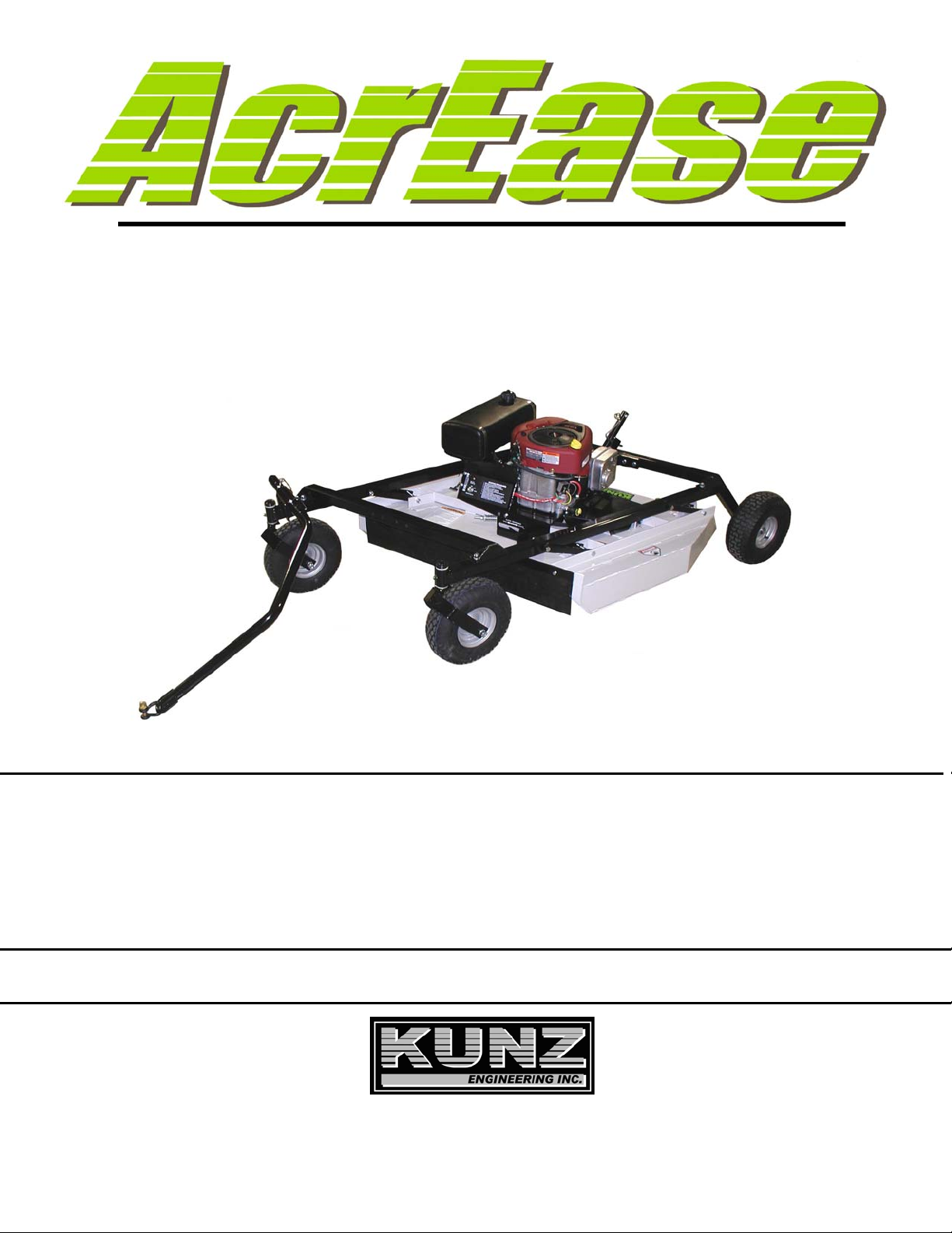
3. Install the two carrier arm assemblies in the pivot arms, which are located on the mower deck
assembly. Place the assembly so that the castered tires are on the front and the fixed tires are
on the back. See figure 2. Secure with 1/2" x 3-1/2" hex head bolts and lock nuts provided on
the pivot arms.
Note: Tighten 1/2” x 3-1/2” hex head bolts until just snug. This area needs to pivot when
adjusting the height. Under tightening can result in excessive wear and flexing. Over
tightening will make adjusting the cutting height very difficult.
Figure 2: Carrier Arm Installation
B. INSTALLATION OF CROSS BRACE TUBES AND HEIGHT ADJUST ASSY.
For this section, if your mower was purchased with an Electric Lift Kit (Part #003912), refer to
Section C of the Electric Lift Kit Owner’s Manual.
1. Remove the 1/2” x 3” hex head bolts, lock washers and nuts that are located on the top of
each carrier arm (four per carrier arm). The removed hardware will be used in step 2.
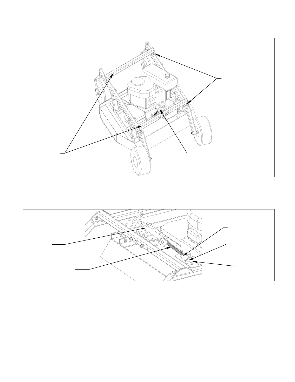
2. Install the cross brace tubes on the carrier arms with the 1/2” x 3” hex head bolts, lock washers
and nuts. Only hand tighten the hardware for this step. The support that has the height adjust
assy. fastened to it needs to be placed on the rear location. Orientate the support such that
the height adjust assy. hangs towards the engine. See figure 3.
3. Remove the 1/2” x 1” bolt and lock nut from the lower deck mount. Manually turn the screw
down towards the deck until the screw mounting flat hole lines up with the lower deck mount
hole. After achieving alignment, attach the screw mounting flat with the 1/2” x 1” hex head bolt
and secure the bolt with the provided lock nut. Do not over-tighten. This location must be able
to pivot. See figure 4.
Rear Tire Assy.
(Attach on outside for
both left and right sides)
Pivot Arm
Front (Rubber
Flap Side)
Carrier Arm
Assy.
1/2” x 3-1/2” Bolt

6
Figure 3: Cross Brace Tube Installation
Figure 4: Height Adjust Assy. Installation
4. Turn the crank on the height adjust assy. and raise the mower to its highest position. At this
time securely tighten the 1/2” x 3” hex head bolts, lock washers and nuts holding the cross
brace tubes in place. This step insures that proper alignment of the carrier arms has been
achieved.
Height Adjust Assy.
Cross Brace
Tube
1/2” x 3” Bolt
Screw Mounting
Flat
Height Adjust
Assy. 1/2” x 1” Bolt
Lower Deck
Mount
Screw

7
C. INSTALLATION OF TONGUE ASSEMBLY
1. The tongue can be installed either on the left or right carrier arm assembly depending on how
the tow-behind mower will be towed. See figure 5. Secure the hitch pivot on the chosen
carrier arm assembly with the 1/2” x 3-1/2” hex head bolt, lock washer, and nut provided.
2. Install the tongue into the hitch pivot and secure by placing the provided 5/16” wire lock pins on
each side of the hitch pivot.
Note: To help prevent any unwanted pin removal caused by oncoming debris install the 5/16”
wire lock pins with the wire lock section back from the direction of travel. See Figure 6.
Figure 5: Assembly of the Tongue and Hitch Pivot
Hitch Pivot – Attach to
Either Left or Right
Carrier Arm Assy.
Tongue
Carrier Arm
Assy.
Direct Behind PositionOffset Position

8
Figure 6: ATV Tongue Assembly
OPERATIONS AND ADJUSTMENTS
This safety alert symbol is used to indicate safety instructions. Follow
these instructions to avoid personal injury and/or property damage.
Read and follow all instructions in this manual and the attached engine
manual.
WARNING: Do not allow anyone to operate this equipment who has not fully read and
comprehended the safety manual and who has not been properly trained in the safe
operation of the equipment.
WARNING: Operator should be familiar with all functions of the unit.
A. TONGUE CONFIGURATIONS AND ADJUSTMENTS
WARNING: Shut off the engine and allow the mower blades to come to a complete stop
before adjusting the tongue.
The hitching system is designed so that the rough cut mower can be pulled directly behind a tow
vehicle or offset to the left or right. See Figure 7.
Note: When pulling the mower directly behind, the hitch pivot should be fastened on the right
carrier arm for maximum maneuverability. See Figure 5. When pulling the mower in
the offset position the hitch pivot can be fastened on either the right or left carrier arm.
See Figure 5.
Wire Lock Section of
Wire Lock Pin
(Placed Back From
Direction of Travel)
5/16” Wire
Lock Pins
Direction of Travel Screw Pin Shackle
Clevis
Tongue
Shift Tongue Left or Right
Between Holes

9
The tongue is equipped with a screw pin shackle clevis to provide movement in all directions on
rough uneven ground. To prevent loss of the screw pin due to vibration or debris, place the screw
pin through the tow vehicle hitch and clevis and turn the screw pin until snug.
The tongue is designed to adjust from left to right within the hitch pivot. This allows the mowers
position to be varied behind the tow vehicle. This is accomplished by pulling the 5/16” wire lock
pins out and choosing two other hole locations on the tongue. See Figure 6.
Figure 7: Rough Cut Tow Behind Towing Suggestions
B. ADJUSTING CUTTING HEIGHT
WARNING: Shut off the engine and allow the mower blades to come to a complete stop
before adjusting the cutting height.
Figure 8: Adjusting Rough Cut Mower Cutting Height
OffsetDirectly Behind
Measure This Distance
and Add 1-5/16” to get
Cutting Height
Cutting Height
1-5/16”
Smooth
Surface
Lower Edge of
Deck
Mower Blade
Adjustment Crank: Roughly 8
turns e
q
uals 1.0”

10
The cutting height can be adjusted in a range from 2.0" to 8.0". This is accomplished by turning
the height adjust crank located at the back of the mower. See Figure 8. Turn the crank clockwise
to raise the mower cutting height and counter-clockwise to lower the mower cutting height.
DANGER: Shut off tow vehicle engine and allow mower blades to stop completely before
attempting to measure the cutting height.
Adjust the mower as follows:
1. Pull the mower on to a smooth, level surface.
2. The desired cutting height can be determined by measuring the distance from the ground to
the outside lower edge of the mower deck and adding 1-5/16”. The mower blade cutting edge
is 1-5/16” above the outside lower edge of the mower deck.
Note: If the height adjust crank does not turn easily, the pivot bolts holding the carrier arm
assemblies and height adjust screw may be too tight. Loosen the pivot bolts slightly to
allow easier pivoting. Care should be taken not to loosen too much or excess wear and
flexing may occur. Greasing the threads on the height adjust screw may also allow
greater ease in adjustment.
Note: After setting the initial cutting height, quick field adjustments can be completed by
counting crank turns. Roughly 8 turns will equal 1” of vertical movement.
The adjustment crank may unturn due to vibration. This will allow the mower’s cutting height to
change. The crank can be secured by folding it down between the adjustment nut tube and the
height adjust support. See Figure 9.
Figure 9: Securing Crank While Not In Use
Adjustment Crank
Height Adjust Support
Adjustment Nut Tube

11
C. STARTING ENGINE
WARNING: Set parking brake on tow vehicle.
Attach mower tongue to tow vehicle.
WARNING: Do not start rough cut mower unless it is attached to the tow vehicle.
Turn on fuel shut off valve which is located on the underside of the gas tank.
Set the choke to the desired position.
Set the throttle at approximately half throttle.
Start engine and allow engine to warm up.
Set engine speed at about half throttle and slowly engage mower blades clutch handle. (The
clutch handle is located at the front of the mower under the engine.)
Note: Some belt squealing may occur on engagement. This is normal for a manual clutch
engagement design.
CAUTION: If the mower’s engine dies while in use, remove the rough cut mower from the
uncut area before attempting to engage the clutch. Inspect the blades for any obstructions
that may prevent blade engagement. Failure to follow these instructions may result in
premature belt failure or a fire.
Adjust engine speed to full throttle.
D. SHUTTING OFF ROUGH CUT MOWER
WARNING: Shift to neutral and set the parking brake before dismounting the tow vehicle.
Slow the engine speed down to an idle and slowly disengage the clutch handle.
Allow engine to cool down for a short time before moving the ignition switch to the off position.
Turn off fuel shut off valve which is located on the underside of the gas tank.
E. MOWER OPERATION
DANGER: Keep hands, feet, hair and clothing away from moving parts.
CAUTION: Clean or replace any safety signs that are not readable or damaged.

12
WARNING: Remove all objects from the work area that might be picked up and thrown by
the blades.
WARNING: Do not mow when children and others are around.
WARNING: Do not fill fuel tank while engine is running or hot.
WARNING: Keep all safety shields and deflectors in place during operation.
CAUTION: Remove grass build up from under safety shields before each use. Do not
remove safety shields while engine is running. Dry grass build up around belts and
sheaves can cause fires.
WARNING: Shut off engine before disconnecting the mower from the tow vehicle or
attempting to move the wing mower by hand.
WARNING: Never carry children or passengers.
WARNING: Do not allow children to operate this machine.
CAUTION: Slow down and watch the ends of the mower when making turns so objects
are not struck and/or run over.
WARNING: Look down, to the sides, and behind before and while backing to avoid
backing over something or someone. Care should also be taken while backing so that the
wing mower or mowers do not jackknife and damage hitches.
WARNING: Stop the mower blades on the mower if the tow vehicle becomes stuck or
stops going forward because of loss of traction. Shut off the engine on the mower before
attempting to push or pull the tow vehicle.
Listen to the rough cut mower engine while mowing. The engine should run free and not work too
hard. Working the engine too hard will cause overheating and premature failure.
CAUTION: If the mower’s engine dies while in use, remove the rough cut mower from the
uncut area before attempting to engage the clutch. Inspect the blades for any obstructions
that may prevent blade engagement. Failure to follow these instructions may result in
premature belt failure or a fire.
Do not allow material to build up on the air inlet to the engine cooling system. Special care should
be taken to make sure the engine is getting enough inlet air. Do not allow the engine cooling fins
under the shroud to be blocked. If air flow over the engine is restricted, the engine could
overheat.

13
F. DRIVE BELT REMOVAL AND TENSION – Refer to Figure 10
WARNING: Shut off engine and allow mower blades to stop turning before making any
adjustments or repairs.
Remove the safety shields.
Loosen the nuts on the spring-loaded idler; adjust bolt until the belt can be slipped off the idler and
drive sheaves.
Slip the belt down under the drive sheave and off the blade spindle sheaves.
Install the new belt and then adjust the tension as follows: See Figure 10. Take special care to
make sure that the belt is placed between the brake stud and the idler pulley.
Figure 10: Belt Pattern, Spring Adjustment, and Brake Adjustment
No Less Than 1/2” Clearance With
Clutch Engaged
0” With Clutch Disengaged
Brake Stud
Clutch Engaged
Spring Length 2-3/4”
to 3-1/4”
Clutch Disengaged
Spring Length 3-1/4”
to 4”
Clutch Arm
Engine
Fron
t
Clutch Engagement
Only Include
Spring in
Measurement

14
With the clutch engaged, adjust the nuts on the spring-loaded idler adjuster bolt until the length of
the spring is approximately 2-3/4”. This is the initial belt break in spring length. When the belt is
broken in after several hours of mowing, the running spring length should be between 2-3/4” and
3-1/4”. For maximum belt life, periodic checks every 3-4 hours should be done to make sure the
spring length has not exceeded the recommended running length.
Note: Failure to periodically adjust the belt tension will result in severe belt wear and
premature belt failure.
This model comes with a belt brake, which is a safety feature that stops the blades from turning
after the clutch is disengaged. The only time the brake should be in contact with the belt is when
the clutch is disengaged.
CAUTION: The brake stud may need to be adjusted if there is significant belt wear or if a
different size belt is used. If the brake stud is not adjusted correctly, the blades will still
spin even though the clutch may be in the disengaged position. Always shut mower
engine off before servicing.
Under normal operating conditions and when using the Kunz Engineering belt (Part # 238007) the
brake stud should require very little adjustment. Periodic brake stud inspections should be
performed every 10 hours. In more severe cutting conditions, more frequent inspections may be
necessary. There are two parts to inspecting the brake stud. Those two inspections are the
disengaged spring length and brake stud clearance.
Note: It is quicker to perform the disengaged spring length and brake stud clearance
inspections if done simultaneously.
Disengaged Spring Length:
This inspection must be performed to make sure that there is proper braking force to prevent the
blades from spinning when the clutch is in the disengaged position. With the clutch in the
disengaged position measure the spring length. The spring must be between 3-1/4” and 4” to
provide the appropriate braking force. If the spring length is over 4” it will be necessary to adjust
the brake stud closer to the belt. If the spring length is less than 3-1/4” it will be necessary to
adjust the brake stud further away from the belt. To make brake stud adjustments loosen the bolt
on the top of the brake stud and slide the brake stud in the slot. When the proper disengaged
spring length is achieved, tighten the bolt on the top of the brake stud. For this procedure do not
adjust the spring length. The spring length should only be changed when adjusting the belt
tension.
Brake Stud Clearance:
This inspection is necessary to prevent over-braking. To inspect the brake stud clearence it is
easiest to remove the left belt sheild and observe from the left side. With the clutch engaged,
check to make sure that there is at least 1/2” of clearance between the brake stud and the belt. If
the clearance is less than 1/2” then it will be necessary to adjust the brake stud away from the
belt. Keep in mind that the disengaged spring length must stay between 3-1/4” and 4”.

15
Note: If the brake stud is adjusted to the end of the slot and the brake stud clearance is under
1/2” then it is time to replace the belt.
CAUTION: If brake stud is not set in correct position, under-braking or over-braking may
occur. If over-braking occurs, premature belt failure or a possible fire could occur due to
excessive friction and overheating.
G. MOWER BLADE REMOVAL, BALANCING & INSTALLATION
CAUTION: Sharp blades can cause bodily injury if not handled properly.
When removing the blade, it is recommended that a block of wood be placed between the blade
and the underside of the mower deck. This will allow the removal of the blade without the need to
hold the blade by hand.
CAUTION: Always balance the mower blades each time they are sharpened.
Out of balance mower blades cause excessive vibrations which lead to premature bearing
failures, bolts coming loose, and overall deterioration of the mower.
CAUTION: Always properly tighten the blade bolts to the specified torque. Failure to do so
can lead to unwanted loosening of the blade and damage to the blade holding saddle.
The Models MR44B and MR44V use the Kunz Engineering Part # (202141) blade bolt. This
particular hex head bolt is a 3/4” – 16NF x 1-1/4” long, grade 5 and its proper torque is 300 ft-lbs.
To ease in the blade installation process, use the same block of wood and method used during
the removal of the blades.
H. LUBRICATION
There are three lubrication points on the rough cut mower -- one spring-loaded idler pivot and
two caster wheel pivots. Lubricate at approximately 10 hr. intervals or more often as required in
dusty conditions.
I. STORAGE
Turn off fuel shut off valve which is located on the underside of the gas tank. If the mower is
stored outside, the engine should be covered to prevent water from getting inside the engine
during heavy rainstorms. See the Engine Manual for additional information.

16
J. EPA EVAPORATIVE COMPONENTS
This mower has been designed and built to meet all current EPA regulations. Any modification to
the fuel tank, fuel lines, vapor hose, fuel cap, roll-over / fuel vapor valve, carbon canister
(California Only) and hose clamps are prohibited. Replacement evaporative components should
be purchased from Kunz Engineering. Any questions about EPA regulations or evaporative
components can be directed to Kunz Engineering Inc. at 815-539-6954.

17
ACREASE ROUGH CUT MOWER SPECIFICATIONS
Model Model
MR44B MR44V
ENGINE:
Engine Make Briggs & Stratton Briggs & Stratton Commercial
Engine Model Intek Professional Vanguard
Cylinders 12
Cycles 44
Crankshaft Vertical Vertical
Engine HP 19 18
Bore 3.12" 2.84"
Stroke 3.06" 2.76"
Displacement 33.0 cu. In. 34.78 cu. In.
Oil Capacity 1.5 U.S. qt 1.5 U.S. qt
Crankshaft Dia. 1.0" 1.0"
Key Slot 1/4" 1/4"
Crankshaft Length 3.15" 3.15"
Threaded Hole in End of Crankshaft 7/16-20 7/16-20
Engine Mounting Bolts 5/16-18x1.50 Through Bolt 5/16-18x1.50 Through Bolt
Starter Electric Electric
Choke Manual Manual
MOWER:
Fuel Tank 3 Gal. 3 Gal.
Effective Cutting Width 44" 44"
Deck Construction 8 ga. Welded steel 8 ga. Welded steel
Cutting Height 2" to 8" 2" to 8"
Height Adjustment Single Crank Single Crank
Rear Wheels (Fixed) (4 ply Turf Pnuematic) Two 15/600 x 6 Two 15/600 x 6
Front Wheels (Caster) (4 ply Turf Pnuematic) Two 5.30/4.50 x 6 Two 5.30/4.50 x 6
Blade Dia. 2-23" 2-23"
Engine Speed, Blades Running 3500 RPM 3500 RPM
CLUTCH TYPE
Engagement Speed Manual Manual
DIMENSIONS
Length 95.5" 95.5"
Width 46.5" 46.5"
Height 29" 29"
Weight 520 lbs. 530 lbs.
HITCH
Hitch Type ATV Tongue ATV Tongue
TOUCH-UP PAINT COLOR Pewter Gray, Krylon #1606 Pewter Gray, Krylon #1606

18
ACREASE ROUGH CUT MOWER PARTS LIST
Item Part # Description Qua nti ty
1 202141 Blade Bolt, .75"-16UNF x 1.25" 2
2 214021 Cup Washer 6
3 216002 W ire Lo ck Pin, . 31" x 2 .50" 2
4 216009 Screw Pin Shackle Clevis 1
5 222005 W orm Drive Hose Clamp (7-7 /8" to 9 -1/8" Cl amping Dia.) 2
6 222012 Single Split Collar (1" I.D. x 1/2: Thick) 2
7 225005 Compression Spring, 4-1/2"L x 1-3/32" O.D. x .125" Wire dia. 1
8 226003 Offset W heel Assy. (15/ 600 x 6, 4 Ply Turf) 2
8 226008 Offset Wheel Assy. (15/600 x 6, Urethane Foam-Flatproof) Optional
9 226004 Centered Wheel Assy. (5.30/4.50 x 6, 4 Ply Stud) 2
9 226009 Centered Wheel Assy. (5.30/4.50 x 6, Urethane Foam-Flatproof) Optional
10 238007 "V" Belt, .62" x 77" O.C. (B74K) 1
11 241001 Flat Idler, 4" O.D. x 3/8" Hole 1
12 241010 "V" Sheave, 5" Dia. 1" Bore 1
13 243007 Precision Sealed Wheel Bearings (1-3/8" O. D. x 5/8" I. D.) 8
14 243010 Plastic Bearing (1-3/8" O.D. x 1.00" I.D., Flange, Nylon) 4
15 258023 Spindle Assy. 2
900075 Spindle Shaft (1)
900160 Housing Assy. (With Two Bearings) (1)
243006 Bearing (6206 w/ Trash Guard Seals) (2)
600271 Bearing Spacer (3.33" Long) (1)
241011 Sheave, (5.56" Dia. , B-Section) (1)
16 259008 Offset Mower Blade, 2-1/2" Wide, 23" Long, 3/4" Hole 2
17 260004 Roll-Over / Fuel Vapor Valve (Includes Gromet) 1
18 264000 Solenoid 1
19 264010 Ignition Switch 1
20 264003 Hour/Tack Meter Optional
21 269000 Choke Control, 20" (MR44B) 1
21 269010 Choke Control, 27" (MR44V) 1
22 269001 Throttle Cont rol, 15" (MR44B) 1
22 269009 Throttle Cont rol, 27" (MR44V) 1
23 275001 Control Panel Decal, Starting Instructions 1
23 275002 W arni ng Decal Ge neral 1
23 275003 Danger Decal, Cut Finger 2
23 275007 W arning Decal, Belt Sheild 2
23 275011 Clutch Engagement Decal 1
23 275019 Name Decal,Kunz 1
23 275021 Name Decal, AcrEase 1
23 275024 Name Decal, 44" Rough Cut 1
24 277002 Rubber Gromet 6
25 277011 Handle Grip 1
26 277035 Gas Cap - Audible Click/Tethered, Non-Venting 1
27 277036 Carbon Canister - 300cc (California Only) 1
28 277040 Fuel Tank, 3 Gal., 3-Layer EPA Certified 1
29 600071 Spacer, 1.38" O.D. x 1.33" Wall x 2.19" Long 1
30 600136 Brake Stud 1
31 600146 Crank Arm 2

19
Item Part # Description Quant ity
32 600185 Top Lon g Support 1
33 600186 Top Shor t Support 1
34 600252 Flap Retainer Strip 1
35 600253 Safety Belting 1
36 600254 Battery Box Spacer 2
37 600264 Belt Sheild, Left 1
38 600265 Belt Sheild, Right 1
39 600268 Height Adjust Support 1
40 600291 Canister Support (California Only) 1
41 600292 Clutch Arm 1
42 900023 Control Panel 1
43 900049 Battery Box Assy. 1
44 900058 Hitch Pivot 1
45 900061 Pivot Arm 4
46 900079 Tank Support 1
47 900082 Tongue 1
48 900148 Caster Fork 1
49 900150 Engine Support Bracket 1
50 900154 Upper Actuator Mou nt 2
51 900155 Carrier Arm 2
52 900156 Mower Deck 1
53 900157 Height Adjust Nut 1
54 900158 Screw Adjuster 1
55 900180 Idler Arm Assy. 1
243005 Bronze Bearing, 1/2"I.D. x 3/4" O.D. x 3/4" Long 2
This manual suits for next models
1
Table of contents
Other Kunz Lawn Mower manuals

Kunz
Kunz AcrEase MR55B User manual

Kunz
Kunz AcrEase MR44B Datasheet

Kunz
Kunz AcrEase C60BE User manual

Kunz
Kunz AcrEase MR44BE Datasheet

Kunz
Kunz AcrEase MR44B User manual

Kunz
Kunz AcrEase MR55K Datasheet

Kunz
Kunz AcrEase MR55KEI Datasheet

Kunz
Kunz AcrEase MR55B User manual

Kunz
Kunz AcrEase Pro60K-25HP User manual

Kunz
Kunz AcrEase MR55KE User manual
Popular Lawn Mower manuals by other brands

Bushranger
Bushranger 53TBU65 Assembly and owner's manual

Billy Goat
Billy Goat FM3301 Operator owner's manual

Yazoo
Yazoo YHRLD21 Illustrated parts list

Swisher
Swisher POL 10550 owner's manual

Snapper
Snapper P216012 Safety instructions & operator's manual

Hyundai power products
Hyundai power products HYM40Li420P instruction manual