Kunz AcrEase MR55BE Datasheet

1
12/20
57” ROUGH CUT
WITH ELECTRIC CLUTCH BLADE ENGAGEMENT
OWNER’S MANUAL
With Assembly Instructions
For Models: MR55BE & MR55KE-25HP
KUNZ ENGINEERING, INC. / MENDOTA, IL 61342 / PH (815) 539-6954

2

1
TABLE OF CONTENTS
SAFETY INTRODUCTION……………………………………………………………………………… 2
Safety Alert Symbol …………………………………………………………………………………… 2
Safety Information ………………………………………………………………………………………3
Safety Signs and Locations ……………………………………………………………………………4
ASSEMBLY INSTRUCTIONS ………………………………………………………………………......5
Items Included …………………………………………………………………………………………..5
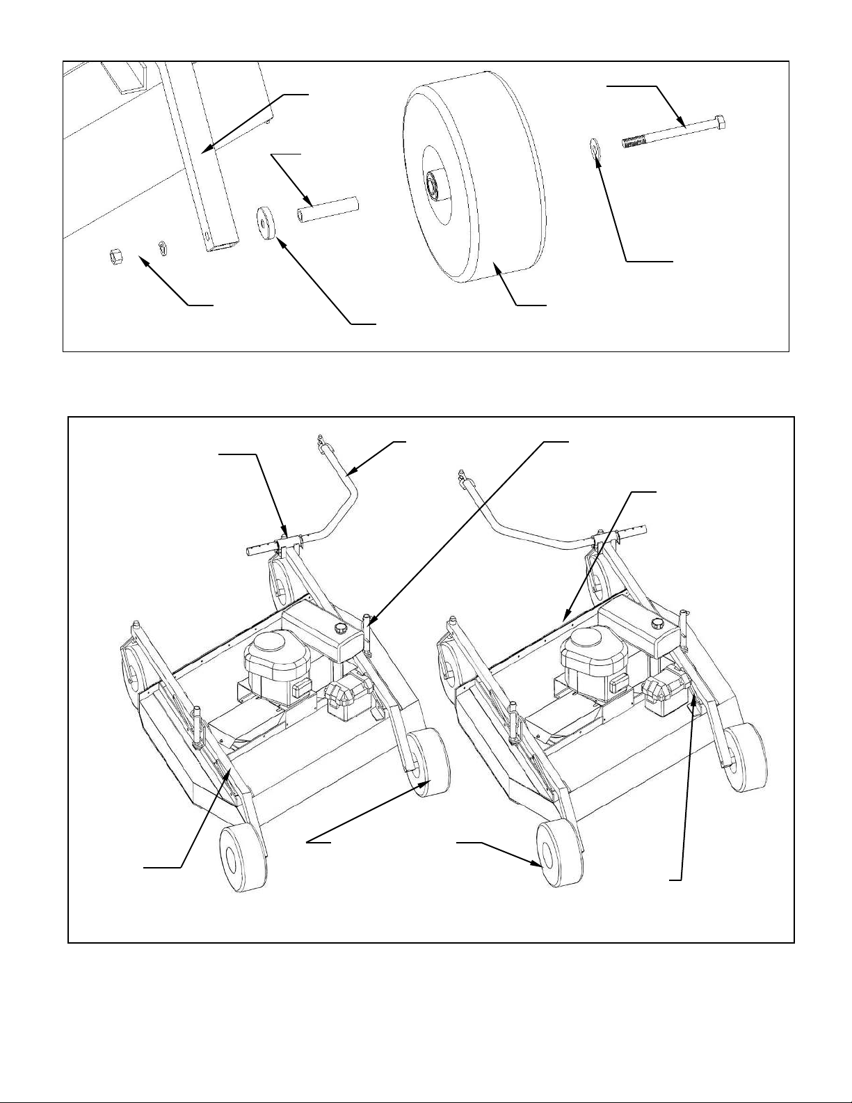
Assembly of Mower Wheels ………………………………………………………………………….. 5
Installation of Tongue Assembly ……………………………………………………………………...5
OPERATION AND ADJUSTMENTS ………………………………………………………………….. 7
Intended Use …………………………………………………………………………………………… 7
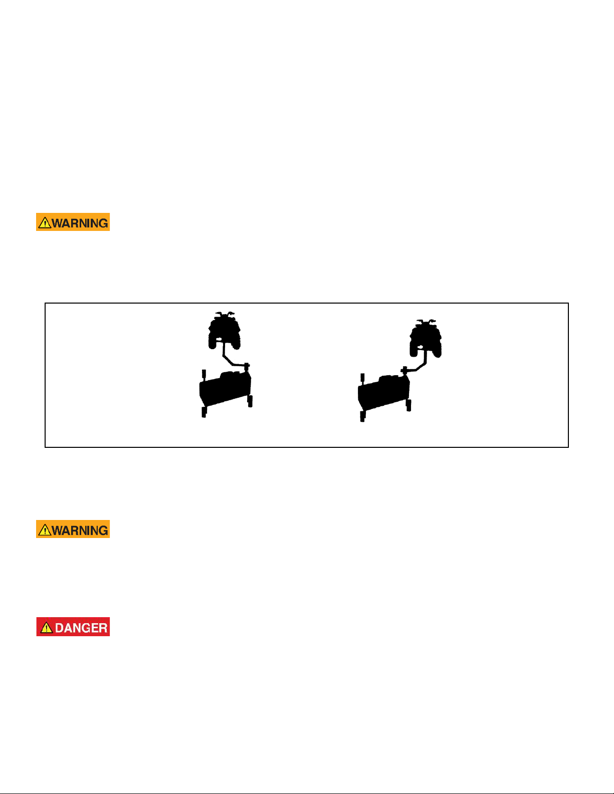
Tongue Configurations and Adjustments …………………………………………………………… 7
Adjusting Cutting Height ………………………………………………………………………........... 8
Starting Engine …………………………………………………………………………………........... 10
Shutting Off Mower ……………………………………………………………………………............ 11
Mower Operation ………………………………………………………………………………............ 11
MAINTENANCE …………………………………………………………………………………………..12
Drive Belt Removal and Tension …………………………………………………………………….. 12
Mower Blade Removal, Balancing & Installation …………………………………………………… 13
Lubrication ……………………………………………………………………………………………… 14
Engine Maintenance …………………………………………………………………………….…….. 14
Fuse Location ………………………………………………………………………………………….. 14
Storage …………………………………………………………………………………………………. 14
EPA Evaporative Components ………………………………………………………………………. 14
SPECIFICATIONS ………………………………………………………………………………………..15
Engine ……………………………………………………………………………………………………15
Mower …………………………………………………………………………………………………… 15
Weight & Dimensions …………………………………………………………………………............ 15
SERVICE PARTS …………………………………………………………………………………………16
Parts List …………………………………………………………………………………………………16
Parts Drawing ………………………………………………………………………………………….. 18
OPTIONAL EQUIPMENT ………………………………………………………………………………..19
Wetlands Kit ……………………………………………………………………………………………. 19
Electric Lift Kit ………………………………………………………………………………………….. 20
Floatation Kit …………………………………………………………………………………………… 21
WARRANTY STATEMENT …………………………………………………………………………….. 22

2
SAFETY INTRODUCTION
READ AND UNDERSTAND OWNER’S MANUAL BEFORE USING THIS MACHINE.
All operators of this equipment must read and completely understand all safety information,
operating instructions and maintenance. Failure to properly operate and maintain this
mower could result in serious injury or death to the operator or bystanders.
Your safety, and the safety of others, is very important. To help you make informed
decisions about safety, we have provided operating procedures and other information on
labels and in this manual. This information alerts you to potential hazards that could hurt
you or others.
This safety alert symbol is used to indicate safety instructions. Follow these
instructions to avoid personal injury and/or property damage. Read and follow all
instructions in this manual and the included engine manual.
You will find important safety information in a variety of forms, including:
Safety Labels –on the mower.
Safety Messages –preceded by a safety alert symbol and one of three signal
words: DANGER, WARNING, or CAUTION.
These signal words mean:
Indicates an imminently hazardous situation that, if not avoided, will result in death or
serious injury. This signal word is to be limited to the most extreme situations
typically for machine components which, for functional purposes, cannot be guarded.
Indicates a potentially hazardous situation that, if not avoided, could result in death or
serious injury, and includes hazards that are exposed when guards are removed. It
may also be used to alert against unsafe practices.
Indicates a potentially hazardous situation that, if not avoided, may result in minor or
moderate injury. It may also be used to alert against unsafe practices.
This entire manual is filled with important safety information. Please read it
carefully.
If you have any questions or concerns regarding the information in this owner’s
manual please contact Kunz Engineering at 815-539-6954.

3
IMPORTANT SAFETY INFORMATION
Do not allow anyone to operate this equipment who has not fully read and
comprehended the safety manual and who has not been properly trained in the safe
operation of the equipment.
Operator should be familiar with all functions of the unit.
Keep hands, feet, hair and clothing away from moving parts.
Remove all objects from the work area that might be picked up and thrown by the
blades.
Do not mow when children and others are around.
Keep all safety shields and deflectors in place during operation.
Shut off the engine and allow the mower blades to come to a complete stop before
making any adjustments to the mower.
Shut off engine before disconnecting the wing mower from the tow vehicle or
attempting to move the wing mower by hand.
Never carry children or passengers.
Do not allow children to operate this machine.
Follow all safety precautions outlined by the manufacturer of the tow vehicle being
used to pull this product.
This entire manual is filled with important safety information. Please read it
carefully.

4
SAFETY SIGNS AND LOCATIONS
Clean or Replace Any Safety Signs That Are not Readable or Damaged
Replacement decals can be purchased from your local dealer or
Kunz Engineering Inc.
Mendota, IL 61342
(815) 539-6954
275003 –Danger
Decal, Cut Hand & Foot
275007 –Warning
Decal, Belt Sheild
275002 –Warning
Decal, General
Serial # and Model #
Decal

5
ASSEMBLY INSTRUCTIONS
Read the complete assembly instructions before starting the assembly.
You should have:
- one mower deck assembly
- two carrier arm assemblies
- two rear tire assemblies
- one ATV tongue assembly
A. ASSEMBLY OF MOWER WHEELS
1. Set the mower deck assembly on wood blocks so that it is suspended off the ground.
Note: The operator controls are on the front of the deck. (Left and right are determined by
looking in the direction of travel or by standing at the rear of the deck assembly looking
forward.)
2. Install the rear tire assemblies on the carrier arm assemblies. Remove the hex nut and lock
washer from the rear tire assembly and install the 5/8”x7-1/2” tire axle bolt through the hole in
the carrier arm assembly. See figure 1. Secure assembly with the lock washer and hex nut
provided on the rear tire assembly. The rear tires should be offset to the outside of the deck
assembly on both sides. See figure 2.
3. Install the two carrier arm assemblies in the pivot arms, which are located on the mower deck
assembly. Place the assembly so that the castered tires are on the front and the fixed tires are
on the back. See figure 2. Secure with 1/2" x 3-1/2" hex head bolts and lock nuts provided on
the pivot arms. Mount the height adjust screw on the deck assembly in the hole provided.
Secure with the 1/2”x1” hex head bolt and lock nut provided on the height adjust screw.
Note: Tighten 1/2” x 3-1/2” and 1/2” x 1” hex head bolts until just snug. This area needs to
pivot when adjusting the height. Under tightening can result in excessive wear and
flexing. Over tightening will make adjusting the cutting height very difficult.
B. INSTALLATION OF TONGUE ASSEMBLY
1. The tongue can be installed either on the left or right caster assembly depending on how the
tow-behind mower will be towed. See figure 2. Secure the hitch pivot on the chosen caster
assembly with the 1/2” x 3-1/2” hex head bolt, lock washer, and nut provided.
2. Install the tongue into the hitch pivot and secure by placing the provided 5/16” wire lock pins on
each side of the hitch pivot.
Note: To help prevent any unwanted pin removal caused by oncoming debris install the 5/16”
wire lock pins with the wire lock section back from the direction of travel. See Figure 3.

6
Figure 1: Rear Tire Assembly Installation
Figure 2: Assembly of Carrier Arm Assy., Hitch Pivot, and Tongue
Rear Tire Assy.
(Attach on outside for
both left and right sides)
Pivot Arm
Height Adjust
Screw
Hitch Pivot –Attach to
Either Left or Right
Carrier Arm Assy.
Tongue
Front (Rubber
Flap Side)
Carrier Arm
Assy.
Direct Behind Position
Offset Position
Flat Washer
Rear Tire
Carrier Arm
Assembly
Hex Nut and
Lock Washer
Cup Washer
Bolt
Spanner
Tube

7
Figure 3: ATV Tongue Assembly
OPERATIONS AND ADJUSTMENTS
This safety alert symbol is used to indicate safety instructions. Follow
these instructions to avoid personal injury and/or property damage.
Read and follow all instructions in this manual and the attached engine
manual.
Do not allow anyone to operate this equipment who has not fully read and
comprehended the safety manual and who has not been properly trained in the safe
operation of the equipment.
Operator should be familiar with all functions of the unit.
A. INTENDED USE
This mower is intended for use behind an ATV, UTV (utility vehicle / side-by-side) or small tractor
to cut grass, weeds, brush and saplings up to 2”in diameter.
B. TONGUE CONFIGURATIONS AND ADJUSTMENTS
Shut off the engine and allow the mower blades to come to a complete stop before
adjusting the tongue.
The hitching system is designed so that the rough cut mower can be pulled directly behind a tow
vehicle or offset to the left or right. See Figure 4.
Wire Lock Section of
Wire Lock Pin
(Placed Back From
Direction of Travel)
5/16” Wire
Lock Pins
Direction of Travel
Screw Pin Shackle
Clevis
Tongue
Shift Tongue Left or Right
Between Holes

8
Note: When pulling the mower directly behind, the hitch pivot should be fastened on the right
carrier arm for maximum maneuverability. See Figure 2. When pulling the mower in
the offset position the hitch pivot can be fastened on either the right or left carrier arm.
See Figure 2.
The tongue is equipped with a screw pin shackle clevis to provide movement in all directions on
rough, uneven ground. To prevent loss of the screw pin due to vibration or debris, place the
screw pin through the tow vehicle hitch and clevis and turn the screw pin until tight. Use of pliers
or a similar type of tool will be necessary to fully tighten the shackle pin.
Failure to properly tighten the shackle pin could result in the mower separating from
the tow vehicle.
The tongue is designed to adjust from left to right within the hitch pivot. This allows the mowers
position to be varied behind the tow vehicle. This is accomplished by pulling the 5/16” wire lock
pins out and choosing two other hole locations on the tongue. See Figure 3.
Figure 4: Rough Cut Tow Behind Towing Suggestions
B. ADJUSTING CUTTING HEIGHT
Shut off all engines and allow the mower blades to come to a complete stop before
adjusting the cutting height.
The cutting height can be adjusted in a range from 2.0" to 8.0". This is accomplished by turning
the height adjust cranks on both sides of the mower. See Figure 5. Turn the cranks clockwise to
raise the mower cutting height and counter-clockwise to lower the mower cutting height.
Shut off tow vehicle engine and allow mower blades to stop completely before
attempting to measure the cutting height.
Offset
Directly Behind

9
Adjust the mower as follows:
1. Pull the mower on to a smooth, level surface.
2. Adjust the mower evenly from side to side by measuring to the ground from the lower edge of
the mower deck. The desired height will be the distance from the ground to the outside lower
edge of the mower deck plus 1-5/16”. The mower blade cutting edge is 1-5/16” above the
outside lower edge of the mower deck.
Note: If the height adjust cranks do not turn easily, the pivot bolts holding the carrier arm
assemblies and height adjust screw may be too tight. Loosen the pivot bolts slightly to
allow easier pivoting. Care should be taken not to loosen too much or excess wear and
flexing may occur. Greasing the threads may also allow greater ease in adjustment.
Note: After leveling mower deck, quick field adjustment can be completed by counting crank
turns. Roughly 6 turns will equal 1” of vertical movement.
Figure 5: Adjusting Rough Cut Mower Cutting Height
The adjustment crank may unturn due to vibration. This will allow the mower’s cutting height to
change. The crank can be secured by folding it down between the adjustment nut tube and the
upper pivot support. See Figure 6.
Measure This Distance
and Add 1-5/16” to get
Cutting Height
Cutting Height
1-5/16”
Smooth Surface
Lower Edge of
Deck
Mower Blade
Adjustment Crank: Roughly 6
turns equals 1.0”

10
Figure 6: Securing Crank While Not In Use
C. STARTING ENGINE
Set parking brake on tow vehicle.
Attach mower tongue to tow vehicle.
Do not start rough cut mower unless it is attached to the tow vehicle.
Turn on the fuel shut off valve (red colored rotating knob) located inline on the fuel hose. The off
position on the valve is when the red handle lines up with the “O” symbol.
Set the choke to the desired position.
Set the throttle at approximately half throttle.
Start engine and allow engine to warm up.
Set the engine speed at about half throttle and engage the mower blades clutch by pulling
outward on the PTO switch. (The PTO switch is located at the front of the mower deck on the
control panel.)
Note: To help extend the life of the clutch the engine rpm should be placed as low as possible
before clutch engagement. If the engine should stall during clutch engagement raise
the engine rpm until clutch engagement is possible.
If the mower’s engine dies while in use, remove the rough cut mower from the uncut
area before attempting to engage the clutch. Inspect the blades for any obstructions
that may prevent blade engagement. Failure to follow these instructions may result
in premature clutch and belt failure or a fire.
Adjust engine speed to full throttle.
Adjustment Crank
Carrier Arm
Adjustment Nut Tube
Upper Pivot Support

11
D. SHUTTING OFF ROUGH CUT MOWER
Shift to neutral and set the parking brake before dismounting the tow vehicle.
Slow the engine speed down and disengage the clutch by pushing inward on the PTO switch.
Allow engine to cool down for a short time before moving the ignition switch to the off position.
Turn off the fuel shut off valve (red colored rotating knob) located inline on the fuel hose. The off
position on the valve is when the red handle lines up with the “O” symbol.
E. MOWER OPERATION
Keep hands, feet, hair and clothing away from moving parts.
Clean or replace any safety signs that are not readable or damaged.
Remove all objects from the work area that might be picked up and thrown by the
blades.
Do not mow when children and others are around.
Do not fill fuel tank while engine is running or hot.
Keep all safety shields and deflectors in place during operation.
Remove grass build up from under safety shields before each use. Do not remove
safety shields while engine is running. Dry grass build up around belts and sheaves
can cause fires.
Shut off engine before disconnecting the mower from the tow vehicle or attempting to
move the wing mower by hand.
Never carry children or passengers.
Do not allow children to operate this machine.
Slow down and watch the ends of the mower when making turns so objects are not
struck and/or run over.
Look down, to the sides, and behind before and while backing to avoid backing over
something or someone. Care should also be taken while backing so that the wing
mower or mowers do not jackknife and damage hitches.

12
Stop the mower blades on the mower if the tow vehicle becomes stuck or stops going
forward because of loss of traction. Shut off the engine on the mower before
attempting to push or pull the tow vehicle.
Inspect the ATV Tongue Assembly and tow vehicle hitch before each use. If any
parts of the tongue or hitch look damaged or severely worn, discontinue use of the
mower until the damaged or worn parts are replaced.
Engine exhaust contains carbon monoxide. Do not run engine indoors or in a small
confined area where dangerous carbon monoxide fumes can collect.
Wear hearing protection when operating this mower.
Engine components and exhaust can develop excessive heat. Keep the mower
clean of debris and other flammable material to avoid fires.
Follow all safety precautions outlined by the manufacturer of the tow vehicle being
used to pull this product.
Listen to the rough cut mower engine while mowing. The engine should run free and not work too
hard. Working the engine too hard will cause overheating and premature failure.
If the mower’s engine dies while in use, remove the rough cut mower from the uncut
area before attempting to engage the clutch. Inspect the blades for any obstructions
that may prevent blade engagement. Failure to follow these instructions may result
in premature belt failure or a fire.
Do not allow material to build up on the air inlet to the engine cooling system. Special care should
be taken to make sure the engine is getting enough inlet air. Do not allow the engine cooling fins
under the shroud to be blocked. If air flow over the engine is restricted, the engine could
overheat.
MAINTENANCE
A. DRIVE BELT REMOVAL AND TENSION –Refer to Figure 7
Shut off engine and allow mower blades to stop turning before making any
adjustments or repairs.
Remove the safety shields.
Loosen the nuts on the spring-loaded idler; adjust bolt until the belt can be slipped off the idler and
drive sheaves.
Slip the belt down under the drive sheave and off the blade spindle sheaves.

13
Install the new belt and then adjust the tension as follows: See Figure 7.
Figure 7: Belt Pattern and Spring Adjustment
Adjust the nuts on the spring-loaded idler adjuster bolt until the length of the spring is between 2-
1/2” and 2-9/16”. This is the initial belt break in spring length. When the belt is broken in after
several hours of mowing, the running spring length should be between 2-3/4” and 3-1/4”. For
maximum belt life, periodic checks every 3-4 hours should be done to make sure the spring length
has not exceeded the recommended running length.
Note: Failure to periodically adjust the belt tension will result in severe belt wear and
premature belt failure.
B. MOWER BLADE REMOVAL, BALANCING & INSTALLATION
Sharp blades can cause bodily injury if not handled properly.
When removing the blade, it is recommended that a block of wood be placed between the blade
and the underside of the mower deck. This will allow the removal of the blade without the need to
hold the blade by hand.
Engine/Clutch
Front
Initial Spring Length (New Belt):
2-1/2” to 2-9/16”
Running Spring Length:
2-3/4” to 3-1/4”
Only Include
Spring in
Measurement

14
Always balance the mower blades each time they are sharpened.
Out of balance mower blades cause excess vibrations which lead to premature bearing failures,
bolts coming loose, and overall deterioration of the mower.
Always properly tighten the blade bolts to the specified torque. Failure to do so can
lead to unwanted loosening of the blade and damage to the blade holding saddle.
The Models MR55BE and MR55KE use the Kunz Engineering Part # (202141) blade bolt. This
particular hex head bolt is a 3/4” – 16NF x 1-1/4” long, grade 5 and it’s proper torque is 300 ft-lbs.
To ease in the blade installation process, use the same block of wood and method used during
the removal of the blades.
C. LUBRICATION
There are three lubrication points on the rough cut mower -- one spring-loaded idler pivot and
two caster wheel pivots. Lubricate at approximately 10 hr. intervals or more often as required in
dusty conditions.
D. ENGINE MAINTENANCE
Refer to the engine manual provided in the owner’s manual packet.
E. FUSE LOCATION
These particular mowers come equipped with a 10 AMP mini blade type fuse. The fuse is located
behind the ignition switch/control panel in a black rubber inline fuse holder.
F. STORAGE
Turn off the fuel shut off valve (red colored rotating knob) located inline on the fuel hose. The off
position on the valve is when the red handle lines up with the “O” symbol. If the mower is stored
outside, the engine should be covered to prevent water from getting inside the engine during
heavy rainstorms. See the Engine Manual for additional information.
G. EPA EVAPORATIVE COMPONENTS
This mower has been designed and built to meet all current EPA regulations. Any modification to
the fuel tank, fuel lines, vapor hose, fuel cap, roll-over / fuel vapor valve, carbon canister
(California Only) and hose clamps are prohibited. Replacement evaporative components should
be purchased from Kunz Engineering. Any questions about EPA regulations or evaporative
components can be directed to Kunz Engineering Inc. at 815-539-6954.

15
ACREASE ROUGH CUT MOWER SPECIFICATIONS
Model Model
MR55BE MR55KE
ENGINE:
Engine Make Briggs & Stratton Kohler
Engine Model Commercial Turf Confidant
Cylinders 2 2
Cycles 4 4
Crankshaft Vertical Vertical
Engine HP 27 25
Bore 3.30" 3.30"
Stroke 2.89" 2.70"
Displacement 49.43 cubic inches 45.60 cubic inches
Oil Capacity 2.1 U.S. qts. 2 U.S. qts.
Crankshaft Dia. 1" 1"
Key Slot 1/4" 1/4"
Crankshaft Length 3.15" 3.15"
Threaded Hole in Crankshaft End 7/16-20 7/16-20
Engine Mounting Bolts 5/16-18 x 1.50" Through Bolt 3/8-16 x 1" Thread Rolling
Starter Electric Electric
Choke Manual Manual
Fuse 10 AMP 10 AMP
MOWER:
Fuel Tank 3 Gal. 3 Gal.
Effective Cutting Width 57" 57"
Deck Construction 10 ga. Welded steel 10 ga. Welded steel
Cutting Height 2" to 8" 2" to 8"
Height Adjustment 2 Cranks 2 Cranks
Rear Wheels (Fixed) Two 15/600 x 6 Two 15/600 x 6
(4 ply Turf Pnuematic)
Front Wheels (Caster) Two 5.30/4.50 x 6 Two 5.30/4.50 x 6
(4 ply Turf Pnuematic)
Blade Dia. 2-30" 2-30"
Engine Speed, Blades Running 3600 RPM 3600 RPM
CLUTCH TYPE Electric Electric
DIMENSIONS
Length 108" 108"
Width 60" 60"
Height 29" 29"
Weight 580 lbs 580 lbs
HITCH
Hitch Type ATV Tongue ATV Tongue
TOUCH-UP PAINT COLOR
Pewter Gray, Krylon #1606 Pewter Gray, Krylon #1606

16
ACREASE ROUGH CUT MOWER PARTS LIST
Item Part # Description Quantity
1202141 Blade Bolt, .75"-16UNF x 1.25" 2
2214030 Cup Washer 6
3216002 Wire Lock Pin, .31" x 2.50" 2
4216009 Screw Pin Shackle Clevis 1
5222005 Worm Drive Hose Clamp (7-7/8" to 9-1/8" Clamping Dia.) 2
6222012 Single Split Collar (1" I.D. x .1/2" Thick) 2
7225005
Compression Spring, 4.50"L x 1-3/32" O.D. x .125" Wire dia. 1
8226012 Offset Wheel Assy. (15/600 x 6, 2 Ply Turf) 2
8226014 Offset Wheel Assy. (15/600 x 6, Urethane Foam-Flatproof) Optional
9226013 Centered Wheel Assy. (5.30/4.50 x 6, 2 Ply Stud) 2
9226015 Centered Wheel Assy. (5.30/4.50 x 6, Urethane Foam-Flatproof) Optional
10 238004 "V" Belt, .62" x 95.9" O.C. 1
11 241001 Flat Idler, 4" O.D. x 3/8" Hole 1
12 241009 Flat Idler (Steel), 4" O.D. x 1/2" Hole 1
13 243010 Plastic Bearing, 1-3/8" O.D. x 1.00" I.D. 4
14 243015 Precision Sealed Wheel Bearings (2" O.D. x 1" I.D.) 8
15 258022 Spindle Assy. 2
900075 Spindle Shaft (1)
900160 Housing Assy. (With Two Bearings) (1)
243006 Bearing (6206 w/ Trash Guard Seals) (2)
600271 Bearing Spacer (3.33" Long) (1)
241008 Sheave, (7-1/2" Dia., B-Section) (1)
16 258018 Electric Clutch 1
17 259002 Offset Mower Blade, 2-1/2" Wide, 30" Long, 3/4" Hole 2
18 260004 Roll-Over / Fuel Vapor Valve (Includes Rubber Gromet) 1
19 264000 Solenoid 1
20 264003 Hour/Tack Meter Optional
21 264010 Ignition Switch 1
22 264005 PTO Switch 1
23 269008 Throttle Control, 46" (MR55KE) 1
23 269009 Throttle Control, 27" (MR55BE) 1
24 269010 Choke Control, 27" (MR55BE) 1
24 269011 Choke Control, 46" (MR55KE) 1
25 275001 Control Panel Decal, Starting Instructions 1
25 275002 Warning Decal General 1
25 275003 Danger Decal, Cut Finger 2
25 275007 Warning Decal, Belt Sheild 2
25 275019 Name Decal, Kunz 1
25 275021 Name Decal, AcrEase 1
25 275022 Name Decal, 57" Rough Cut 1
26 277002 Rubber Gromet 6
27 277035 Gas Cap - Audible Click/Tethered, Non-Venting 1
28 277036 Carbon Canister - 300cc (California Only) 1
29 277040 Fuel Tank, 3 Gal., 3-Layer EPA Certified 1
30 600126 Flap Retainer Strip 1

17
Item Part # Description Quantity
31 600133 Belt Sheild 2
32 600142 Upper Pivot Support 2
33 600143 Safety Belting 1
34 600146 Crank Arm 2
35 600172 Engine Support Bracket 1
36 600189 Idler Spacer Block 1
37 600198 Clutch Stop 1
38 600200 Spacer, 1.38" O.D. x 1.33" Wall x 1.00" Long 1
39 600290 Canister Support (California Only) 1
40 600305 Control Panel 1
41 600306 Tank Support 1
42 900049 Battery Box Assy. 1
43 900058 Hitch Pivot 1
44 900061 Pivot Arm 4
45 900062 Height Adjust Nut 2
46 900066 Screw Adjuster 2
47 900069 Mower Deck 1
48 900082 Tongue 1
49 900106 Carrier Arm 2
50 900128 Idler Arm Assy. 1
243000 Bronze Bearing, 1/2"I.D. x 3/4" O.D. x 1.50" Long 1
51 900148 Caster Fork 2

18
ACREASE ROUGH CUT MOWER PARTS
12
3
4
5
7
6
8
1
2
11
16
17
21
22
20
24
46
28
27
29
30
26
37
25
33
32
35
38
19
42
14
44
49
10
34
47
13
51
48
41
15
40
9
18
23
31
36
39
43
45
50
This manual suits for next models
1
Table of contents
Other Kunz Lawn Mower manuals

Kunz
Kunz AcrEase MR55KEI Datasheet

Kunz
Kunz AcrEase MR55B User manual

Kunz
Kunz AcrEase MR55K Datasheet

Kunz
Kunz AcrEase MR44B User manual

Kunz
Kunz AcrEase C60BE User manual

Kunz
Kunz AcrEase MR44B Datasheet

Kunz
Kunz AcrEase MR44V User manual

Kunz
Kunz AcrEase MR55B User manual

Kunz
Kunz AcrEase MR55KE User manual

Kunz
Kunz AcrEase Pro60K-25HP User manual
Popular Lawn Mower manuals by other brands

McHale
McHale Pro Glide B9000 Operator's instruction manual

Ransomes
Ransomes Hydrostatic Vergecutter 76 Operator's handbook

Craftsman
Craftsman 917.271743 owner's manual

Craftsman
Craftsman 247.377300 Operator's manual

Alamo Industrial
Alamo Industrial A-Boom Operator's manual

Electrolux
Electrolux BL14536RBH manual