Kunz AcrEase Pro60K-25HP User manual

1/18
60” PRO FINISH CUT
OWNER’S MANUAL
With Assembly Instructions
For Model: Pro60K-25HP
KUNZ ENGINEERING, INC. / MENDOTA, IL 61342 / PH (815) 539-6954

sdfdsfdsf

1
SAFETY INTRODUCTION
Your safety, and the safety of others, is very important. To help you make informed
decisions about safety, we have provided operating procedures and other information on
labels and in this manual. This information alerts you to potential hazards that could hurt
you or others.
This safety alert symbol is used to indicate safety instructions. Follow these
instructions to avoid personal injury and/or property damage. Read and follow all
instructions in this manual and the included engine manual.
You will find important safety information in a variety of forms, including:
Safety Labels – on the mower.
Safety Messages – preceded by a safety alert symbol and one of three signal
words: DANGER, WARNING, or CAUTION.
These signal words mean:
DANGER:Indicates an imminently hazardous situation that, if not avoided, will result in
death or serious injury. This signal word is to be limited to the most extreme situations
typically for machine components which, for functional purposes, cannot be guarded.
WARNING: Indicates a potentially hazardous situation that, if not avoided, could result in
death or serious injury, and includes hazards that are exposed when guards are removed.
It may also be used to alert against unsafe practices.
CAUTION:Indicates a potentially hazardous situation that, if not avoided, may result in
minor or moderate injury. It may also be used to alert against unsafe practices.
This entire manual is filled with important safety information. Please read it
carefully.

2
IMPORTANT SAFETY INFORMATION
WARNING: Do not allow anyone to operate this equipment who has not fully read and
comprehended the safety manual and who has not been properly trained in the safe
operation of the equipment.
WARNING: Operator should be familiar with all functions of the unit.
DANGER:Keep hands, feet, hair and clothing away from moving parts.
WARNING: Remove all objects from the work area that might be picked up and thrown by
the blades.
WARNING: Do not mow when children and others are around.
WARNING: Keep all safety shields and deflectors in place during operation.
WARNING: Shut off the engine and allow the mower blades to come to a complete stop
before making any adjustments to the mower.
WARNING: Shut off engine before disconnecting the wing mower from the tow vehicle or
attempting to move the wing mower by hand.
WARNING: Never carry children or passengers.
WARNING: Do not allow children to operate this machine.
WARNING: Follow all safety precautions outlined by the manufacturer of the tow vehicle
being used to pull this product.
This entire manual is filled with important safety information. Please read it
carefully.

3
SAFETY SIGNS AND LOCATIONS
Clean or Replace Any Safety Signs That Are not Readable or Damaged
Replacement decals can be purchased from your local dealer or
Kunz Engineering Inc.
Mendota, IL 61342
(815) 539-6954
www.kunzeng.com
275007 –
Warning Decal,
Belt Shield
275003 –
Danger Decal,
Cut Hand & Foot
275002 – Warning Decal,
General
Serial # & Model # Decal

4
ASSEMBLY INSTRUCTIONS
READ THE COMPLETE ASSEMBLY INSTRUCTIONS BEFORE STARTING THE ASSEMBLY.
You should have:
-one mower deck assembly
-two carrier arm assemblies
-two cross brace tubes
-one tongue assembly (Lawn & Garden Hitching or ATV Tongue)
-one tow vehicle hitch assembly (only included on Lawn & Garden Hitching)
Optional hitches:
-one tongue extension
-one rear hitch assembly
A. ASSEMBLY OF MOWER WHEELS
1. Set the mower deck assembly on wood blocks so that it is suspended off the ground.
Note: The operator controls are on the front of the deck. (Left and right are determined by
looking in the direction of travel or by standing at the rear of the deck assembly looking
forward.)
Figure 1. Assembly of Carrier Arm Assy., Tongue and Cross Brace Tubes
2. Install the two carrier arm assemblies in the pivot arms, which are located on the mower deck
assembly. Place the assembly so that the castered tires are on the front and the fixed tires are
on the back. See figure 1. Secure with 1/2" x 3-1/2" hex head bolts and lock nuts provided on
Carrier Arm
Assy.
Height Adjust
Screw
Pivot Arm
Tongue – Attach to Either Left
or Right Carrier Arm Assy.
Level
Adjustment
Bolt
Tongue
Pivot Bolt
Cross Brace Tube

5
the pivot arms. Mount the height adjust screw on the deck assembly in the hole provided.
Secure with the 1/2”x1” hex head bolt and lock nut provided on the height adjust screw.
Note: Tighten 1/2” x 3-1/2” and 1/2” x 1” hex head bolts until just snug. This area needs to
pivot when adjusting the height. Under tightening can result in excessive wear and
flexing. Over tightening will make adjusting the cutting height very difficult.
3. Remove the 1/2” x 5-1/2” bolts and lock nuts from the ends of both of the cross brace tubes.
Attach the cross brace tubes to the two remaining unused holes located on the top of each
carrier arm. Place the 1/2” x 5-1/2” bolts through the carrier arm from the bottom up. Place
the lock nut on the bolt from the top side. Snug the lock nut up but do not fully tighten. The
cross brace tube needs to pivot slightly during height adjustment.
B. INSTALLATION OF LAWN & GARDEN HITCHING (refer to the Operation and Adjustment
Section for recommended hitching)(if the ATV Tongue was purchased refer to section C.
Installation of ATV Tongue)
1. The tongue can be installed either on the left or right caster assembly depending on how the
wing mower will be towed. See figure 1. Tighten the lock nut on the 1/2” x 3-1/2” pivot bolt so
the tongue is free to pivot but does not move sideways.
Note: The tongue can be installed upside down so it will match up with tow vehicles with
higher hitches.
2. The tow vehicle hitch provided is a universal hitch that should fit most tow vehicles. Slight
modifications may be necessary for some tow vehicles.
3. Attach the tow vehicle hitch to the tow vehicle draw bar top or bottom depending on best
support, and secure with the longer 1/2” hex head bolt, flatwasher, nut, and lockwasher
provided. See figure 2.
Note: On some tow vehicles the draw bar will need to be strengthened to support the hitch
assembly securely.
4. Adjust the hitch stop angle with stop bolts as close as possible to the vertical member on the
back of the tow vehicle and adjust stop bolts securely against vertical member to keep hitch
from pivoting from side to side.
Note: The hitch should be positioned on the tow vehicle so the stop bolts have a solid member
to adjust to. On most tow vehicles two bolts can be used to attach the hitch assembly to
the draw bar, eliminating the need for the hitch stop angle.
5. The telescoping hitch can either be installed to the left or right and should clear the back of the
tire by about 2”.
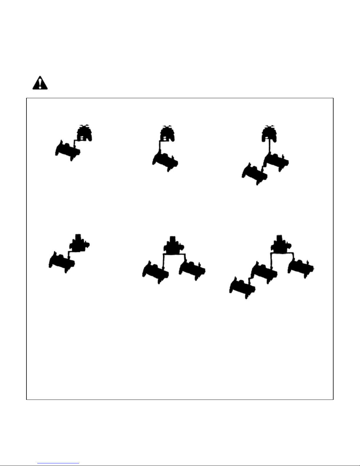
6. If one mower is pulled on both the left and right side of the tow vehicle, then one telescoping
hitch can be mounted to the left and one to the right.

6
Figure 2: Installation of Tow Vehicle Hitch
Figure 3. Assembly of Hitch Pivot and ATV Tongue
C. INSTALLATION OF ATV TONGUE ASSEMBLY (if the lawn and garden hitching was purchased
refer to Section B. Installation of Lawn & Garden Hitching)
1. The tongue can be installed either on the left or right caster assembly depending on how the
wing mower will be towed. See figure 3.Secure the hitch pivot on the chosen caster
assembly with the 1/2” x 3-1/2” hex head bolt, lock washer, and nut provided.
2. Install the tongue into the hitch pivot and secure by placing a 5/16” wire lock pin on each side
of the hitch pivot.
Telescoping Hitch -Install to Left
or to Right or in Both Directions
When Pulling Two Wing Mowers.
Hitch Stop Angle
Adjust Stop Bolt to
Back of Tow Vehicle
Screw Pin
Shackle Clevis
Offset Tongue Position
Direct Behind Tongue Position
Hitch Pivot – Attach
to either Left or Right
Caster Assy.
Tongue

7
D. INSTALLATION OF OPTIONAL HITCHES
1. When a long tongue is needed, remove the tongue pivot angles and spacer from the tongue
assembly and attach to the tongue extension. See figure 4.Slip the tongue in between the
two flats on the tongue extension and secure with 1/2” x 3-1/2” hex head bolts, lock washers,
and nuts provided.
2. When a second mower is pulled behind the first mower in tandem, then the rear hitch
assembly can be installed on the rear cross brace tube. See figure 4. Remove the four 1/2” x
3-1/2” bolts from the rear hitch assembly and position the rear hitch in the desired location on
the cross brace tube. Insert the four 1/2” x 3-1/2” bolts from the bottom up and place the
clamping flat on the top. Secure the bolts with the lock washers and the nuts. Tighten down
appropriately to prevent unwanted loosening.
Note: The long tongue assembly (Part # 900136) and rear hitch assembly (Part # 900137)
must be ordered separately.
Figure 4: Long Tongue Assembly and Rear Hitch Assembly
OPERATIONS AND ADJUSTMENTS
This safety alert symbol is used to indicate safety instructions. Follow
these instructions to avoid personal injury and/or property damage. Read
and follow all instructions in this manual and the included engine manual.
WARNING: Do not allow anyone to operate this equipment who has not fully read and
comprehended the safety manual and who has not been properly trained in the safe
operation of the equipment.
WARNING: Operator should be familiar with all functions of the unit.
Long Tongue Extension
Tongue Pivot Angle
Spacer
Short Tongue
Rear Hitch Assembly
Attach to Rear
Cross Brace Tube
Clamping
Flat

8
A. HITCH CONFIGURATIONS (Refer to Figure 5)
WARNING: Shut off the engine and allow the mower blades to come to a complete stop
before adjusting the spreader hitch on the tow vehicle.
Figure 5: Wing Mower Towing Suggestions and Required Hitches
Tow Vehicle without a Mower Deck
Tow Vehicle with a Mower Deck
1 & 2 combined
or 5
1, 2, & 3 combined
or 5
2 & 4
combined
2 & 3
combined
1 & 2 combined
or 5
1, 2, & 3
combined
1 & 2
combined
2 & 4
combined
1, 2, & 3
combined
1 & 2
combined
Listed above are all of the possible configurations of the wing mowers. The
numbers listed below each wing mower correspond to the hitch or combination of
hitches required to complete that possible configuration.
1. Tow Vehicle Hitch (Telescoping Hitch)
2. Short Tongue
3. Long Tongue Extension
4. Rear Hitch Assembly
5. ATV Tongue Assembly

9
The hitching system is designed so that the wing mower can be pulled directly behind a tow
vehicle without a mower deck or as a left or right wing mower when towed behind a tow vehicle
with or without a mower deck.
If more than one wing mower is towed, they can be pulled in tandem or one on the left and one on
the right or a combination of the above conditions until the desired cutting width is obtained.
CAUTION: Do not operate two wing mowers in tandem on slopes greater than 25% (1 foot
rise, 4 foot run). This can create an unstable condition where the rear wing mower could
push the front wing mower sideways.
When mowing large open areas, adjust the spreader hitch on the tow vehicle so that the wing
mower tongue center line aligns with the outside cut line on the tow vehicle mower. When
trimming around objects or mowing contours, it is best to adjust the tow vehicle hitch in to
eliminate skips. The spreader hitch can be adjusted in and out to get the desired overlap to fit
your mowing job.
B. ATV TONGUE CONFIGURATIONS (Refer to Figure 5)
WARNING: Shut off the engine and allow the mower blades to come to a complete stop
before adjusting the tongue.
WARNING: When attaching the tongue to the back of the tow vehicle, tighten the screw
pin shackle clevis firmly. Property damage or bodily injury may occur if the screw pin
shackle clevis unturns and the wing mower becomes unattached from the tow vehicle.
The hitching system is designed so that the wing mower can be pulled directly behind a tow
vehicle without a mower deck or as a left or right wing mower when towed behind a tow vehicle
with or without a mower deck.
Note: When pulling the wing mower directly behind, it is most maneuverable when the hitch
pivot is fastened on the left carrier arm. See Figure 3.When pulling the wing mower in
the offset position, it is most maneuverable to have the hitch pivot fastened on the right
carrier arm. See Figure 3.
The tongue is designed to adjust from left to right within the hitch pivot. This allows the wing
mower and tow vehicle, with a mower deck, to have proper overlap. Overlap is more critical in
tight areas where a lot of maneuvering is required. This overlap will eliminate most skips between
the tow vehicle and wing mower. In large open areas the overlap is not as critical and should be
adjusted to the user’s preference.

10
C. ADJUSTING CUTTING HEIGHT
WARNING: Shut off all engines and allow the mower blades to come to a complete stop
on the wing mowers and on the tow vehicle before adjusting the cutting height.
The mower deck must first be leveled from front to back before the height can accurately be
adjusted. See Figure 6.This is generally a one time adjustment that should not need to be
performed again.
Adjust the levelness of the mower deck as follows:
1. Pull the mowing unit on to a smooth, level surface.
2. Start by measuring the front and back deck height directly below the carrier arm on either side.
Each side must be adjusted separately.
3. If a difference in measurement is obtained from front to back, the deck needs to be leveled.
Turn the level adjustment bolt clockwise to raise the rear end and counterclockwise to lower
the rear end.
Note: The rear wheel assy. pivot bolt may need to be slightly loosened to aid in easy
adjustment. After levelness has been achieved, the rear wheel assy. pivot bolt must be
tightened back up.
Figure 6: Leveling the Mower Deck
The cutting height can be adjusted in a range from 1.5" to 5.0". This is accomplished by turning
the height adjust cranks on both sides of the mower. See Figure 7. Turn the cranks clockwise to
raise the mower cutting height and counter-clockwise to lower the mower cutting height.
When more than one mower is used at a time, it is very important to have all the mowers adjusted
as close to the same cutting height as possible to obtain a high quality cutting job.
DANGER: Shut off tow vehicle engine and allow mower blades to stop completely before
attempting to measure the cutting height.
Rear Wheel Assy.
Rear Wheel Assy.
Pivot Bolt
Level Adjustment
Bolt

11
Adjust the mower as follows:
1. Pull the mower on to a smooth, level surface.
2. Adjust the mower evenly from side to side by measuring to the ground from the lower edge of
the mower deck. The desired height will be the distance from the ground to the outside lower
edge of the mower deck plus 5/16”. The mower blade cutting edge is 5/16” above the outside
lower edge of the mower deck.
Note: If the height adjust cranks do not turn easily, the pivot bolts holding the carrier arm
assemblies and height adjust screw may be too tight. Loosen the pivot bolts slightly to
allow easier pivoting. Care should be taken not to loosen the pivot bolts too much or
excess wear and flexing may occur. Greasing the threads may also allow greater ease
in adjustment.
Note: To mow at a 2” cutting height or below, set the anti-scalp wheels in the top hole. To
mow above a 2” cutting height, set the anti-scalp wheels in the bottom hole.
Figure 7: Adjusting Wing Mower Cutting Height
The adjustment crank may unturn due to vibration. This will allow the mower’s cutting height to
change. The crank can be secured by folding it down between the adjustment nut tube and the upper
pivot support. See Figure 8.
Adjust Anti-Scalp Wheels
Under Deck to the Upper or
Lower Cutting Range
Height Adjust Screw
Cutting Height
Measure the Distance
and Add 5/16” to get
Cutting height
Mower Blade
Lower Edge
of Deck
5/16”
Smooth Surface

12
Figure 8: Securing Crank While Not In Use
D. STARTING ENGINE
WARNING: Set parking brake on tow vehicle.
Attach wing mower tongue to tow vehicle.
WARNING: Do not start wing mower unless it is attached to the tow vehicle.
Turn on the fuel shut off valve (red colored rotating knob) located inline on the fuel hose. The off
position on the valve is when the red handle lines up with the “O” symbol.
Set the choke to the desired position.
Start engine and allow engine to warm up.
Set the engine speed at about half throttle and engage the mower blades clutch by pulling
outward on the PTO switch. (The PTO switch is located at the front of the mower deck on the
control panel.)
Note: To help extend the life of the clutch the engine rpm should be placed as low as possible
before clutch engagement. If the engine should stall during clutch engagement, raise
the engine rpm until clutch engagement is possible.
CAUTION: If the mower’s engine dies while in use, remove the wing mower from the
uncut area before attempting to engage the clutch. Inspect the blades for any obstructions
that may prevent blade engagement. Failure to follow these instructions may result in
premature clutch and belt failure or a fire.
Adjust engine speed to full throttle.
CAUTION: The engine full speed setting with mower blades running is 3350 RPM.
Adjustment Crank
Carrier Arm
Adjustment Nut Tube
Upper Pivot Support

13
E. SHUTTING OFF WING MOWER
WARNING: Shift to neutral, disengage power to the mower deck, and set the parking
brake before dismounting the tow vehicle.
Slow the engine speed down and disengage the clutch by pushing inward on the PTO switch.
Allow engine to cool down for a short time before moving the ignition switch to the off position.
Turn off the fuel shut off valve (red colored rotating knob) located inline on the fuel hose. The off
position on the valve is when the red handle lines up with the “O” symbol.
F. MOWER OPERATION
DANGER:Keep hands, feet, hair and clothing away from moving parts.
CAUTION:Clean or replace any safety signs that are not readable or damaged.
WARNING: Remove all objects from the work area that might be picked up and thrown by
the blades.
WARNING: Do not mow when children and others are around.
WARNING: Do not fill fuel tank while engine is running or hot.
WARNING: Keep all safety shields and deflectors in place during operation.
CAUTION: Remove grass build up from under safety shields before each use. Do not
remove safety shields while engine is running. Dry grass build up around belts and
sheaves can cause fires.
WARNING: Shut off engine before disconnecting the wing mower from the tow vehicle or
attempting to move the wing mower by hand.
WARNING: Never carry children or passengers.
WARNING: Do not allow children to operate this machine.
CAUTION: Slow down and watch the ends of the wing mowers when making turns so
objects are not struck and/or run over.
Depending on the number of wing mowers being towed, it is usually more efficient to mow the
large areas first with the full system. Once the large areas are completed, mowers can be
dropped off to mow narrower areas.

14
Backing up with one wing mower is easy. Backing becomes a greater challenge as additional
wing mowers are towed. Avoid backing up by planning ahead. Make loops instead of backing.
WARNING: Look down, to the sides, and behind before and while backing to avoid
backing over something or someone. Care should also be taken while backing so that the
wing mower or mowers do not jackknife and damage hitches.
WARNING: Stop the mower blades on both the tow vehicle and all wing mowers if the tow
vehicle becomes stuck or stops going forward because of loss of traction. Shut off the
engines on the wing mowers before attempting to push or pull the tow vehicle.
CAUTION: Do not turn too sharply when the wing mowers are pulled in tandem or pulled
behind a zero turn mower. Sharp turns can force the mowers into each other causing
damage to the hitches.
Listen to the wing mower engines while mowing. The engines should run free and not work too
hard. Working the engine too hard will cause overheating and premature failure.
Do not allow material to build up on the air inlet to the engine cooling system. If the wing
mowers are towed with one on the left and one on the right side, there will be a lot of material
blowing around the right wing mower engine. Special care should be taken to make sure the
engine is getting enough inlet air. Do not allow the engine cooling fins under the shroud to be
blocked. Air flow over the engine will be restricted causing the engine to overheat.
CAUTION: If the mower’s engine dies while in use, remove the wing mower from the uncut
area before attempting to engage the clutch. Inspect the blades for any obstructions that
may prevent blade engagement. Failure to follow these instructions may result in
premature clutch and belt failure or a fire.
G. DRIVE BELT REMOVAL AND TENSION (See Figure 9)
WARNING: Shut off engine and allow mower blades to stop turning before making any
adjustments or repairs.
Remove the safety shields.
Loosen the nuts on the spring-loaded idler; adjust the nut until the belt can be slipped off the
idler and drive sheaves.
Slip the belt down under the drive sheave and off the blade spindle sheaves.
Install the new belt and adjust the tension as follows:
Adjust the spring-loaded idler springs to a compressed length of 15/16” initially for a few hours
until the belt runs in; then adjust the spring to 1-1/8” to 1-1/4” compressed length.

15
Figure 9: Belt Pattern and Spring Adjustment
H. MOWER BLADE REMOVAL, BALANCING & INSTALLATION
CAUTION: Sharp blades can cause bodily injury if not handled properly.
When removing the blade, it is recommended that a block of wood be placed between the blade
and the underside of the mower deck. This will allow the removal of the blade without the need to
hold the blade by hand.
CAUTION: Always balance the mower blades each time they are sharpened.
Out of balance mower blades cause excess vibrations which lead to premature bearing failures,
bolts coming loose, and overall deterioration of the wing mowers.
CAUTION: Always properly tighten the blade bolts to the specified torque. Failure to do so
can lead to unwanted loosening of the blade and damage to the blade holding saddle.
The Model Pro60K uses the Kunz Engineering Part # (202136) blade bolt. This particular hex
head bolt is a 1/2” – 20NF x 1.00” long, grade 5 and it’s proper torque is 85 ft-lbs.
To ease in the blade installation process, use the same block of wood and method used during
the removal of the blades.
Front
Engine
Initial Spring Length 15/16”
Running Spring Length 1-1/8” to 1-1/4”

16
I. LUBRICATION
There are three lubrication points on the wing mower -- one spring-loaded idler pivot and two
caster wheel pivots. Lubricate at approximately 10 hr. intervals or more often as required in dusty
conditions. Lubricate with a high grade of pressure gun grease.
J. TIRE PRESSURE
To reduce wing mower bounce on rough yards, the front and rear tire pressure can be reduced so
they feel slightly soft (approximately 15 PSI) when they are stepped on.
K. FUSE LOCATION
This particular mower comes equipped with a 10 AMP mini blade type fuse. The fuse is located
behind the ignition switch/control panel in a black rubber inline fuse holder.
L. TRANSPORTATION OF MOWER
When transporting the mowers between jobs turn off the fuel shut-off valve. The fuel shut-off
valve is located below the fuel tank.
M. STORAGE
Turn off the fuel shut off valve (red colored rotating knob) located inline on the fuel hose. The off
position on the valve is when the red handle lines up with the “O” symbol. If the mower is stored
outside, the engine should be covered to prevent water from getting inside the engine during
heavy rainstorms. See the Engine Manual for additional information.
N. EPA EVAPORATIVE COMPONENTS
This mower has been designed and built to meet all current EPA regulations. Any modification to
the fuel tank, fuel lines, vapor hose, fuel cap, roll-over / fuel vapor valve, carbon canister
(California Only) and hose clamps are prohibited. Replacement evaporative components should
be purchased from Kunz Engineering. Any questions about EPA regulations or evaporative
components can be directed to Kunz Engineering Inc. at 815-539-6954.

17
WING MOWER SPECIFICATIONS
Model
Pro60K
ENGINE:
Engine Make Kohler
Engine Model Confidant
Cylinders 2
Cycles 4
Crankshaft Vertical
Engine HP 25
Bore 3.30"
Stroke 2.70"
Displacement 45.60 cubic inches
Oil Capacity 2 U.S. qts.
Crankshaft Dia. 1"
Key Slot 1/4"
Crankshaft Length 3.15"
Threaded Hole in End of Crankshaft 7/16-20
Engine Mounting Bolts 3/8-16 1" Thread Rolling
Starter Electric
Choke Manual
Fuse 10 AMP
MOWER:
Fuel Tank 3 Gal.
Effective Cutting Width 58"
Deck Construction 10 ga. Welded steel
Cutting Height 1.5" to 5"
Height Adjustment 2 Cranks
Anti-Scalp Wheels 4 in front, 2 in rear
(3" O.D. x 1-1/4" wide)
Rear Wheels (Fixed) 2 15/600 x 6
(4 ply Turf Pnuematic)
Front Wheels (Caster) 2 13/500 x 6
(Pnuematic Slick)
Blade Dia. 3-20"
Engine Speed, Blades Running 3350 RPM
CLUTCH TYPE Electric
Size 200 ft-lb
DIMENSIONS
Length 65"
Width 72-1/4"
Height 29"
Weight 560 lbs

18
Item Part # Description Pro60K
1202136 Blade Bolt, .1/2"-20NF x 1.00" 3
2204000 Shoulder Bolt, 1/2" x 1-5/8" Shoulder Length 6
3204015 Eye Bolt (Welded) 2
4222005 Worm Drive Hose Clamp (7-7/8" to 9-1/8" Clamping Dia. 2
5222012 Single Split Collar (1" I.D. x .1/2" Thick) 2
6225000 Compression Spring, 1-1/2"L x 1-3/32" O.D. x .135" Wire dia. 1
7226000 Plastic Wheel, 3" O.D. x 1/2" I.D. x 1-1/4" Wide 6
8226012 Offset Wheel Assy., 15/600 x 6, 4 Ply Turf 2
9226016 Centered Wheel Assy., 13/500 x 6, 4 Ply Slick 2
10 238002 "V" Belt, B Section, 127" O.C. Carlisle/Dayco B124 Super II 1
11 241001 Flat Idler, 4" O.D. x 3/8" Hole 2
12 243015 Precision Sealed Wheel Bearings (2" O.D. x 1" I.D.) 8
13 243010 Plastic Bearing (1-3/8" O.D. x 1.00" I.D., Flange, Nylon) 4
14 258018 Electric Clutch (200 ft-lb, 5" "V" Sheave, 1" Bore) 1
235062 Clutch Cable Assembly (1)
15 258020 Spindle Assy. 3
900046 Spindle Shaft (1) ~
900139 Housing Assy. (With Two Bearings) (1) ~
243003 Bearing (2) ~
600204 Bearing Spacer (3-5/8" Long) (1) ~
241007 Sheave, 5-1/4" (1) ~
16 259001 Offset Mower Blade, 2" Wide, 20" Long, 1/2" Hole 3
17 260004 Roll-Over / Fuel Vapor Valve (Includes Gromet) 1
18 264000 Solenoid 1
19 264003 Hour/Tack Meter 1
20 264005 PTO Switch 1
21 264010 Ignition Switch 1
22 269008 Throttle Control, 46" 1
23 269011 Choke Control, 46" 1
24 275001 Control Panel Decal, Starting Instructions 1
24 275002 Warning Decal General 1
24 275003 Danger Decal, Cut Finger 2
24 275007 Warning Decal, Belt Sheild 2
24 275019 Name Decal, Kunz 1
24 275021 Name Decal, AcrEase 2
24 275023 Name Decal, 60" Finish Cut 2
25 277002 Rubber Grommet 7
26 277035 Gas Cap - Audible Click/Tethered, Non-Venting 1
27 277036 Carbon Canister - 300cc (California Only) 1
28 277040 Fuel Tank, 3 Gal., 3-Layer EPA Certified 1
29 600048 Solenoid Support 1
30 600062 Belt Sheild L.H. 1
30 600063 Belt Sheild R.H. (Discharge Side) 1
31 600146 Crank Arm 2
32 600198 Clutch Stop 1
ACREASE WING MOWER PARTS Pro60K
Table of contents
Other Kunz Lawn Mower manuals

Kunz
Kunz AcrEase MR55KE User manual

Kunz
Kunz AcrEase MR44BE Datasheet

Kunz
Kunz AcrEase C60BE User manual

Kunz
Kunz AcrEase MR44B User manual

Kunz
Kunz AcrEase MR55K Datasheet

Kunz
Kunz AcrEase MR55B User manual

Kunz
Kunz AcrEase MR44V User manual

Kunz
Kunz AcrEase MR55B User manual

Kunz
Kunz AcrEase MR44B Datasheet

Kunz
Kunz AcrEase MR55KEI Datasheet