© Kurth Electronic GmbH, All Rights Reserved
4
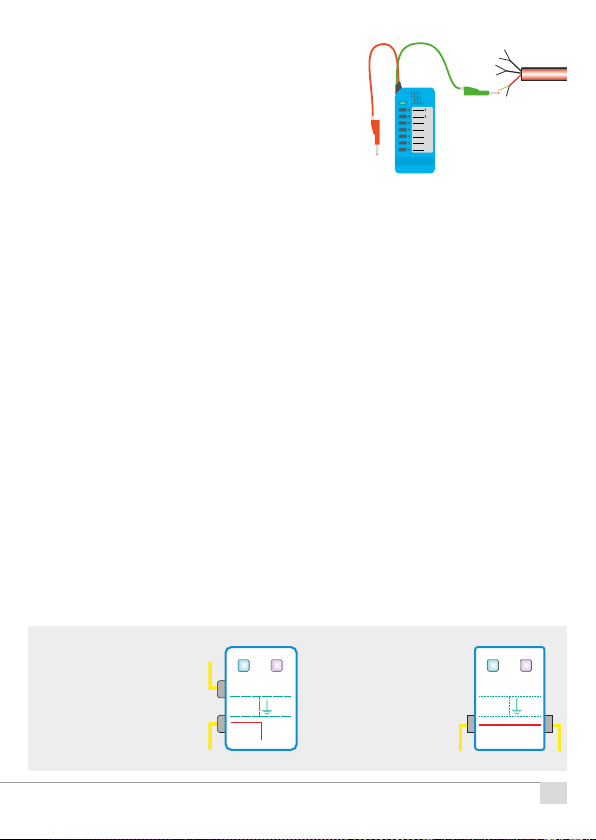
Remote KE905
During the development of the KE905, emphasis was placed on quick and
easy operation. Therefore the KE905 has only two buttons.
On / O
Press the key for > 1 second to switch on the device. The red LOW BATT LED
andthegreenMODELEDlightupbrieyaftertheself-test.ThegreenMODE
LEDthenindicatesthesetting(default)for10seconds,afterwhichitashes
brieyasaswitch-oncheck.Toswitchito,presstheOn/Obuttonagainfor
> 1 second. When the battery voltage drops below approx. 7.5 volts, the red
LOWBATTLEDashesinsteadofthegreenMODELED.
Mode
With this key the search tone and the port can be selected directly on the
Remote KE905. By default, search tone 1 is always sent on port 1.
If the exchange is to be switched through when the line end is known so
that the line is not left without service for the time of the start and departure,
this can be selected by repeatedly pressing the mode key. The exchange is
switched through if port 1 (control port) and port 2 (exchange) are connected.
Press and hold the mode button to select the function or the search tone. The
MODELEDwillthenashattherateshownbelow:
-- Searchtone1onport1–Default
-� Searchtone2onport1
�- Searchtone3onport1
�� Port 1 and Port 2 connected
TheMODELEDashesfor10secondsintheselectedcycleforinformation
purposes.Thentheswitch-oninfosignalisshown.
The mode key is pressed for < 1 second to deter-
mine which function is selected. The LED display
showsthesettingfor10secondsthroughtheas-
hing cycle.
Default setting
IMPORTANT - port 1 is always
the control port from the far end Port 1 Port 4
Tone 1 / 2
Port 2 Port 3
Mode On-Off
GND