Innovation—Environment—People
Telephon Support + 49(0) 81 41 / 95 74 00
5307760 12/2011
1 Safety Advice
Secondary-air appliances interact with the flue gas system
and the fireplace. Therefore you should inform your
responsible building control before installation. The appliance
will only work flawlessly if the installation instructions are
followed. Only a trained expert should take care of the
installation.
2 Range of Use
Approved standard individual fireplaces (example: stoves in
living areas) with vertical flue outlet and external air supply
on the appliances back side.
3 Di ensioning the Supply Air Routing
The dimensioning of the supply air routing has to follow
effective rules, laws, guidelines and norms. In addition to the
air requirement of the fireplace, the secondary-air appliance
has an air requirement of 75 m3/h at Δp 5 Pa or 160 m3/h at
Δp 40 Pa.
4 Installation / Mounting Position
Install the casing pipe vertically on the fireplace. Align the axis
of the secondary-air appliance horizontally (see section 9 / fig.
3, side view and fig. 4, front view). Set the secondary-air
appliance as described in section 5. Now attach the
connection piece to the reception tube. Connect the oval
supply-air duct, e.g. using a flexible aluminium pipe Ø 100
mm, with the supply-air pipe of the fireplace.
5 Setting the Secondary-Air Appliance
The secondary-air appliance should be set to open at the
fireplace's minimum required draught. Please check the
documentation or the type plate of the fireplace for the
required draught. The secondary-air appliance can be
removed from the reception tube for setting. Simply push the
control wheel open and carefully pull the frame. Set the
desired value by turning the two setting weights (see section
5 / fig. 1, Adjusting the Setting Weights) and then lock them
against each other. The measure "a" - 2 corresponds to the
opening value in Pa.
Exa ple: Desired opening value = 14 Pa ➞required measure
"a" = 16 mm.
Afterwards, use light pressure to let the secondary-air
appliance latch back into the reception tube. Make sure it is
aligned correctly as illustrated in section 9 / figure 4, front
view. If the opening value of the secondary-air appliance is set
too low (minimum required draught of the fireplace is not
reached), there will be disruptions of the combustion in the
fireplace!
Kutzner + Weber GmbH
Frauenstrasse 32
D-82216 Maisach
Tel.: +49 (0) 81 41 / 9 57-0
Fax: +49 (0) 81 41 / 9 57-5 00
www.kutzner-weber.de
info@kutzner-weber.de
KUTZNER + WEBER
7 Maintenance / Cleaning
Before the heating period begins, make sure that the
secondary-air appliance can move freely. If dirt or soot
has set on the control wheel, t-piece or the connection
piece, remove it carefully to ensure that the draught
regulator works flawlessly. If necessary, you may
lubricate the bearings with a drop of non-resinous oil
(e.g. sewing machine oil). Do not lubricate or grease the
bearings excessively since this only increases the build-
up of sediments. If the fireplace is used regularly, the
maintenance should be repeated during the heating
period. For this the secondary-air appliance can be
removed, as described in section 5.
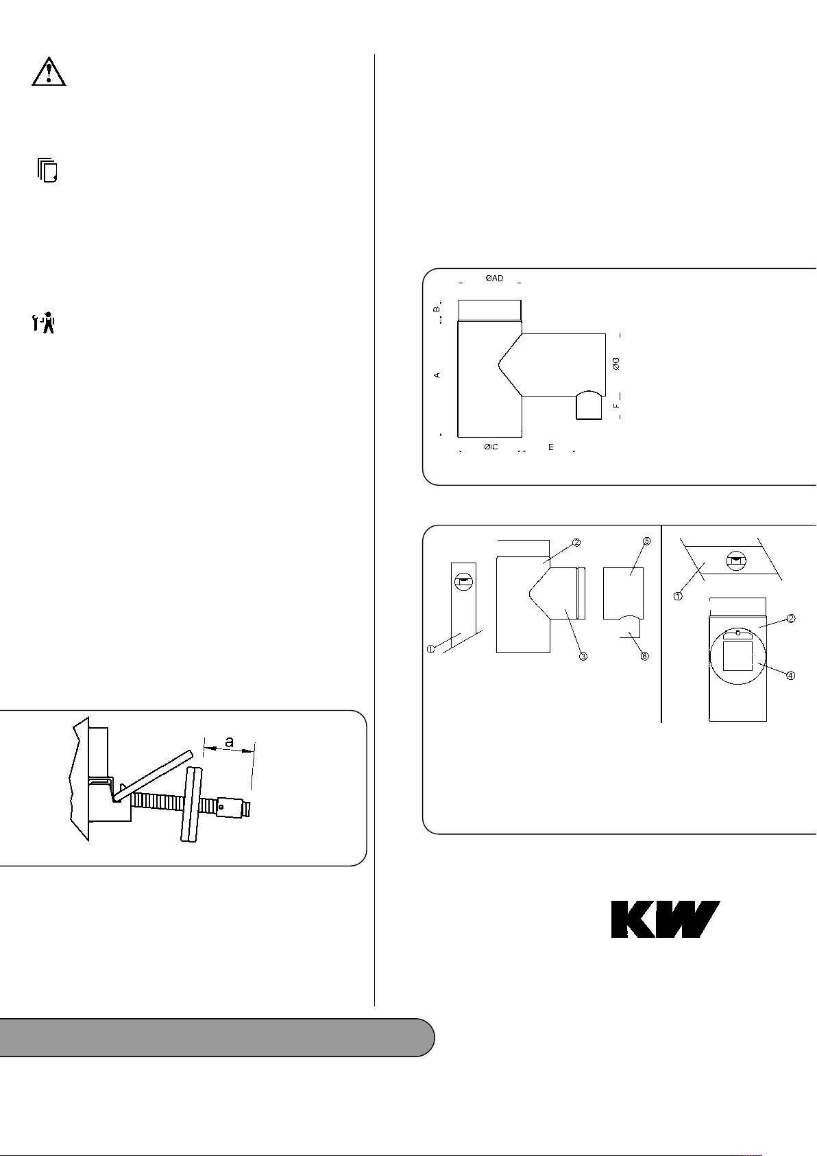
8 Di ensions
Figure 1: Adjusting the Setting Weights
6 Start-Up
After installing and setting the draught regulator you have
to check if a flawless operation of the fireplace is ensured.
In addition, the functionality of the entire flue gas evacuati-
on has to be tested (inspection and cleaning of the flue gas
system must not be impaired). In the case of an accumula-
tion or return flow of flue gasses, these must not escape in
dangerous quantities.
A = 282 mm
B = 48 mm
E = 140 to 190 mm
F = 50 mm
ØAD = 149 (+0 /-1) mm
ØG = ~150 mm
ØiC = 150 (+1/-0) mm
1 = Air level
2 = T-piece
3 = Reception tube
4 = Secondary-air appliance
5 = Connection piece
6 = Supply-air duct
a = Set value
Figure 2: Dimensions
Figure 3: Side view
Figure 4: Front view
9 Figures


