KV2 Audio ESR215 User manual

User Guide
ESR Series
The Future of Sound.
Made Perfectly Clear.
At KV2 Audio our vision is to constantly develop technologies
that eliminate distortion and loss of information providing
a true dynamic representation of the source.
Our aim is to create audio products that absorb you,
place you within the performance and deliver a listening
experience beyond expectations.
· ESR215 · ESR3000
KVV120090-00-07-0_TISK_EN_Guide_ESR3000_ESR215.indd 1 7.11.2015 14:00:34

Important Safety Instructions
1. Read all product instructions.
2. Keep printed instructions, do not throw away.
3. Respect and review all warnings.
4. Follow all instructions.
5. Do not use this unit near water, in un protected out door ar eas or in rain or wet conditions and any
object lled with water cannot be placed on the product.
6. Clean only with dry cloth.
7. Do not block any ventilation openings.
8. Install in accor dance with KV2 Audio‘s recommended installation instructions.
9. Do not install near any heat sources such as heat radiators, heat registers, stoves or other apparatus
that produce heat.
10. Product is designed in Class I. Do not defeat the safety purpose of the grounding type plug.
A grounding type plug has two blades and a third grounding connector. The third connector is
provided for your safety. If the provided plug does not t into your outlet, consult an electrician for
replacement of the obsolete outlet.
11. Protect the power cord from being walked on or pinched, particularly at plugs, conven-ience
receptacles and the point where they exit from the amplier. The AC mains plug or appliance coupler
shall remain readily accessible for operation.
12. Only use accessories specied by KV2 Audio.
13. The unit is intended for use in a 19” rack. Follow the mounting instructions. When a rack on wheels is in
use, use caution when moving the loaded rack to avoid injury from tipping over.
14. Install the product only with both front and rear supports.
CAUTION: Installation should only be done by experienced professionals!
15. Unplug this amplier during lighting storms or when unused for long periods of time.
16. Do not connect an amplier’s output in parallel or series with any other amplier’s output. Do not
connect the amplier output to any other voltage source, such as battery, main source or power
supply, regardless of whether the amplier is turned on or o.
17. Do not run the output of any amplier back into another channels input.
18. Refer all servicing to qualied service personnel. Servicing is required when the amplier has been
damaged in any way, such as when the power-supply cord or plug has been damaged; liguid has been
spilled or objects have fallen into the amplier; rain or moisture has entered the amplier; the amplier
has been dropped; or when for undetermined reasons the amplier does not operate normally.
19. Do not remove top or bottom covers. Removal of the cover will expose hazardous voltages. There are
no user serviceable parts inside and removable may void the warranty.
20. An experienced user shall always supervise this professional audio equipment.
ImportantnovyBEZ.indd 1 7.11.2015 14:17:53

Contents ESR Series
ESR Series
Introduction
Contents
Introduction
2
1
CONTENTS 1
INTRODUCTION ESR SERIES 2
ESR3000 3
ESR215 12
ACCESSORIES 17
Overview 3
Getting started 4
Features - Front panel 5
Features - Rear panel 6
Using the system - Full Range 7
Using the system - Subwoofers 8
Specifications 9
Block diagram 10
Drawing 11
Overview 12
Technology 13
Specifications 14
Frequency characteristics 15
Drawing 16

Contents ESR Series
ESR Series
Introduction
Introduction
2
1
Thank you for purchasing this KV2 Audio, ESR series system, consisting of the ESR3000 stereo controller/
amplifier unit, two ESR215 speakers and optional variants of subwoofers.
The ESR range has been developed for a particular niche in the market, where an all in one box is needed
to give clear detailed reproduction over a wide area. The ESR215 and 212 are three way full range
enclosures with wide dispersion characteristics. They can be used vertically for theatre, church or cultural
centre type installations, or horizontally mounted to give excellent coverage over a tiered seating area for
stadium or grandstand type applications.
Similar to our popular ES range, the ESR cabinets are fully active and driven by a proprietary amplifier,
which delivers equalized, and time aligned accurate signal to each of the components. Two ESR215
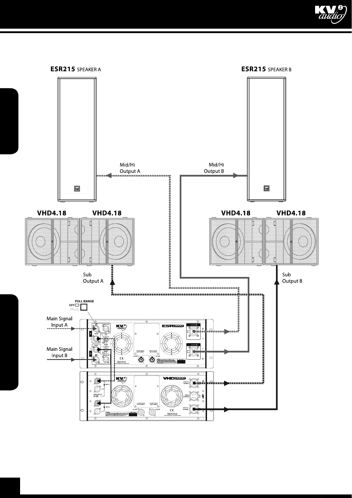
cabinets can be driven by a single ESR3000 High Definition Amplifier, which houses all signal processing
and amplification, as well as providing control for two different external subwoofer cabinet configurations
if required.
In situations where extended bass response is not needed, but full range high definition audio
reproduction with extremely good coverage is required, the ESR Range offers an ideal solution. Economies
of scale are achieved by the requirement of only one ESR amplifier, to run a three way active stereo system
where other systems would require processors and multiple amplifiers to achieve a similar configuration.
This manual contains important information on operating the ESR system correctly and safely. Please take
some time and read this manual to familiarize yourself with the advanced features of this system.
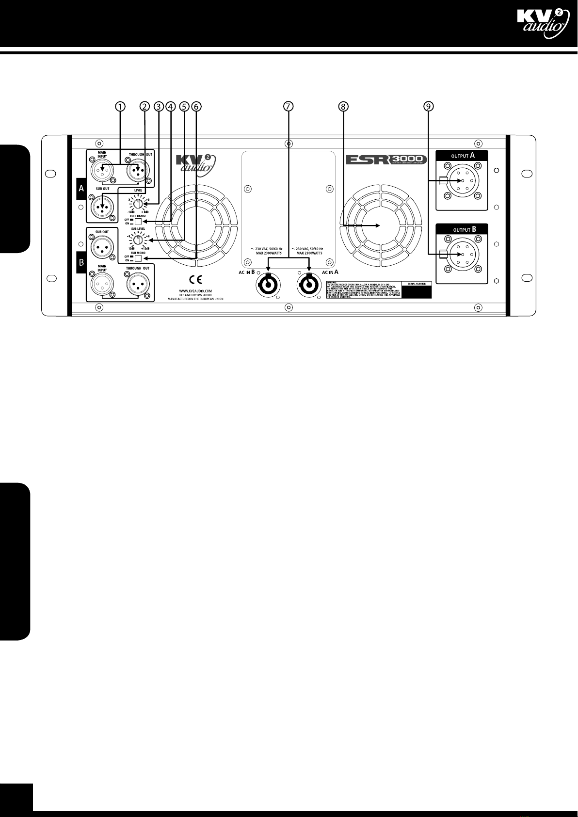
The ESR3000 Amplifier is a three-way, active control and amplification system, specifically designed for
the KV2 Audio ESR series loudspeaker systems. It houses all signal processing and amplification, as well
as providing control for external subwoofer cabinet configurations, and to operate additional subwoofer
cabinets if needed. External subwoofers are powered by the external subwoofer amplifier (VHD3200).
The amplifier compliment and configuration inside the ESR3000 Amplifier is as follows:
High Frequency - 100-watt, Class AB, Push pull, Low intermodulation design.
Mid Frequency - 200-watt, Class AB, Push pull, Low intermodulation design.
Low Frequency - 1000-watt, High-efficiency, Current-enhancing switch mode technology with Linear Active
Filter.
In most cases it would be advisable to use a KV2 Audio Line driver (LD4) in addition at the mixer end, to
ensure that the line to the amplifier is driven correctly and the signal integrity maintained.
Although this system is simple to operate, improper use can be dangerous. This is a very high-powered
device that can put out high voltages and sizeable currents. Always use safe operating techniques with the
SL series system.
FOR YOUR SAFETY, READ THE IMPORTANT PRECAUTIONS SECTION AS WELL AS THE INPUT, OUTPUT
AND POWER CONNECTION SECTIONS OF THIS MANUAL.
Warranty
Your ESR System is Warrantied against defects in material and workmanship. Please refer to your supplier
for more warranty details.
Service
WARNING! Electronic components, risk of SHOCK!
In the unlikely event that your product requires service, it must be returned to an authorized KV2 Audio
distributor, service centre or shipped directly to the factory. All warranty and service repairs must be
undertaken by qualified technical personnel. If the unit/s need to be shipped back to the factory, we advise
using the original packing to reduce the risk of damage in transit.
Please contact your nearest KV2 Audio centre for service details.
Distributors list can be found at www.kv2audio.com.

Overview ESR3000
ESR3000
Getting started
Overview
Getting started
4
3
ESR3000 - 115V part num. KVV 987 275
ESR3000 - 230V part num. KVV 987 276
ESR3000 - 250V part num. KVV 987 277
Applications
Introductions
The ESR3000 Amplifier is three-way, active control and amplification system specially designed for the
KV2 Audio ESR215 full range series loudspeaker systems. It houses all signal processing and amplification
as well as providing control for external subwoofer cabinet configurations if needed, utilizing an external
amplifier. The unit incorporates six amplifiers represented by two 100-watt, Class AB, push pull, low
intermodulation amplifier for high frequencies, two 200-watt, Class AB, push pull, low intermodulation
design for mids and two 1000 watt, high-efficiency, current-enhancing switch mode technology amplifier
for bass. The ESR3000 stereo configuration powers two ESR cabinets accordingly.
•Designed to drive and control the ESR215
•Fixed Installations
Unpacking Amplifier rack mounting
ESR3000 Amplifier Rack mounted
Unpack the ESR3000 Amplifier and check for
any damage. If you find any damage, notify your
supplier immediately. Only the consignee may
institute a claim with the carrier for damage
incurred during shipping. Be sure to save the
carton and all packing materials for the carrier‘s
inspection. Should you ever need to ship the
unit, only use the original factory packaging. If
the shipping carton is unavailable, contact your
supplier to obtain a replacement.
The ESR3000 Amplifier carton should contain:
•ESR3000 Amplifier control unit
•This user guide
•Two PowerCon detachable power cables
The ESR3000 Amplifier is 4 rack units in height
and will mount in standard 19“ rack systems.
Integral rear mounting rack ears are also provided
for additional support, do not rely on fixing and
mounting the amplifier using just the front panel
as support. Use eight screws and washers to
mount the amplifier to the equipment rack rails.
We recommend using a shock mounted rack for
touring use to prolong the life of your amplifier.
Features
•The ESR3000 Amplifier is a stereo, three-way, active control and amplification system specifically
designed for the KV2 Audio ESR Series - ESR215 The Ultimate Full Range System
•Houses all signal processing and amplification as well as providing control for external subwoofer
cabinet configurations.
•External subwoofer is powered by the external subwoofer amplifier (VHD3200).
•The amplifier compliment inside the ESR3000 Amplier is as follows:
-High Frequency - 100-watt, Class AB, push pull, low intermodulation design
- Mid Frequency - 200-watt, Class AB, push pull, low intermodulation design
- Low Frequency - 1000-watt, high-efficiency, current-enhancing switch mode technology with
Linear Active Filter

Overview ESR3000
ESR3000
Getting started
Getting started
4
3
Cooling
AC Requirements
The ESR3000 Amplifier has a comprehensive cooling system featuring chassis sealed PCB board mounting
and shock mounted, speed controlled fans. This means that the cooling system never drives air across PCB
boards, connectors or components, ensuring prolonged electronic component lifespan and minimizing
maintenance cycles.
Air is drawn into the front of the amplifer by the two fans on the rear panel, this passes over the cooling
fans of the heat sinks and exhausts through the rear. If the heat sink gets too hot, its sensing circuit will
open the output relay, disconnecting the load.
It is important to have an adequate air supply at the front of the amplifier, and enough space around the
rear of the amplifier to allow the cooling air to escape. If the unit is rack mounted, do not use doors or
covers on the rear of the rack, the exhaust air must flow without restriction. If you are using racks with
closed backs, use fans on the rear rack panel to ensure an ample air supply.
NOTE: The filters at the top and bottom of the front panel must be kept clean and free of dust and dirt to
allow full operation - CHECK PERIODICALLY.
Two PowerCon cables are provided to connect the ESR3000 Amplifier to a suitable AC power supplies. Each
cable powers each separate amplifier channel for sufficient current delivery.
CAUTION: The ESR3000 requires a ground connection. Always use a grounded outlet and plug.
The PowerCon is a connector without breaking capacity, i.e. the PowerCon should not be connected
or disconnected under load or while it is live. Always isolate your AC supply before disconnecting the
PowerCon connector.
The ESR3000 amplifier operates in either 115V, 230V or 250V modes. Although pre-configured at the
factory, the unit’s operating voltage mode can be changed in the field. Amplifier power plug must remain
readily operable.
Your amplifier will be supplied preset to the voltage used in your area. The table below provides typical
current draw figures for the ESR3000 Amplifier.
The receptacle must be connected to a fuse or circuit breaker. Connection to any other type of receptacle
poses a shock hazard and may violate local electrical codes.
Do not allow water or any foreign object to get inside the amplifier. Do not put objects containing liquid
on or near tne unit. To reduce the risk of overheating the amplifier, avoid exposing it to direct sunlight.
Do not install the unit near heat-emitting appliances, such as a room heater or stove. this amplifier
contains potentially hazardous voltages. Do not attempt to disassemble the unit. The unit contains no user
serviceable parts, repairs should be performed only by factory trained service personnel.
Current draw of ESR3000 Amplifier
AC Input Current draw with amplifier
running at Average Power
(Each Channel)
Current draw with amplifier
running at Peak Power (Each
Channel)
250V 3.2A 5A
230V 3.5A 5.4A
115V 7A 11A

Features ESR3000
ESR3000
Features
Features
Features
6
5
Front Panel
1) AC Mains Switch
The ESR3000 Amplifier has a combination AC Main switch/circuit breaker on the front panel. If the switch
shuts off during normal use, push it back to the ON position once. If it will not stay on you should take the
unit to qualified service personnel to have it serviced.
2) LIMITER
Yellow LED, indicates that the audio limiter has been activated. This RMS limiter protects speakers against
overload.
3) SIGNAL PRESENT
Green LED indicates when audio signal is present at the amplifier input.
4) POWER ON/ THERMAL (AUTO RESET)
Green LED indicates that the AC power is on. When red, it indicates that the thermal limit of the ESR3000
Amplifier has been exceeded and the unit has shut down.
43
1 2

Features ESR3000
ESR3000
Features
Features
6
5
Rear Panel
1) MAIN INPUT / TROUGH OUT
This is the main system input balanced XLR connector with associated Through Signal Output connector
for sending unprocessed signal to other devices in a system.
2) SUB OUT
Balanced XLR output connector, used to connect additional subwoofer. Output is active even when FULL
RANGE switch is ON.
3) INPUT LEVEL ADJUSTMENT
Input Level adjustment potentiometer that allows the user to adjust input levels from -10dB to +8dB.
4) FULL RANGE
Switch, selects the amplifier crossover setup, when ON full range signal is reproduced by ESR215 cabinets,
when OFF signal is by frequency band in conjunction with the subwoofer output setup.
5) SUB LEVEL
This is the level control for the External Sub output in the range -6 to +6 dB.
6) MONO
Switch, sets SUB OUT outputs summing SUB OUT outputs channel A and B together.
7) POWERCON POWER CONNECTORS
The ESR3000 Amplifier uses two connectors per two channel. Each connector supplies one channel. They
accept standard PowerCon terminated AC Mains cables.
8) FANS
The cooling fans operate continuously while the amplifier is on. An internal temperature sensor increases
the speed of the fans during high temperature conditions. Air enters through the front grille and exits
through the rear. Be sure to allow adequate air flow to the front of the rack in which the ESR3000 Amplifier
is mounted.
9) SPEAKER AP6 CONNECTORS
Accepts a standard AP6 terminated loudspeaker cable for connecting up to a single ESR215 cabinet. We
recommend using 2.5mm/core cables.

Using the system ESR3000
ESR3000
Using the system
Using the system
Using the system
8
7
Full range setup
Set ESR3000 Amplifier to FULL RANGE ON mode. ESR215 cabinets plays full range signal.

Using the system ESR3000
ESR3000
Using the system
Using the system
8
7
External subwoofer setup
Set ESR3000 Amplifier to FULL RANGE OFF mode. Signal is crossed over at Hi/Mid for ESR215 cabinets and
SUB for external subwoofer.
SUB SET UP LEVEL setting depends on which subwoofer unit is used.

Specifications ESR3000
ESR3000
Block diagram
Specifications
Block diagram
10
9
Output Channels
Number of Channels 2 (stereo)
Total Output Power 2x 1300W
High Frequency Amplifier Specification
Type Class AB - Push Pull - Low IM Design,
Transformer balanced output
Rated Continuous Power 100W
Operating Bandwidth 2.5kHz to 40kHz
Distortion <0.02%
Rated Continuous Power 100W
Mid Frequency Amplifier Specification
Type Class AB - Push Pull - Low IM Design,
Transformer balanced output
Rated Continuous Power 200W
Distortion <0.02%
Operating Bandwidth 400Hz to 2,5kHz
Low Frequency Amplifier Specification
Type High efficiency, Current-enhancing switch
mode
Rated Continuous Power 1000W
Distortion <0.02%
Operating Bandwidth 20Hz to 400Hz
Signal Input
Input Sensitivity 1.0V RMS
Input Impedance 20kΩ (balanced)
Speaker Output
Speaker Output 2x AP6 female
Power
Power Connector 2x Neutrik PowerCon®
Operating Voltage 115V / 230V / 250V
Operating Voltage Range 100 to 120V@60Hz | 205 to 240V@50Hz |
225 to 260V@50Hz
Recommended Amperage 2x10A 115V | 2x5A 230V | 2x5A 250V
Physical Dimensions
Height 177.8mm (7.0“), 4RU
Width 483mm (19.00“)
Depth 495mm (19.5“)
Weight 39kg (86lbs)

Specications ESR3000
ESR3000
Block diagram
Block diagram
10
9
ESR3000 block diagram
Channel A, channel B is identical

Drawing ESR3000
ESR215
Overview
Drawing
Overview
12
11
410.5
455.3
431.8
481.4
101.7
465.8
37.7
139.3
177
101.7
401.7
37.7
139.3
8.8
7
10.3
R3.5
DETAIL A
DETAIL A
1:1

Description
The ESR215 is a dedicated Full Range System.
Incorporating Patent Pending-Proprietory
components, specifically matched to bespoke
electronics. Exceptionally flat frequency
response and Very High Definition sound
system. Emphasizes every detail and nuance of a
performance and transfers the atmosphere to each
and every audience member
Applications
•Intentionally designed for use in Theatres
and Cultural Centers to provide the
highest audio quality from single Column
enclosures for stage sides and prosceniums
for medium to larger venues
•Fixed Installations
•Music venues
•Classical and opera concerts
Features
•High-output, full-range 3-way loudspeaker
system
•132dB sustained output
•Wide dispersion at high frequencies, controlled
at lowmids to reduce indoor reflections
•Mid/High horn design provides optimized
transducer loading and controlled dispersion
•Patent-Pending 3”diaphragm nitride-titanium
compression driver with complex geometry
phase plug and and neodymium magnetic
motor structure for higher output and lower
distortion performance
•Eight-inch midrange driver with 3”(76mm)
neodymium magnetic motor structure for
increased control and output and decreased
distortion and weight
•Proprietary midrange heat dissipation system
controls voice coil temperature, ensures high
dynamics and extends transducer lifespans
•Front-loaded, 15-inch mid-bass driver with
3.00” (76mm) voice coil assembly and ferrite
magnetic motor structure
•Professional, exterior-grade Baltic birch
construction with wear-resistant polymer
coating Proprietary corner and side handle
designs for simplified handling and carrying
•Acetal copolymer high impact, low friction
feet allowing other cabinets lock-in and easy
cabinet movement
•Six internal corner and one back brace with
M10 suspension points and side and top and
bottom handles with M10 suspension points.
A total of 17 suspension points are available for
custom installation applications
•Requires ESR3000 unit for control electronics
and amplification
ESR Full Range Sound System Benefits
Total flexibility
ESR Series does not require a large number of
speakers. Provides a full range, very high quality
sound from single, small, location. For extended
bass use from a wide range of subwoofers.
Subwoofers can be placed in a large place range,
because of the 70Hz crossover point between ESR
module and subwoofer.
Superb sound
Greater dynamic range than any current active
design. Features Very High Definition technology
with Super Analog amplifier.
Easy set-up
Plug-and-play connection to ESR3000 amp/
processor module. Cabinet features top handles,
seven suspension points and“integral feet” for easy
positioning on stage.
Drawing ESR3000
ESR215
Overview
Overview
12
11
ESR215
The Ultimate, Full Range, Large Scale System
part num. KVV 987 245
FULL RANGE MODULE

The ESR215 is a 3-way high output, active-driven,
full range Loudspeaker module. It is designed as
part of a sound reinforcement speaker system
that includes the ESR3000 system control and
amplification system.
The ESR215 Loudspeaker system benefits from
being designed exclusively to operate above 35
Hz. By optimizing the ideal operating band pass of
each system component, the ESR215 can achieve
extremely high output levels consistently and safely.
Active-driven by the ESR3000 unit
Power, electronic crossovers, phase alignment,
equalization, time correction and speaker
protection are provided within the ESR3000 unit.
This“one plug in, one-plug-out” system ensures fast,
easy set up and complete control. It gives you the
benefits of active sound reinforcement technology,
yet locates the electronics in an easy-access
rackmount module.
Together, the ESR215 and ESR3000 unit deliver the
highest dynamic range of any system currently
available, providing new levels of clarity, depth and
resolution.
Advanced compression driver
KV2 Audio’s transducer partner, 18 Sound in
Cavriago, Italy, manufactures and co-develops all
ESR215 components. The compression driver is a
3-inch nitride-titanium diaphragm design, featuring
a complex geometry phase plug that dramatically
lowers distortion, eliminates ring modes and
provides clearer, ripple free performance.
Wide dispersion horn
The ESR215 features a mid/high integrated horn
design with a number of unique features. The horn
design is based on constant directivity geometry
with an emphasis on maintaining low transducer
compression ratios, high output and wide
dispersion (110˚ x 40˚). The midrange speaker with
precisely designed heat sink midrange “chamber”.
The combination provides optimal cone loading
and heat dissipation. Further loading and dispersion
is controlled through A precision phase plug.
Heat-resistant midrange
Midrange frequencies between 400Hz and
2.5kHz are reproduced by eight-inch midrange
speaker that provides 108 dB of sensitivity (1
watt / 1 meter) when coupled with the integrated
horn. The magnetic motor assembly features
a high temperature 3” (76mm) diameter voice
coil assembly and extensive use of neodymium.
Because of the limited linear movement of most
midrange transducers - usually 2-3mm - ventilation
of the voice coil assembly and magnetic structure
is poor and failure rate from heat fatigue is high.
The ESR215 midrange dissipates heat passively
through the use of a massive heat sink midrange
chamber. When combined with the ESR3000 unit
control electronics, the system provides high output
levels safely and consistently over infinite periods
of time and dramatically reducing heat associated
transducer problems such as power compression
and decreased dynamics.
Neodymium bass transducer
The ESR215 features a fifteen-inch ferrite bass
speaker with front loaded bass reflex design. Great
advantage of the ferrite structure is long-term
stability of parametres and relative resistances to
high temperatures.
The ESR215 bass transducer reproduces frequencies
from 35Hz to 500Hz. The bass transducer is very
precise and fast with high sensitivity. The high
efficiency ferrite motor provides an extraordinary
amount of force that delivers complete control of
the cone mass and a high overall weight loss.
Easy to set up
The ESR215 is an aesthetically pleasing - looking
enclosure featuring a number of ergonomically
designed components that make speaker easy to
set up and use.
ESR215 features the two top handles for pick up and
reposition with additional M10 suspensions point.
There are six industrial grade, internal braces
placed at each corner and one internal brace on
the back. Corner braces are held in places by two
M10 bolts, the back brace is held by two M6 and
one M10, providing a wide range of installation and
suspension flexibility.
Technology ESR215
ESR215
Technology
Technology
Specifications
14
13
ESR215 rear panel
Cable connection to ESR3000 unit
Amplifier/Controller

Technology ESR215
ESR215
Technology
Specifications
14
13
System Acoustic Perfomance
Max SPL Long-term 132dB
Max SPL Peak 135dB
-3dB Response 35Hz to 22kHz
-10dB Response 28Hz to 28kHz
Crossover Point 400Hz, 2.5kHz
High Frequency Section
Acoustic Design Horn Loaded
High Horn Coverage Horizontal / Vertical 110° x 40°
Rotatable Horn NO
Sensitivity 110dB
High Frequency Amplifier Requirement 100W from ESR3000 Amplifier
Throat Exit Diameter / Diaphragm Size 1.4“ / 3“
Diaphragm Material Nitride Titanium
Magnet Type Neodymium
Mid Range Section
Acoustic Design Horn Loaded
Mid Horn Coverage Horizontal / Vertical 110° x 40°
Rotatable Horn NO
Sensitivity 108dB
Midrange Amplifier Requirement 200W from ESR3000 Amplifier
Woofer Size / Voice Coil Diameter / Design 8“ / 3“ / Trans Coil
Diaphragm Material Epoxy Reinforced Cellulose
Magnet Type Neodymium
Low Frequency Section
Acoustic Design Front Loaded, Bass Reflex
Sensitivity 102dB
Subwoofer Amplifier Requirement 1000W from ESR3000 Amplifier
Number of Drivers 2
Woofer Size / Voice Coil Diameter / Design 15“ / 3“ / Inside Outside
Magnet Type Ferrite
Diaphragm Material Epoxy Reinforced Cellulose
Speaker Input
Speaker Input Amphenol AP-6 male
Speaker Output
Speaker Output -
Cabinet
Cabinet Material Baltic birch
Handles 4
Color „Orange peeled“ Matt Black or any RAL
Physical Dimensions
Height 1515 mm (59.65“)
Width 470mm (18.50“)
Depth 500mm (19.69“)
Weight 71kg (156.53lbs)

Freq. characteristics ESR215
ESR215
Drawing
Frequency characteristics
Drawing
16
15
Frequency response
Horizontal Polarpots
Vertical Polarpots
50 Hz - 200 Hz, 6 dB/div
500 Hz - 2 kHz, 6 dB/div
4 kHz - 16 kHz, 6 dB/div
0
30°
60°
90
°
120°
150°
180°
-150°
-120°
-9
0°
-60°
-30°
0
30°
60°
90
°
120°
150°
180°
-150°
-120°
-9
0°
-60°
-30°
30°
0°
60°
90
°
120°
150°
180°
-150°
-120°
-9
0°
-60°
-30°
0
30°
60°
90
°
120°
150°
180°
-150°
-120°
-9
0°
-60°
-30°
0
30°
60°
90
°
120°
150°
180°
-150°
-120°
-9
0°
-60°
-30°
0
30°
60°
90
°
120°
150°
180°
-150°
-120°
-9
0°
-60°
-30°
50 Hz
100 Hz
200 Hz
50 Hz
100 Hz
200 Hz
500 Hz
1 kHz
2 kHz
500 Hz
1 kHz
2 kHz
4 kHz
8 kHz
16 kHz
4 kHz
8 kHz
16 kHz

Freq. characteristics ESR215
ESR215
Drawing
Drawing
16
15
The three-way, mid / high loudspeaker system shall
incorporate two 15-inch mid-bass (MB) transducer
a 8-inch mid range (MR) speaker and a 1.4-inch exit
compression driver high frequency (HF) transducer.
The LF drivers shall be mounted above and below
mid / hi horn tuned for optimum mid-bass response
and dispersion. The HF and MR transducers shall be
loaded on a integrated, constant directivity, wide
dispersion mid/high horn assembly.
The system has a nominal coverage pattern of
110° (horizontal) x 40° (vertical). The loudspeaker
enclosure shall have a rectangular shape and
shall incorporate, two top handles. Enclosure
incorporates M10 suspension points, three M10
suspension points on the top, one in the handles,
three M10 on the bottom and one M10 suspension
point on the back. The speaker cabinet shall be
finished with an ultra wear resistant black polymer
coating and fitted with a weather resistant
perforated steel grill. The system shall receive power
from a separate ESR3000 Amplifer.
ESR3000 Amplifier - Controller module consisting of
separate power amplifiers for high, midrange and
midbass transducers as well as signal processing
including electronic band pass crossover filters,
phase alignment, time correction, equalization
and speaker protection. The speaker system shall
connect to the Amplifier/Controller Module via
proprietary cables terminated in Amphenol AP-6
connectors. The three-way mid / high loudspeaker
system shall be the KV2 Audio ESR215.
ESR215 Architects and Engineer’s Specifications

Accessories ESR Series
ESR Series
Accessories
Accessories
Accessories
18
17
Horizontal Bracket ESR215 Vertical Bracket ESR215
part name:
Horizontal Bracket ESR215
part number:
KVV 987 321
description:
- for ESR215 flying
- 2 pcs M10 T-GRIP
- 2 pcs SMALL HANDLE BRACKETS
- 1 pcs 5mm ALLEN KEY
part name:
Vertical Bracket ESR215
part number:
KVV 987 292
description:
- for ESR215 flying
- 3 pcs M10x40 HEX BOLTS
- 1 pcs 6mm ALLEN KEY
Mid/Hi speaker cable MH15 Mid/Hi speaker cable HM60
part name:
Cable MH15
part number:
KVV 987 147
description:
- 6 wire speaker cable
- AP6 connectors
- 1,5m (5ft) length
- daisy-chaining
- Mid/Hi Module connection or for Mid/Hi Module
part name:
Cable MH60
part number:
KVV 987 125
description:
- 6 wire speaker cable
- AP6 connectors
- 6m (20ft)
- Mid/Hi Module hook-up
Mid/Hi speaker cable HM120 Mid/Hi speaker cable HM180
part name:
Cable MH120
part number:
KVV 987 126
description:
- 6 wire speaker cable
- AP6 connectors
- 12m (40ft) length
- for Mid/Hi Module hook-up
part name:
Cable MH180
part number:
KVV 987 127
description:
- 6 wire speaker cable
- AP6 connectors
- 18m (60ft) length
- Mid/Hi Module hook-up
Cable KIT Amphenol AP6 connector
part name:
CABLE-KIT
part number:
KVV 987 047
description:
- 2 pcs LF15
- 1pc LF40
- 1pc MH60
- consist of four
- high-quality Amphenol AP cable assemblies
part name:
AP-6-11
part number:
KA031
description:
- female
- cable mount
Amphenol AP6 connector Amphenol AP6 connector
part name:
AP-6-12
part number:
KA033
description:
- male
- cable mount
part name:
1m - round flexible speaker cable,
cross section 6 x 2.5mm
part number:
WX 004

Accessories ESR Series
ESR Series
Accessories
Accessories
18
17
RECOMMENDED SPEAKER CABLE LENGTHS
KVV120090-00-05-0-ESR3000,ESR215_ENG-obsah.indd 19 7.11.2015 13:41:09
This manual suits for next models
6
Table of contents
Other KV2 Audio Stereo System manuals