KYLAND Technology KOM300M Assembly instructions

KOM300M User’s Manual 201110
1
KOM300M
Industrial Media Converter
Hardware Installation Manual
Kyland Technology Co., LTD.
Publication Date: Oct. 2011
Version: V1.0
Customer Service Hotline: (+8610) 88796676
FAX: (+8610) 88796678
Website: http://www.kyland.cn
No.: 1.12.02.2009-0

KOM300M User’s Manual 201110
2
KOM300M Industrial Media Converter
Hardware Installation Manual
Disclaimer: Kyland Technology Co., Ltd. tries to keep the content in this manual as accurate and
as up-to-date as possible. This document is not guaranteed to be error-free, and we reserve the
right to amend it without notice to users.
Copyright © 2011 KYLAND Technology CO., LTD.
All rights reserved.
No part of this documentation may be excerpted, reproduced, translated, annotated or duplicated,
in any form or by any means without the prior written permission of KYLAND Corporation.

KOM300M User’s Manual 201110
3
Notice for Safety Operation
This product performs reliably as long as it is used according to the guidance. Artificial
damage or destruction of the equipment should be avoided.
zRead this manual carefully and keep it for future reference;
zDo not place the equipment near water sources or damp areas;
zDo not place anything on power cable or put the cable in unreachable places;
zDo not tie or wrap the cable, which may cause a fire risk.
zPower connectors and other equipment connectors should be firmly interconnected
and checked frequently.
zDo not repair the equipment by yourself, unless it is clearly specified in the manual.
zPlease keep the equipment clean; if necessary, wipe the equipment with soft cotton cloth.
In the following cases, please immediately remove power and contact your Kyland
representative:
zWater gets into the equipment;
zEquipment damage or shell breakage;
zEquipment operation or performance has abnormally changed;
zThe equipment emits odor, smoke or abnormal noise.

KOM300M User’s Manual 201110
4
Contents
1. Packing List..............................................................................................................................5
2. Product Overview.....................................................................................................................5
3. Structure and Interface.............................................................................................................5
3.1 Front Panel ........................................................................................................................5
3.2 Top Panel...........................................................................................................................6
4. Mounting ..................................................................................................................................6
4.1 Dimension Drawing ...........................................................................................................6
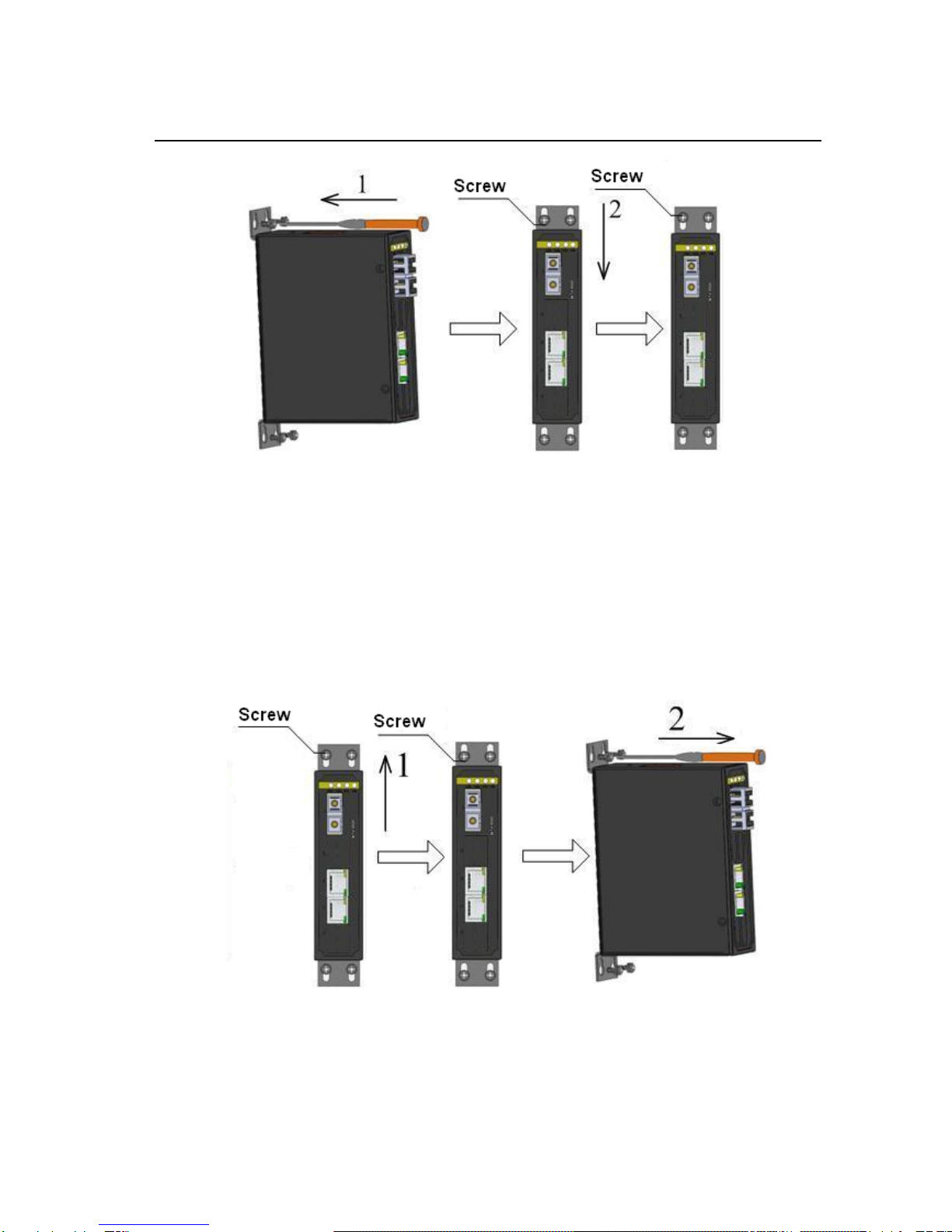
4.2 Mounting Steps..................................................................................................................8
5. Cable Connection...................................................................................................................10
5.1 10/100Base-T(X) Ethernet port........................................................................................11
5.2 100Base-FX Ethernet Port...............................................................................................12
5.3 Power ..............................................................................................................................13
5.4 Grounding........................................................................................................................14
6. LED Indicators........................................................................................................................15
7. Management access ...........................................................................................................16
7.1 Connected through Ethernet cable ..................................................................................16
7.2 Web interface ..................................................................................................................18
8. Product Models ......................................................................................................................18
9. Basic Features and Specifications .........................................................................................19

KOM300M User’s Manual 201110
5
1. Packing List
KOM300M Industrial Media Converter 1
Hardware Installation Manual 1
CertificateofQuality(includingWarrantyCard) 1
Note: After unpacking, please check the accessories and the appearance of the equipment. If
anything is missing or damaged, please contact us.
2. Product Overview
KOM300M is a series of green low power consumption DIN-Rail industrial media
converter that can be applied extensively in wind power, distribution network
automation, subway PIS, power SCADA, wastewater treatment, metallurgy,
intelligent transportation, rail transit and many other industries.
KOM300M support telnet and web management methods, Kyvision centralized
management, FTP/TFTP upgrade, and support SNMPv1/v2/v3, LLDP, HTTP,
Modbus and TCP.
KOM300M industrial media converter supports DIN-Rail and panel mounting, and
supports IP40 protection class. It provides one 100Base-FX port and two
10/100Base-T(X) RJ45 ports in the front panel.
3. Structure and Interface
3.1 Front Panel

KOM300M User’s Manual 201110
6
1: PWR1 -- Power 1 LED
2: PWR2 -- Power 2 LED
3: 1 -- 100Base-FX port LED
4: Run-Run LED
5: 1 -- 100Base-FX port
6: (2,3)-- two 10/100Base-T(X) RJ45 ports
7:RJ45 port Speed LED
8:RJ45 port Link/ACT LED
Figure 1 Front Panel
3.2 Top Panel
1: Terminal block for power input
2: Screw for grounding
Figure 2 Top Panel
4. Mounting
4.1 Dimension Drawing

KOM300M User’s Manual 201110
7
zDimension Drawing for DIN-Rail Mounting (Unit: mm)
Figure 3 DIN-Rail Mounting Dimension Drawing
zDimension Drawing for Panel Mounting (Unit: mm)
Figure 4 Panel Mounting Dimension Drawing
Note: The switch housing is a part of the heat dissipation system, which becomes hot during
operation. Please be careful when handling the device during operation.

KOM300M User’s Manual 201110
8
4.2 Mounting Steps
zKOM300M DIN-Rail Mounting
The specific steps are as follows:
Step 1: Select the mounting position for KOM300M and ensure that there is
adequate space.
Step 2: Insert the top of the DIN-Rail into the slot of the DIN-Rail connecting
seat in the rear panel of KOM300M as seen in Figure 5; move the device in
the direction of arrow 2 to put the whole Din-Rail into the seat; verify the
KOM300M is firmly mounted on the DIN-Rail, as shown in Figure 5.
Figure 5 DIN-Rail Mounting
zRemove KOM300M from DIN-Rail
The specific steps are as follows:
Step 1: Insert the screwdriver into the hole at the bottom of spring locking
plate; press the plate down to loosen the connection of DIN-Rail and switch,
as shown in arrow 1
Step 2: Pull the KOM300M up in the direction of arrow 2; meanwhile remove
the device from the DIN-Rail along the direction of arrow 3.

KOM300M User’s Manual 201110
9
Figure 6 DIN-Rail Dismounting
zKOM300M Panel Mounting
The specific steps are as follows:
Step 1: Select the mounting position for KOM300M on the wall or in cabinet;
ensure that there is adequate space for the switch.
Step 2: Drill 4 holes on the selected position according to the panel mounting
dimension drawings; use a cross-screwdriver to screw 4 cross-slot screws
(M3×10) into holes. Don’t tighten the screws completely; leave about 5mm of
space between.
Step 3: Aim 4 mounting holes on KOM300M mounting plate at 4 fixed screws;
pass the screws through 4 holes with the diameter of 6.5mm (Ф6.5); then slide
down KOM300M as seen in arrow 2; finally screw 4 screws tightly. Now the
KOM300M should be firmly fixed to the wall or cabinet.

KOM300M User’s Manual 201110
10
Figure 7 Panel Mounting
zRemove KOM300M from wall or cabinet
The specific steps are as follows:
Step 1: Use a screwdriver to loosen 4 screws; move the device up to let
screws into 4 holes with the diameter of 6.5mm (Ф6.5) as seen in arrow 1.
Step 2: Unscrew the screws from wall or cabinet; remove the device from wall
or cabinet
Figure 8 Panel Dismounting
5. Cable Connection

KOM300M User’s Manual 201110
11
5.1 10/100Base-T(X) Ethernet port
10/100Base-T(X) Ethernet RJ45 port can be connected to terminal equipment and
network devices with straight-through cables or crossover cables. RJ45
connectors must be equipped at both ends of cable.
zPin definition of 10/100Base-T(X) RJ45 port
Pin number of 10/100Base-T(X) RJ45 port is shown in Figure 9
Figure 9 RJ45 Port
Pin definition of 10/100Base-T(X) RJ45 port is shown in Table 1
Table 1 Pin Definition of 10/100Base-T(X) RJ45 Port
Pin MDI-X signal name MDI signal name
1 Receiving data+(RD+)Output data+(TD+)
2 Receiving data-(RD-)Output data-(TD-)
3 Output data+(TD+)Receiving data+(RD+)
6 Output data-(TD-)Receiving data-(RD-)
4, 5, 7, 8 Unused Unused
Note: “+”“-”means level polarity.
zWiring Sequence
Figure 10 10/100M Straight-through Cable Wiring
8 7 6 5 4 3 2 1

KOM300M User’s Manual 201110
12
Figure 11 10/100M Cross-over Cable Wiring
5.2 100Base-FX Ethernet Port
100Base-FX Ethernet port is equipped with FC/ST/SC connector, and each port
consists of TX (transmit) port and RX (receive) port, as seen on the left in Figure
12.
100Base-FX port wiring is shown on the right in Figure 12 (Take SC port as
example; ST/FC wiring method is the same with SC). Connect the TX (transmit)
port of device A to the RX (receive) port of device B, and the RX (receive) port of
device A to the TX (transmit) port of device in order to transmit data between
device A and device B.
Figure 12 100Base-FX Port Wiring

KOM300M User’s Manual 201110
13
Note: A laser is used to transmit signals in fiber cables. The laser meets the requirements of
level 1 laser products. Routine operation is not harmful to your eyes, but do not look directly at
the fiber port or fiber connector when the switch is powered on.
5.3 Power
According to the power input requirements, use a 5.08mm-spacing terminal block
to connect power cable.
Note: The cross section area of power cable is required to be greater than 0.75mm2and less
than 2.5mm2. The grounding resistance requirement: <5Ω.
z5 pin 5.08mm power terminal block
Figure 13 5-pin 5.08mm-spacing Plug-in Terminal Block
5 pin 5.08mm power terminal block contact definition
Table 2 Contact Definition
Contact number DC wiring definition AC wiring definition
1 PWR1: + PWR1: L
2 PWR1: - PWR1: N
3 Protection Ground Protection Ground
4 PWR2: - PWR2: N

KOM300M User’s Manual 201110
14
5 PWR2: + PWR2: L
zWiring and mounting
Step 1: Take the power terminal block off KOM300M
Step 2: Insert the power cable into the terminal block and fix the power cable
Step 3: Put the terminal block back to KOM300M with the connected cable
5.4 Grounding
zChassis grounding and power terminal grounding
Figure 14 Chassis Grounding and Power Terminal Grounding
There is a grounding screw on the top panel of the KOM300M, which is for
chassis grounding. One end of the chassis grounding cable is connected with
the grounding screw and the other end of the cable is reliably grounded. (The
cross section area of chassis grounding cable should be more than 2.5mm2.
The grounding resistance requirement: <5Ω)
The grounding part in the 5.08mm power terminal block is called surge
grounding.
It is required to connect the chassis grounding part with the surge grounding
part by an 18#AWG yellow-green line as seen below
z18#AWG yellow-green line (Unit: mm)

KOM300M User’s Manual 201110
15
Figure 15 18#AWG Yellow-green Line
Note: If KOM300M needs to perform a dielectric voltage withstand test, in order to avoid test
failure, please disconnect the 18#AWG yellow-green line to disable surge protection circuit,
which connects to surge grounding.
Figure 16 Disconnect 18#AWG Yellow-green Line
6. LED Indicators
Table 3 KOM300M LED Indicators
LED State Description
Power LEDs

KOM300M User’s Manual 201110
16
PWR1
ON Power 1 connects and operates normally.
OFF Power 1 disconnects or operates abnormally.
PWR2
ON Power 2 connects and operates normally.
OFF Power2 disconnects or operates abnormally.
Run LED
Run
Blinking CPU is running normally at 1 Hz.
ON CPU is running abnormally or the device is starting.
OFF CPU is not started up.
10/100Base-T(X) RJ45 port LEDs
Speed
(Yellow)
ON 100M working state
OFF 10M working state or no connection
Link/Act
(Green)
ON Effective network connection in the port
Blinking Network activities in the port
OFF No effective network connection in the port
100Base-FX port LED
LINK/ACT
On Effective network connection in the port
Blinking Network activities in the port
Off No effective network connection in the port
7. Management access
Access the switch through the following two ways
7.1 Connected through Ethernet cable
First, connect any port of the device with the Ethernet port of a personal computer
through an RJ45 cable.
Second, open the Run window from the start menu, then input “telnet + ‘IP
address’”. Click “OK” to enter the Telnet interface. The default IP address is
192.168.0.2

KOM300M User’s Manual 201110
17
Figure 17 Enter Telnet
Third, click “OK”, and input a default user name “admin” and password “123” to
enter the Telnet configuration interface, see Figure 18.Type in a CLI command from
Table 4
Figure 18 Telnet Configuration Interface
Table 4 CLI Command

KOM300M User’s Manual 201110
18
View Command Description
User View SWITCH>enable Enter management view
Management View SWITCH#show interface Show the IP address of current device
Management View SWITCH#show version Show hardware and software versions
Management View SWITCH#reboot Reboot
Management View SWITCH#load default Reload factory default settings
Management View SWITCH#config terminal Enter configuration view
7.2 Web interface
First, connect the Ethernet port on the PC to any RJ45 port on the device.
Second, input the IP address of the current device in web browser , default IP is
192.168.0.2. The Web interface access screen will appear as shown below in
Figure 19, login with default user name “admin” and password “123”.
Figure 19 Access Web Interface
8. Product Models
The specific configuration models of KOM300M are shown in below table;
Table 5 KOM300M Configuration Table
Model Description Power

KOM300M User’s Manual 201110
19
KOM300M-1S/M-2T
1 100Base-FX port, SM/MM
ports, FC/SC/ST connector;
2 10/100Base-T(X) RJ45 ports
12VDC, 24VAC/DC, dual
redundant power inputs
The optional accessories of KOM300M are shown in below table;
Table 6 KOM300M Optional Accessories
Model Description
DT-BGAZ-01 Panel mounting kit
DT-FCZ-RJ45-01 RJ45 dustproof shield
9. Basic Features and Specifications
zPower Requirements
Power input: 12VDC (9~18VDC), 24VAC/DC (18~72VDC, 18~50VAC)
Power terminal: 5-pin 5.08mm-spacing plug-in terminal block
Power consumption: full load: 2.6W(MAX)
zPhysical Characteristics
Housing:Metal,fanless
Installation: DIN-Rail or Panel mounting
Dimensions (W×H×D): 30mm×115mm×91.5mm
Weight: 0.3Kg
zEnvironment Limits
Operating Temperature: -40℃to 85℃
Storage Temperature: -40℃to 85℃
Ambient Relative Humidity: 5% to 95% (non-condensing)
zMTBF: 462741hrs
zWarranty: 5 years

KOM300M User’s Manual 201110
20
For more information about KYLAND products, please visit our website:
http://www.kyland.cn/
Table of contents
Other KYLAND Technology Media Converter manuals
Popular Media Converter manuals by other brands

B+B SmartWorx
B+B SmartWorx 232OTTL quick start guide

Texas Instruments
Texas Instruments TMS320 Series user guide

Lika
Lika DRAW WIRE SF0M1 Series manual

Transition Networks
Transition Networks FXC1115T user guide

network
network MR-TR-3G-D15 Series user manual

Delta Electronics
Delta Electronics PMC-24V100W1A Series instruction manual