KYLAND KPS3102 Series User manual

KPS3102 Serial Server User Manual
Issue Date: October, 2020
Version: V1.0
Number: 112028251

KPS3102 Serial Server User Manual
Disclaimer: Kyland Technology Co., Ltd. tries to keep the content of this manual as accurate and as
updated as possible. This document is not guaranteed to be error-free, and we reserve the right to
amend it without notice to users.
All rights reserved.
No part of this documentation may be excerpted, reproduced, translated, annotated or duplicated,
in any form or by any means without the prior written permission of KYLAND Corporation
Copyright © 2020 Beijing Kyland Technology Co.,Ltd.

I
Conents
1 Product Introduction..................................................................................... 1
1.1 Summary..........................................................................................................2
1.2 Package List ....................................................................................................2
1.3 Product Characteristics....................................................................................2
2 Accidence..................................................................................................... 3
2.1 Connect Power Supply.....................................................................................4
2.2 Connect Serial Device......................................................................................4
2.2.1 Set RS-485 terminal resistor......................................................................4
2.2.2 Connect to host or network........................................................................4
2.3 LED indicator ...................................................................................................5
2.4 Dimensions......................................................................................................6
2.5 PIN Definition...................................................................................................6
2.5.1 Network interface(RJ45).......................................................................6
2.5.2 Serial interface(DB9 male)....................................................................7
2.5.3 Power input interface.................................................................................7
2.6 Specification parameters..................................................................................8
3 Web Console Configuration ........................................................................11
3.1 Login..............................................................................................................12
3.2 Device information .........................................................................................12
3.3 Network configuration.....................................................................................13
3.4 Serial server configuration..............................................................................14
3.5 Serial Port Data Statistics...............................................................................15
3.6 Software Upgrade..........................................................................................15
3.7 Restart ...........................................................................................................16
3.8 Exit.................................................................................................................17

1 Product Introduction
1
1 Product Introduction
Welcome to use Kyland KPS3102 serial port server product, this serial port server has the
function of power redundancy, it can realize the conversion between network port data and serial
port data. KPS3102 serial port server has dual power input, serial port built-in 2 KV
electromagnetic isolation protection.
We will introduce KPS3102 serial server product in this section, including the following:
Summary
Package list
Product characteristics

1 Product Introduction
2
1.1 Summary
KPS3102 serial server is a serial port server device with redundant power supply function,
which can realize the conversion between TCP/UDP protocol and RTU protocol. The device
serial port provides 2KV serial port isolation protection, each RS-232/RS-422/RS-485 serial port
can be configured as serial port operation mode and different baud rate separately, and allows
these two types of network to be integrated through one network port of serial port server. The
serial port server will directly convert the data of the network port.
The network port can be configured as TCP Client, TCP Server and UDP modes, and serial
port can choose RS-232/RS-422/RS-485 three modes.
1.2 Package List
KPS3102 includes the following accessories:
•One KPS3102 serial server device
•Installation manual
•CD-ROM
•Qualified certificate
•
Note:
If any of the above items are lost or damaged, please contact the sales representative.
1.3 Product Characteristics
•Realize data conversion between TCP/UDP protocol and RTU protocol
•Two 100Mbps electric ports, one RS-232/RS-422/RS-485 serial port
•15 KV ESD protection circuit at serial port
•2 KV isolation protection at serial port
•Support HTTPS, SSH2 security configuration protocol
•Support redundant 12~48 Vdc power input
•Support one-click recovery
•IP40 protection class
•CE,FCC,UL61010,C1D2,RoHS certifications

2 Accidence
3
2Accidence
We will provide KPS3102 serial server basic operation instructions for installation in this
chapter, including the following:
Connect power supply
Connect serial device
RS-485 terminal resistor
Connect to host or network
LED indicators
Dimension
Pin definition
Network interface (RJ45)
Serial interface (DB9 male)
Power supply input interface
Specification parameters

2 Accidence
4
2.1 Connect Power Supply
KPS3102 serial server connect power supply through terminal block.
Connect power supply
1. loosen or remove the screws on the power terminals;
2. Connect 12-48VDC power cord to power terminals;
3. Tighten the screws on the power terminals.
Caution:
The serial server device has no power switch. When there is a power input, the device
immediately starts to run, and the power indicator on the front panel of the device will shine. The
serial port server device has two redundant DC power input.
2.2 Connect Serial Device
The serial port of the serial server device is located on the front panel of the device. To
connect multiple devices to the network, note the following
1. all devices are connected to a single serial port, the same protocol must be used;
2. each master device on the serial server device must be connected to its own port.
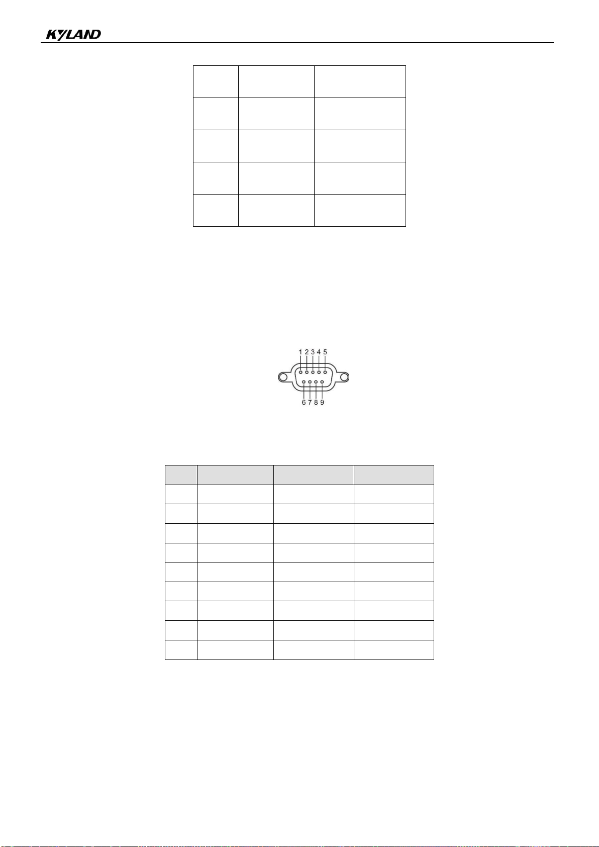
3. Serial port PIN description please refer to section 2.5: pin definition.
2.2.1 Set RS-485 terminal resistor
If you use RS-485 transmission mode in a relatively harsh environment, you may need to
increase the terminal resistance to prevent the reflection of serial signals. KPS3102 serial server
serial port default pull Up/down resistor is 120 KΩ. The DIP switch on the top panel of the serial
server for each serial port is used to enable/disable RS-485 120Ω terminal resistors.
Set 120Ω terminal resistor: DIP switch identification 1 corresponds to serial port S1. When
the DIP switch to the ON, the terminal resistor of the corresponding serial port is enabled; when
the DIP switch to the OFF, the terminal resistor of the corresponding serial port is disabled; and
the terminal resistor is disabled by default.
2.2.2 Connect to host or network
KPS3102 serial server has one 10/100Mbps network port, it is located in the front panel of
the serial server device. When the serial server works normally, it can be connected to the
network directly using the network cable. When initialization and fault detection are required, the
PC can be connected directly through the network cable. When the serial port server is running,

2 Accidence
5
the two green LEDs on the network port will shine, so as to determine whether the serial port
server has been connected to the network and the rate of access to the network.
KPS3102 serial server has a network port and a mac address, users can change the IP
address, mac address cannot be changed.
2.3 LED indicator
Table 1 Panel operation and indicator status
Item
Description
Reset button
Press Reset button for 5 seconds, the serial server device will restart and return to
factory configuration.
LED indicator
PWR1, PWR2
Green
ON: the corresponding input power supply is connected and
running normally
OFF: power supply does not connect or running abnormally
Run
Green
Flashing: Main board and CPU system running normally (1 Hz
frequency)
ON: device power-up process
OFF: device no power
E1(Link/ACT)
Green
ON: The port has established an effective network connection
Flashing: Port is active
OFF:The port has not established an effective network
connection
E1(10/100M)
Yellow
ON: 100M working status (100Base-TX)
OFF: 10M working status (10Base-TX) or no connection
E2(Link/ACT)
Green
ON: The port has established an effective network connection
Flashing: Port is active
OFF:The port has not established an effective network
connection
E2(10/100M)
Yellow
ON: 100M working status (100Base-TX)
OFF: 10M working status (10Base-TX) or no connection
S1-T
Green
Flashing: Serial port 1 is sending the data signal
OFF: serial port 1 no data transmission
S1-R
Green
Flashing: Serial Port 1 is receiving data signal
OFF: serial port 1 no data transmission

2 Accidence
6
2.4 Dimensions
Figure 1 KPS3102 (unit: mm)
2.5 PIN Definition
2.5.1 Network interface(RJ45)
Figure 2 RJ45 wire number
Table 2 RJ45 wire definition
Pin
MDI-X Signal
MDI Signal

2 Accidence
7
1
Rx+
Tx+
2
Rx-
Tx-
3
Tx+
Rx+
6
Tx-
Rx-
4,5,
7,8
No definition
No definition
2.5.2 Serial interface(DB9 male)
KPS3102 serial server uses DB9 serial port interface to connect to serial device. Each serial
port supports three serial interfaces: RS-232, RS-422, RS-485, it can be selected by software
Figure 3 DB9 wire number
Table 3 DB9 wire definition
Pin
RS-232
RS-422
RS-485
1
CTS
RxD-(B)
-
2
RxD
RxD+(A)
-
3
TxD
TxD-(Z)
Data-(B)
4
RTS
TxD+(Y)
Data+(A)
5
GND
GND
GND
6
–
–
7
–
–
8
–
–
9
–
–
–
2.5.3 Power input interface
KPS3102 serial server uses a plug-in terminal with 5.08 mm spacing to connect the power
supply, with dual power input PWR1 and PWR2.

2 Accidence
8
Figure 4 Power input
表4
Power
PIN
Description
PWR1
+/L
PWR1 connect to positive
-/N
PWR1 connect to negative
PWR2
+/L
PWR2 connect to positive
-/N
PWR2 connect to negative
2.6 Specification parameters
Network interface
Network interface: 2
Rate: 10/100Mbps, Auto MDI/MDIX
Connector: RJ45×1
Protocol: TCP/UDP
Isolation Protection: Built-in 1.5KV
Serial interface
Serial interface: 1
Serial type: RS-232/RS-422/RS-485, Software is optional
Connector: DB9 male
ESD protective: 15KV ESD
Isolation Protection: 2KV
DIP: enable/disableRS-485 with 120Ω terminal resistor.
Serial communication parameters
Data bit: 7, 8
Stop bit: 1, 2
Parity: None、Even、Odd、Space、Mark
Flow control: XON/XOFF、RTS/CTS、None
baud rate: 300bps~460.8kbps

2 Accidence
9
Serial signal
RS-232: TxD, RxD, RTS, CTS, GND
RS-422: Tx+, Tx-, Rx+, Rx-, GND
RS-485: Data+, Data-, GND
Software
Security configuration protocol: HTTPS、SSH2
LED indicator
System: PWR1, PWR2, Run
Serial port: S1-T/R
Network: SPEED,ACT/LINK (RJ45)
Button
Reset: support “recovery factory configuration”
Mechanical
Enclosure: Aluminum
Weight: 165g
Dimension: 30×115×68 mm (1.8×5.3×7.3 in)
Protection class: IP40
Mounting: DIN
Environment
Operating temperature: -40℃~75℃
Storage temperature: -40℃~85℃
Relative humidity: 5~95% no condensation
Power requirement
Input voltage: 24VDC (12-48VDC)
Terminal block: 4-pin 5.08 mm spaced plug terminal block
Consumption: 1.8W
Overload protection: Support
Reverse protection: Support
Redundant Power: Support
Industry standards
Certifications: CE, FCC, UL61010, C1D2, RoHS
EMI: EN 55032 Class A
FCC Part 15 Subpart B Class A

2 Accidence
10
EN 55024
EMS: IEC61000-4-2(ESD): ±6kV(contact), ±8kV(air)
IEC61000-4-3(RS): 10V/m (80MHz–2GHz)
IEC61000-4-4(EFT): Power Port: ±2kV; Data Port:±1kV
IEC61000-4-5(Surge): PowerPort: ±1kV/DM, ±2kV/CM; Data Port:±1kV
IEC61000-4-6 (CS): 10V(150KHz-80MHz)
Mechanical standards:
Vibration: IEC60068-2-6
Impact: IEC60068-2-27
Free fall: IEC60068-2-32
Warranty
Warranty: 5 years

3 Web Console Configuration
11
3 Web Console Configuration
KPS3102 serial server has a web page, can open the web page through the browser to set
the serial server device, such as Firefox browser, IE browser. in this chapter, we will introduce
web console function groups and function definitions.
This chapter includes the following:
Login
Device information
Network configuration
Serial server configuration
Software upgrade
Restart
Exit

3 Web Console Configuration
12
3.1 Login
Connect to KPS3102 serial server web console: open the browser and
enter the IP address of the device.
Default IP address: E1:192.168.0.249
Figure 5 Account Login Interface
Default login username: root, login password: root. Enter user name and
password and click "login" to enter into the serial server's web console. The
language can be chosen, optional English and Chinese.
3.2 Device information
Device information interface shows the current device information of
KPS3102 serial server, such as host name, software version, hardware
version and local time.

3 Web Console Configuration
13
Figure 6 homepage information
3.3 Network configuration
Click Homepage >> Network >> Interface >> Interface: Interface -> Interface
configuration, relevant network parameters of the device can be set in this
page. The network mode, IP address and subnet mask can be set. After all
parameter configuration are complete, click “apply” to automatically refresh the
web page to the login interface, and the parameters take effect immediately.
Figure 7 Network port configuration
Table 5 Network port parameters
Parameter
Value
Description
Protocol
Static, DHCP
Select Static if IP address is fixed,
select DHCP if IP address is dynamic

3 Web Console Configuration
14
IPv4 address
E1:192.168.0.249
(Or other 32 digits)
IP address of serial server.
Subnet mask
255.255.255.0
(Or other 32 digits)
To identify server belongs to A, B or C
network.
3.4 Serial server configuration
Click Homepage >> Serial server >> Serial port configuration, serial port
and network port related parameters of serial server can be set in this page.
The baud rate, data bit, stop bit, Parity bit, flow control, hardware interface type
and forwarding delay of serial port can be set.Also, the protocol type, mode, IP
address and port of the network port can be set. When all parameter
configurations are complete, click “apply” and the parameter takes effect
immediately.
Figure 8 Serial port configuration
Table 6 Serial port parameter
Parameter
Value

3 Web Console Configuration
15
Band rate
300bps~460800bps
Data bit
5,6,7, 8
Stop bit
1,2
Parity bit
None, Even, Odd,
Flow control
None, XON/XOFF
Interface
RS-232, RS-485, RS-422
Protocol
TCP or UDP
Mode
Server, client
IP address
The server IP should be filled in if the device is client mode
Port
Port number for device communication
Status
Display the communication status of the device
3.5 Serial Port Data Statistics
Click Homepage >> Serial server >> serial port data statistics, the serial
port data statistics information such as the number of serial port packets of
device can be viewed.
Figure 9 Serial port data statistics
3.6 Software Upgrade
The serial server can be upgraded and updated in upgrade page. Click the

3 Web Console Configuration
16
“Select File” button, select the upgrade file, and then click the “Upgrade” button
to upgrade. After the upgrade is successful, restart the serial server and the
system will start with a new firmware
Figure 10 System upgrade
3.7 Restart
The other parameters modification except firmware upgrade, click "Apply",
parameters immediately effective, no need to restart the device. In case of
special circumstances, need to restart the device, click “Restart” button in the
restart page to restart the device.
Figure 7 Restart

3 Web Console Configuration
17
3.8 Exit
To be safe, please exit the Web program after the web console runs out to
prevent those who do not have access to operate the serial server device. The
“Exit” button is located in the upper right corner of the interface.
Figure 8 Account exit button
Tip: the working mode of this device is transparent mode; it works normally
after all master-slave station need to be connected. The device can be
connected after debug pass through the test software. When the serial port
data statistics interface sees the following data receiving and forwarding, it is
proved that the whole network has passed
Figure 13 Debugging completed
Table of contents
Other KYLAND Server manuals
Popular Server manuals by other brands

IBM
IBM AS/400 Repair and parts

Supero
Supero SuperServer 5015A-PHF user manual

DW
DW Blackjack P-Rack-LX DW-BJP1U-LX quick start guide

Extreme Networks
Extreme Networks ExtremeSwitching Virtual Services Platform 8000... installation guide

HP
HP T5145 - Thin Client - Tower troubleshooting guide

Fujitsu
Fujitsu SPARC Enterprise M8000 Getting started guide