Kytola VD User manual

Instructions for use and service
V1.0
VE and VD
Variable area flow meters

Copyright
© Kytola Instruments 2011. All rights reserved.
Legal notice
Subject to change.
Kytola Instruments
(Instrumenttitehdas Kytölä Oy,
Kytölä Instrument AB,
Kytölä Mess- und Regeltechnik GmbH,
Kytola Instruments Inc,
Kytola Instruments Ltd)
does not take any responsibility for errors in this document or for any direct or indirect damage
caused by using this instruction material.
Contact information
Kytola Instruments
P.O.Box 5
FI-40951 MUURAME
Finland
Phone +358 20 779 0690
Fax +358 14 631 419
www.kytola.com
Please send any comments about this document to

1
VD and VE
Variable area flow meters
Instructions for use and service V1.0
VD_VE_mas10_en
Introduction
About this document
This manual includes instructions for the installation, operation and maintenance of
Kytola variable area flow meter models VD and VE.
This manual is published in print and as a pdf file. If you use the pdf file, you benefit
from its features: cross-references as well as the contents and pages list. For viewing
the pdf on your computer screen, you need Adobe Reader or similar.
WARNING! To avoid personal injury, product damage or failure, make sure you read
and understand the information provided in this manual before attempting any of
the procedures or actions given.
Installation
Install the flow meter vertically into a piping or into an installation panel.
Multitube flow meters usually have a common inlet and separate outlet connections.
A multitube flow meter is usually mounted on a panel. A single tube flow meter can
be mounted either direct in the piping or into installation panel. Ordinary tools can
be used for the installation.
Flow direction must always be from the bottom of the meter to the top.
Operation
Adjust the flow rate to the desired
value by using the adjustment valve
incorporated in many of the Kytola
flow meter models.
Read the flow rate on the scale at the
widest and highest point of the float.
Three examples of float reading positions

2
VD and VE
Variable area flow meters
Instructions for use and service V1.0
VD_VE_mas10_en
Maintenance
The only maintenance needed under ordinary conditions is cleaning. For cleaning the
inside parts, the flow meter may be disassembled without removing it from the
piping.
Disassemble the flow meter, then wash the flow tube and other parts with soap
water.
CAUTION: Do not use solvents or alcohol based detergents as they may damage the
flow meter parts.
Spare parts
When ordering spare parts, always inform the complete model number of the
flowmeter and the name of the spare part. The model number is marked on the scale
plate. Spares are available from the manufacturer.
Disassembly
To disassemble a flow meter for service, follow these instructions:
1 Write down which way the float is in the flow tube.
2 Shut off the supply flow to the flow meter and close the outlet piping (not
the flow meter valve) to prevent back flow from the piping. See picture in
Chapter Installation.
CAUTION: When disassembling one flow tube in multitube VE flow meters, all outlet
side flow meter valves must be closed to prevent back flow from the piping.
The flow meter may be disassembled without removing it from the piping.
3 Unscrew the dummy valve (model VD) or the flow meter valve (model VE)
with a wrench and lift it up. In case the meter model has a guide rod, the
float and the guide rod are attached to these valves, so they are lifted as
well.
4 Lift the flow tube upwards. Turn the bottom end of the flow tube away from
the lower end block. Remove the flow tube.

3
VD and VE
Variable area flow meters
Instructions for use and service V1.0
VD_VE_mas10_en
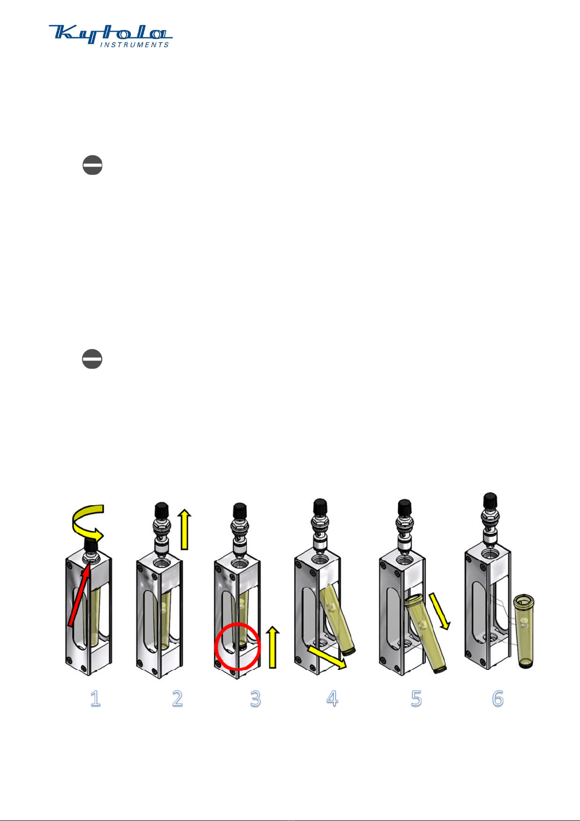
NOTE: Some floats need to be lifted upwards in the flow tube before turning the flow
tube.
CAUTION: Be careful not to damage the sealing surfaces in the lower end block.
Reassembly
To reassemble the flow meter, follow these instructions:
1 Check the cleanliness of the O-rings and sealing surfaces.
2 Replace O-rings if needed, see Chapter Change of O-rings.
3 Reassemble the flow meter parts in reverse order.
CAUTION: Check that the float is installed in the right way.
4 Place the flow tube back in its place.
5 Place the float and the guide rod attached to the valve into the flow tube.
Screw the dummy valve (model VD) or the valve (model VE) into its place.
Do this slowly not to damage the O-rings or to force them out of their
sealing grooves.
CAUTION: Do not overtighten the flow meter parts. Proper O-rings in the flow
meter do not require large tightening torque. If a leak develops, rather than tighten
the components more, replace the O-ring.
NOTE: In oil flow applications, some oil may remain in a
small pocket on the upper end of the flow tube. When
the oil warms up after start-up, it may appear as if the
meter is leaking. To avoid this, clean off the remaining
oil. For example, blow into the pocket and wipe the oil.
CAUTION: Beware not to get oil splash in your eyes.
Change of O-rings
Broken or worn-out O-rings must be removed carefully to avoid damage to the
sealing surfaces. Best results are obtained by using only fingers or soft-headed tools.
CAUTION: Do not use metallic tools.
1 Check the cleanliness of the O-rings and sealing surfaces.
2 Before installation, lightly lubricate new O-rings with silicone based
lubricant.
3 Do not damage the O-ring when moving it over threads. To protect the O-
ring, place a piece of smooth pipe over the threads or use a piece of tape or
other buffer elements.
4 Do not leave the O-ring twisted.
5 Use only factory authorized O-rings.

Contact information
Headquarters, Finland
Sales office, Sweden
Sales office, Germany
Kytola Oy
Kytola Instrument AB
Kytola Mess
-
und Regeltechnik GmbH
P.O.Box 5
Svalgången 1
Frankfurter Landstrasse 52
FI
-
40951 Muurame
S
-
72481 Västerås
D
-
63452 Hanau
Finland
Sweden
Germany
Tel. +358
20
7
79
0
690
Tel. +46 21 304 340
Tel. +49 6181 983
575
Fax +358 14
631
419
Fax +46 21 304 344
Fax +49 6181 983
578
E
-
mail info@kytola.com
E
-
mail info@kytola.se
E
-
mail info@kytola.de
www.kytola.com
www.kytola.se
www.kytola.de
Sales office, US
Sales office, Canada
Kytola Instruments Inc
Kytola Instruments Ltd
320 Maxwell Road
6600
Trans Canada Highway
Suite 600A
Suite 750
Alpharetta, GA 30009
Pointe Claire
Quebec H9R 4S2
USA
Canada
Tel. +1 678 701 3569
Tel. +1 514 630 7887
Fax +1 514 448 5151
Fax +1 514 448 5151
E
-
mail [email protected]om
E
-
mail [email protected]om
www.kytola.ca
www.kytola.ca
This manual suits for next models
1
Table of contents