TESA TESA-hite plus M 400 User manual

TESA-hite plus M 400 / 700
1
Instruction manual
TESA-hite plus M 400 /
700

TESA-hite plus M 400 / 700
2

TESA-hite plus M 400 / 700
3
LIST OF CONTENTS PAGE
1 Main features 4
2 Installation 5
2.1 Unpacking and setting up 5
2.2 Starting the instrument 6
3 Description of the components 7
3.1 Instrument base 7
3.2 Air-cushion base 7
3.3 Vertical column, measuring head and movement of the head 7
3.4 Rotary power control 7
3.5 Power supply 10
3.6 Measuring system 10
3.7 Automatic measuring value correction 10
4 Measuring 10
4.1 Basic principles 10
4.2 Control panel 12
4.2.1 Keyboard 13
4.2.2 Display 15
4.3 Starting up 18
4.4 Probing procedure at the contact point 21
4.5 Establishing the probe constant for length measurements
with inversion of the probing direction 23
4.6 Programming retraction travel 29
4.7 Capturing a reference value 30
4.8 PRESET mode 34
4.9 Measuring features with flat or cylindrical surfaces 35
4.10 Measuring centre distances of threads 36
5 PAUSE and access to the configuration menu 37
5.1 Configuration menu 38
5.2 Measuring using the reference C 44
6 Measuring functions 46
6.1 Measuring grooves 46
6.2 Measuring bores 47
6.3 Measuring shafts 50
6.4 Calculating median 53
6.5 Calculating distance 56
6.6 Measuring a diameter or a width 59
7 Additional measuring functions 60
7.1 Capturing parallelism errors 61
7.2 Measuring angles 68
7.3 Measuring perpendicularity and straightness deviations 74
7.4 2D measurement 86
7.5 Performing 2D analyses 97
8 Saving, executing a part programme and managing files 116
8.1 Creating a part programme 117
8.2 Executing a part programme 120
8.3 Managing files menu 136
9 Description of the RS 232 interface 151
10 Printing formats 152
11 Exporting data files to PC 158
12 Maintenance 161
13 Delivery programme 162
14 Technical data 166
15 Warranty 167
16 Declaration of conformity 167

TESA-hite plus M 400 / 700
4
1 MAIN FEATURES
Fig. 1
Cap cover 1
Housing 2
Mounting pin 3
Probe fixing arm 4
Probe 5
Guiding and
support faces 6
3-points cast-iron
base 7
Switch for electric
pump 9
Rotary power control 8
Control panel 10
Handle 11

TESA-hite plus M 400 / 700
5
1 MAIN FEATURES
The new TESA-Hite plus M are different from the other height gauges in that they have
exceptional performances and can be used intuitively with ease.
The unique and revolutionary rotary power control combines the speed of a manually
operated height gauge with the precision and easy handling of a motorised one.
These height gauges are specially designed for measuring lengths in the form of internal,
external, step, height or depth dimensions as well as distances. Their concept also
permits, for instance, deviations from straightness and perpendicularity to be measured.
Every TESA-Hite plus M is mechanically adjusted at our premises based on a TESA’s
patented system, thus allowing random errors in perpendicularity to be quickly and easily
detected using a dial test indicator.
Value processing is ensured via the integrated control panel (IP65), with or without built-in
printer; thus enabling single or two coordinate measurements to be carried out as well as
bore position to be determined, both in polar and rectangular coordinates. Furthermore,
the TESA-Hite plus M can measure straightness and perpendicularity along with angles.
The cast-iron base features three resting points precisely ground to ensure high stability.
Once integrated, the electric pump generates the air-cushion so that your height gauge
can easily be moved across the surface plate.
The rigid column under the housing includes the guiding part that is rigorously straight and
perpendicular to the base. The patented opto-electronic system measures any head
displacement. Value acquisition is very simple and reliable. Rotating the power control or
activating the appropriate function key causes the insert to move to the point to be probed
automatically. The measured value is then captured after a wait for stabilisation. A
constant measuring force is ensured by the mechanical friction release mechanism, which
has been specially developed for this purpose. An acoustic signal confirms the capture of
the measured values, which are displayed at once and further transferred via the RS
output provided they are judged to be correct.
Round-shaped cylindrical surfaces (e.g. bores or shafts) can equally be inspected easily
and reliably through automatic detection of the culmination point.
The computer-aided value correction enhances the accuracy of every TESA-Hite plus M
even further. The correction values stored in the electronics compensate for the bias
errors when measuring lengths.
The rechargeable battery assures the autonomy of the instrument. Continuous mains
independent operation is ensured with no cumbersome cables or power cord to hinder the
operator.
2 INSTALLATION
2.1 Unpacking and setting up
The TESA-Hite plus M 400 / 700 is delivered ex factory, packed to protect it from impact
and corrosion. Please use the original packing materials for any subsequent transport.
IMPORTANT:
Your instrument is supplied with a 6V rechargeable battery already inserted. For
recharging the battery, see section 12.2.
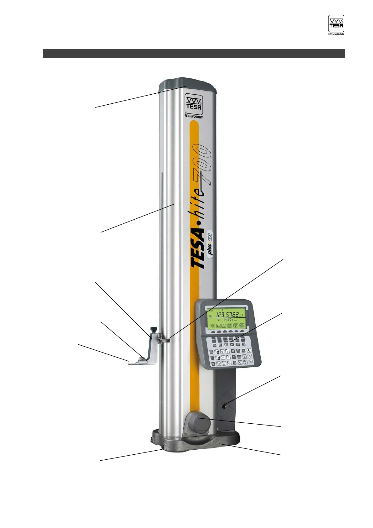
Before fitting the standard accessories, release the measuring carriage by removing the
transport support. Securely fit the probe 5 to the probe-fixing arm 4 itself fitted to the
mounting pin 3. Ensure that the two knurled screws on the probe-fixing arm are well
tightened.
However, we recommend you firstly read this instruction manual.

TESA-hite plus M 400 / 700
6
2.2 Starting the instrument
Activate the electric pump using the relevant switch (11) to generate the air-cushion for
easy displacement of the TESA-Hite plus M 400 / 700 on the surface plate.
Next, start the height gauge by pressing key for more than one second.
Starting up
This causes the measuring head to move past the reference mark and position itself at the
point where the master piece is located. Head displacement can be accelerated by using
either the handle or the rotary power control. (For more details, see chapter 4.3)
Enclencher l'instrument
Déplacement automatique de la touche, passage au travers du
repère pour initialisation. La touche se positionnera à la
hauteur du centre de la jauge de calibration
ON
OFF
Prise de la
constante
St2: Saisir le
point de référence
Mesurer
St1: Saisir le
point de référence
Mesurer
non
Annule la
référence
A ou B
Annule les
références
A et B
Annule la
référence
A ou B
Annule les
références
A et B
Switch the instrument ON
Probe insert moves automatically, travels past the reference mark
of the precision glass scale for initialisation, then places itself into
position at the master piece.
Probe constant
capture
St2 : Probe
datum point
St1 : Probe
datum point
Cancel both
references
A and B
Cancel
reference
A or B
Cancel
reference
A or B
Cancel both
references
A and B
Measure
Measure

TESA-hite plus M 400 / 700
7
3 DESCRIPTION OF THE COMPONENTS
3.1 Instrument base
The base is chemically nickel-plated in order to make it very resistant to corrosion. Its
lower face,
which has been machined to ensure that it is rigorously flat, incorporates three finely-
machined support lugs that guarantee the stability of the TESA-Hite plus M 400 / 700.
These lugs form a large surface so that any grooves or other similar irregularities in the
surface plate can be comfortably cleared. The lugs 6 (Fig. 1) are designed especially for
supporting the TESA-Hite plus M 400 / 700 against a parallel rule or for guiding it along
such a rule, for example.
3.2 Air-cushion base
The air-cushion base, which is generated by the
pneumatic system linked to the electric pump integrated
into the instrument, permits the height gauge to be
moved safely and easily. Once activated, manually with
the button 9 (Fig. 1), the pump creates an air-cushion
only a few µm thick between the height gauge base and
the surface plate so that TESA-Hite plus M 400 / 700
can be displaced effortless and quite wear-free. The
thickness of the air cushion can be set according to the
surface quality of the granite plate. This is done by
turning screw (Fig. 2), which acts on the valve located
into the pneumatic system. Experience has shown that
the air cushion should not be thicker than necessary.
Once enabled, it has to support the weight of the height
gauge while contacting the surface plate lightly. Fig. 2
3.3 Vertical column, measuring head and movement of the head
The rigid vertical column is perpendicular to the base, to which it is permanently fixed. A
measuring head slides on the guide and the movement of the head is recorded by an
opto-electronic measuring system (TESA patent). A counterweight is mounted on the steel
tape supporting the measuring head. This enables it to stand still in any position with use
of the accessories that came with your TESA-Hite plus M 400 / 700.
Head displacement is electro-motorised. This includes a servomotor drive which allows
you to set
the speed at which you want the head to be shifted, conveniently. The specially designed
friction mechanism ensures a constant measuring force during the measurement
operations.
3.4 Rotary power control
A rotary power control, with a revolutionary design is
located close to the base. It serves for shifting the
instrument on the air-bearing, for commanding fast
motion of the probe insert as well as for triggering all
main measuring functions.
Since the rotary power control is used intuitively,
the instrument moves quickly and precisely across
the surface plate. It needs just be rotated clockwise

TESA-hite plus M 400 / 700
8
or counterclockwise for approaching the measuring
point whether quickly or slowly, probing up and down
or performing bore measurement.
Operating functions using the rotary power control
Usually, these functions are identical to those of
the keypad.
Ways to move the probe insert
- Turn the rotary power control clockwise
to move it up (Fig. 1).
- Turn the rotary power control
counterclockwise to move down (Fig. 2).
Fig. 1 Fig. 2
Fast displacement Positioning
probe insert
A continuous rotation
Causes the probe insert to
move even faster
(according to the angle the
power control is rotated)
and to decelerate or stop
when approaching the
zero point (■) or releasing
the rotary power control.
Probing up Probing down

TESA-hite plus M 400 / 700
9
Short rotation (<0,7 s) in the probing direction.
Bore measurement
A second short rotation of the power control in the
same direction permits bore measurement with
detection of the culmination point.
- Turn the power control clockwise to start
probing the upper point.
- Turn the rotary power control
counterclockwise, to start probing the
lower point first.
Stop
A second or third short rotation in reverse
direction causes the probe insert to stop.
The selected measuring function is then quit.
Fast displacement
When measuring bores or grooves, this function
can be enabled to shift the probe faster from the
upper to the lower point and the other way round.

TESA-hite plus M 400 / 700
10
3.5 Power supply
The TESA-Hite plus M 400 / 700 is powered by a 6V rechargeable battery (N° 00760157).
This is recharged using the mains adapter N° 04761054 and the cable EU N° 04761055
or US N° 04761056
(see chapter 12.2 – Charging the battery).
3.6 Measuring system
The TESA-Hite plus M 400 / 700 incorporates an opto-electronic measuring system
(TESA’s patent), which catches the measured quantity (also known as measurand)
digitally. The glass scale with both incremental graduations and reference mark serve as
material measure. According to the principle of the reflected light, each graduation is
scanned by the photocells inside the optical sensor, with no mechanical contact. As next
step, the measurement signal is transmitted to the control panel, which operates an
analogue/digital conversion.
The probing procedure is either started by activating a measuring function or rotating the
power control. As soon as the measuring insert enters into contact with the point to be
probed, the friction clutch ensures a constant measuring force. After a wait for
stabilisation, the measured value is processed through the control panel.
3.7 Automatic measuring value correction
It is agreed that a perfectly accurate measuring instrument is impossible to produce.
Therefore, the value indicated by any instrument comprises a deviation from the true
value; this deviation is composed of the bias errors and the random errors. Random errors
cannot be predicted since they are the result of influences that cannot be controlled, e.g.
the value dispersion. Bias errors, on the other hand, as for example the deviations of the
scale divisions on the material measure or the form and positional errors of the measuring
head guides can be corrected once they have been measured. To correct length
measurements, after the TESA-Hite plus M 400 / 700 has been completely assembled;
the actual errors are determined step-by-step by means of a system of stepped gauge
blocks.
The correction values thus calculated will subsequently be memorised in the electronic
module of the instrument. Thus, every measurement read off by the TESA-Hite plus M
400 / 700 will be automatically corrected before being displayed.
4 MEASURING
4.1 Basic principles
The way TESA-Hite plus M 400 / 700 will execute a value acquisition often depends on
the measuring application, which is mainly based on the following:
- Measuring without inversion of the probe direction (St1).
- Measuring with inversion of the probe direction (St2).
- Detection form, parallelism or run-out errors.
- Measuring perpendicularity errors using TESATAST.
- Measuring perpendicularity and straightness with aid of a digital instrument.
- Measuring angles.

TESA-hite plus M 400 / 700
11
- Measuring in two coordinate directions.
Measuring without inversion of the probing direction
Making no allowance for the probe constant
Measuring with inversion of the probing direction
Making allowance for the probe constant
- with no storage of the culmination point - with storage of the
culmination point
Capturing form and position errors
Parallelism Radial
error run-out error
« max »

TESA-hite plus M 400 / 700
12
« min »
« max »-« min »
Measuring in two coordinate directions
4.2 Control panel

TESA-hite plus M 400 / 700
13
4.2.1 Keyboard
-
Function keys
Press tp switch height gauge on or off.
Keep pressing this key ( > 0.6 sec) to get confirmation.
Reset the measuring counter to 0.
Initialisation of the programme to be saved « Learn ».
Cancel both references A and B and return to menu St1/2 to take a
new reference A and/or B along with probe constant if you wish to.
This key also permits to return to St1/2 from any menu. Reset also
the measuring counter to 0 and initialise of the programme to be
saved « Learn ».
Press shortly: to probe up
Keep pressing this key: to move probe up quickly. Probe will stop
moving as soon as you release it.
Probing up with detection of the highest culmination point.
Probing up with detection of the lowest culmination point.
Press shortly: to probe down
Keep pressing this key: to move probe down
quickly. Probe will stop
moving as soon as you release it.
Probing down with detection of the lowest culmination point.

TESA-hite plus M 400 / 700
14
Probing down with detection of the highest culmination point.
Measure the centre and width of a grove.
Measure the centre and diameter of a bore.
Measure the centre and diameter of a shaft.
Cancel last function or probing operation.
Enable the difference between the last two probe contacts or
numbered values selected in the memory to be calculated and
further displayed
ENTER key to validate your operation
Press shortly (< 0,6 s) to transfer the value from the main display to
a peripheral device.
Keep pressing this key (> 0,6 s) to transfer full table contents to a
peripheral.
Enable the mean value from the last two probe contacts or
numbered values selected in the memory to be calculated and
further displayed
Access to additional measuring functions
Idle mode and access to the configuration menu.

TESA-hite plus M 400 / 700
15
Create a « Learn » programme.
Executing a programme.
Managing programme and data files.
Allows the cursor to move up by one position or one field.
In measuring mode: Entry in the measurement memory and display
the first 4 values with scrolling of the other one by one.
Allows the cursor to move to the left by one position or one field.
In measuring mode: Entry in the measurement memory and display
the first 4 values with scrolling of the other four by four. Keep
pressing this key
(> 0,6 s) to introduce the 0 if there is a conflict with the cursor
displacement.
Allows the cursor to move down by one position or one field.
In measuring mode: Entry in the measurement memory and display
the last 4 values with scrolling of the other one by one. Keep
pressing this key
(> 0,6 s) to introduce the . if there is a conflict with the cursor
displacement.
Allows the cursor to move to the right by one position or one field.
In measuring mode: Entry in the measurement memory and display
the last 4 values with scrolling of the other four by four. Keep
pressing this key
(> 0,6 s) to introduce the - if there is a conflict with the cursor
displacement.
4.2.2 Display
The LCD display has to distinctive parts :.
Upper part :
- Main display is split into segments, providing high visibility necessery to inspect
parts in the industrial envirennement.
Lower part:
- Auxiliary display is a full dot display, allowing a wide number of symbols to be
created to make the height gauge easy tu use and to learn.
Displayed values:
- Main display : measured values plus symbols for the functions (7 segments/sign)
- Auxiliary display : perpendicularity and straightness measurement plus symbols
Dimensions:
Display size 128 x 63 mm
Main display 12,7 x 6,4 mm (7 decade display plus minus sign)
Auxiliary display 6,3 x 4,2 or 3,8 x 2,9 mm (7 decade display plus minus sign)
Active reference
Numbered value Symbol of the measured part
feature

TESA-hite plus M 400 / 700
16
Symbol
empty battery
Built-in
printer (ON) Measured value
Date output
(ON)
Auxiliary measured value
Symbols of the function keys

TESA-hite plus M 400 / 700
17
Main display
Displayed data
related to a bore
(example)
-F1 Prompt for new probe constant.
-F2 Prompt for new capture of the relevant reference value
(the counter of the measure is not reset to zero).
-F3
1) Displaying of the difference value obtained from the last two displayed
values.
2) Automatic displaying of the difference value obtained from the last two
measured values.
3) Quit « Automatic displaying of the difference value obtained from
the last two measured values ».
-F4
1) Temporary displaying of the difference value resulting from two probe
contacts made on a bore, a shaft or a groove on the main display.
2) Continuous displaying of the difference value resulting from two probe
contacts made on a bore, a shaft or a groove on the main display.
3) Quit « Continuous displaying of the difference value resulting from two
probe contacts made on a bore, a shaft or a groove on the main display
»
-F5
1) Prompt for base reference B.
2) Prompt for base reference A.

TESA-hite plus M 400 / 700
18
Display format in mode measurement
Auxiliary display large format
Display the last
measured value.
Auxiliary display small format
Display the last 4
measured values.
4.3 Starting up

TESA-hite plus M 400 / 700
19
Switching On
Press this key
(> 0,6 s)
to initialise your
control panel and
load correction
values stored in
the EEPROM.
Firmware V X.XX
shows the
software version.
Searching for the reference mark
Move up over a
distance of approx.
100 mm, or down
if you can’t get any
value.
V-shaped sign
indicates the
direction to which
carriage moves.
Accessing test menu
Once you’ve travelled past the reference mark, probe insert
will automatically position itself up to the centre of the
master piece
Start probe
constant
acquisition using
or
rotating the power
control by 1 click
for probing internal
part
or pressing
for
probing external

TESA-hite plus M 400 / 700
20
Accessing the test menu
> Burn in, Moving up and down automatically
> Test the internal printer, print all characters
> Test the display, show all characters
> Test the keyboard
> Cancelling all data files
> Exit test menu
Press a keyboard
key and the
corresponding
character will be
displayed
between the 2
arrows.
Press the
function’s key F4
to return to the
previous menu.
This manual suits for next models
1
Table of contents
Other TESA Measuring Instrument manuals

TESA
TESA Micro-Hite Plus M User manual

TESA
TESA TESA-hite Magna 400 User manual

TESA
TESA TESATRONIC TT20 User manual

TESA
TESA Micro-Hite 10 Setup guide

TESA
TESA TESA-hite 400 User manual

TESA
TESA MICRO-HITE User manual

TESA
TESA HEXAGON RUGOSURF 90G User manual

TESA
TESA CLINOBEVEL 3 User manual

TESA
TESA HEXAGON DIALTRONIC EASY User manual

TESA
TESA HEXAGON TWIN-CAL User manual