L-ACOUSTICS LA 24 MANUAL Version 2.2 17/11/08 7
Once the AC connector i connected to a uitable AC upply, the amplifier can be tarted by
pre ing the AC power witch. When you power up the amplifier it take a couple of econd
to check it circuit (thi i known a the " oft tart" or " low tart" equence), the fan then
blow at high peed before going into "idle" and the 2 bottom green LED’ come on to how
the output circuit are receiving the correct rail voltage.
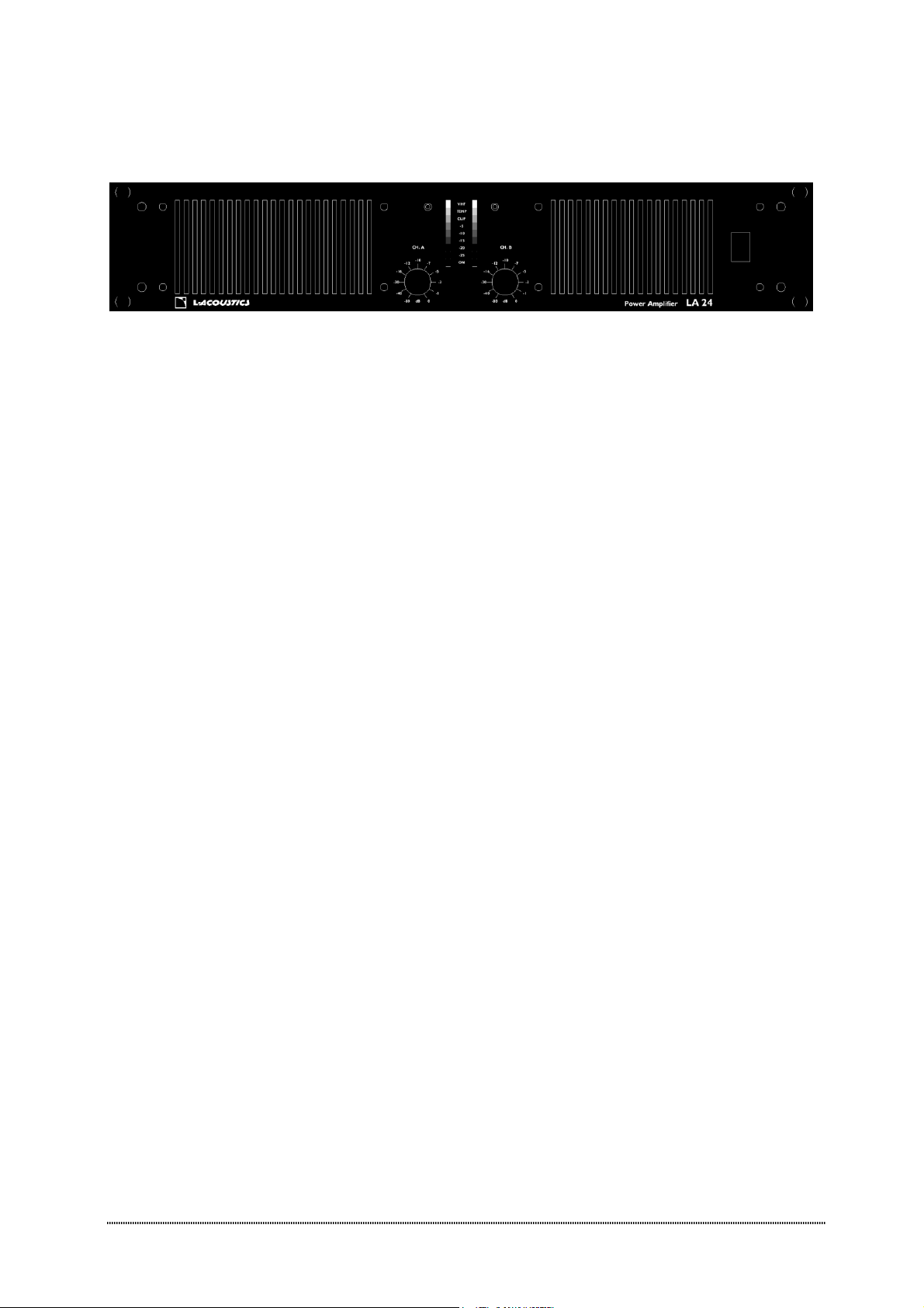
Grounding
There i no ground lift witch or terminal on thi amplifier. The ignal ground i alway floating
via a re i tor to cha i and the grounding y tem i automatic. If a potential above 0.6 V
pre ent it elf between ignal ground and cha i ground, a hort circuit i introduced between
the two, thereby enabling electrical protection. If a unit in the y tem i faulty, it main fu e
will blow due to thi automatic ground y tem.
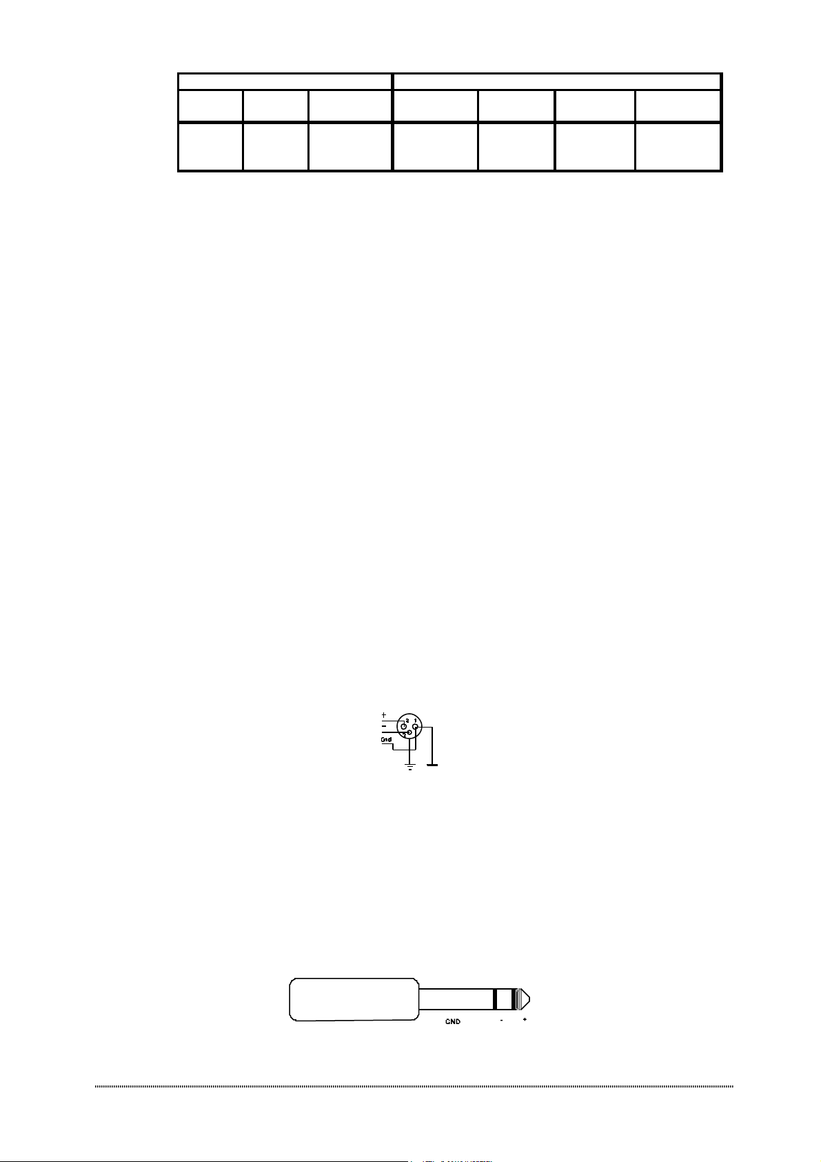
If you want to tie the ignal ground to cha i , connect the XLR-connector’ hell lug to pin 1.
In the intere t of afety never di connect the earth pin on the AC cord.
For all unit that are EMC approved for radio interference there i an AC main filter. Thi
filter need the cha i ground for reference, otherwi e a current loop i formed via the ignal
ground.
U e the balanced input to avoid hum and interference.
ower consumption
There are three way to determine the power/current con umption of the amplifier:
Fir t, the peak current draw at full output power. Under thi condition the power will
trip the wall breaker within 30 econd and the amplifier will operate for le than 2 minute
before thermally limiting. During thi time, the temperature of the power upply will be
tabilized at a temperature that will have no effect on the in ulation rating of the AC line cord.
Secondly, the maximum expected average current under wor t ca e program material i
1/3 of full power according to the FTC tandard. At thi level the mu ic will be in a tate of
con tant clip and thi i therefore the highe t power level one can obtain without completely
obliterating the program.
Finally, the "normal operating power", a mea ured according to afety tandard IEC 65
and u ed by a majority of afety agencie . The normal operating power i mea ured u ing pink
noi e, with an average output power equal to 1/8 of full power. One eighth of the total
power i a loud a you can play mu ic while making ome attempt to avoid obviou clipping.
It al o corre pond to a headroom of 9 dB, which i very low for audio program.
For 2 ohm operation, the AFS-protection of the amplifier circuit will not permit long term
current draw and the component temperature ri e will tabilize well below the rating.