L-Acoustics K3i User manual

K3i
owner's manual (EN)

Document reference: K3i owner's manual (EN) version 1.0
Distribution date: April 22, 2021
© 2021 L-Acoustics. All rights reserved.
No part of this publication may be reproduced or transmitted in any form or by any means without the
express written consent of the publisher.

Contents
Safety................................................................................................................................................................ 5
Instructions................................................................................................................................................5
Introduction........................................................................................................................................................ 7
K3i long throw line source for install.......................................................................................................... 7
How to use this manual............................................................................................................................ 7
System components.............................................................................................................................................8
System component illustrations....................................................................................................................9
Electro-acoustical description..............................................................................................................................11
Adjustable ns........................................................................................................................................11
Directivity............................................................................................................................................... 14
Preset description....................................................................................................................................15
Connectors............................................................................................................................................. 16
Rigging system description.................................................................................................................................17
K3i........................................................................................................................................................ 17
Rigging elements.....................................................................................................................................19
K3i-BUMP..................................................................................................................................... 19
K3i-BAR...................................................................................................................................... 21
K3i-RIGBAR...................................................................................................................................22
KARAIIi-DOWNK3i...................................................................................................................... 24
K3i-TILTBRACKET........................................................................................................................... 26
K3i-CEILINGBRACKET.................................................................................................................... 28
K3i-SCREEN........................................................................................................................................... 29
Mechanical safety.............................................................................................................................................30
Loudspeaker congurations................................................................................................................................ 32
Line source.............................................................................................................................................32
Line source with low-frequency element..................................................................................................... 33
Additional downll element......................................................................................................................35
Rigging procedures...........................................................................................................................................37
General principles...................................................................................................................................37
Tools...................................................................................................................................................... 39
Flying.....................................................................................................................................................40
Flying a K3i array with K3i-BUMP.................................................................................................. 40
Adding a pullback with K3i-RIGBAR............................................................................................... 46
Rigging a Kara IIi downll array under a K3i array with KARAIIi-DOWNK3i.......................................49
3

Ceiling-mounting a K3i array with K3i-CEILINGBRACKET............................................................................53
Stacking a K3i array on K3i-TILTBRACKET.................................................................................................58
Securing a screen................................................................................................................................... 62
Connection to LA amplied controllers................................................................................................................63
Cabling..................................................................................................................................................64
Specications................................................................................................................................................... 68
APPENDIX A: Recommendation for speaker cables.............................................................................................. 83
APPENDIX B: Specications for custom rigging system......................................................................................... 84
4

Safety
Safety
Instructions
Inspect the system before any deployment.
Perform safety related checks and inspections before any deployment.
Perform preventive maintenance at least once a year.
Refer to the preventive maintenance section for a list of actions and their periodicity.
Insufcient upkeep of the product can void the warranty.
If any safety issue is detected during inspection, do not use the product before performing
corrective maintenance.
Check for issues. A rigging system part or fastener is missing or loose. A rigging system part exhibits: bends,
breaks, broken parts, corrosion, cracks, cracks in welded joints, deformation, denting, wear, holes. A safety cue
or label is missing. A loose part is not adequately secured.
Never incorporate equipment or accessories not approved by L-Acoustics.
Read all the related PRODUCT INFORMATION documents shipped with the products before
exploiting the system.
Do not store the product on an unstable cart, stand, tripod, bracket, or table.
Beware of sound levels.
Do not stay within close proximity of loudspeakers in operation.
Loudspeaker systems are capable of producing very high sound pressure levels (SPL) which can instantaneously
lead to permanent hearing damage to performers, production crew and audience members. Hearing damage
can also occur at moderate level with prolonged exposure to sound.
Check the applicable laws and regulations relating to maximum sound levels and exposure times.
Work with qualied personnel for rigging the system
Installation should only be carried out by qualied personnel that are familiar with the rigging techniques and
safety recommendations outlined in this manual.
Ensure personnel health and safety
During installation and set-up personnel must wear protective headgear and footwear at all times. Under no
circumstances is personnel allowed to climb on a loudspeaker assembly.
Respect the Working Load Limit (WLL) of third party equipment.
L-Acoustics is not responsible for any rigging equipment and accessories provided by third party manufacturers.
Verify that the Working Load Limit (WLL) of the suspension points, chain hoists and all additional hardware
rigging accessories is respected.
Respect the maximum congurations and the recommended safety precautions.
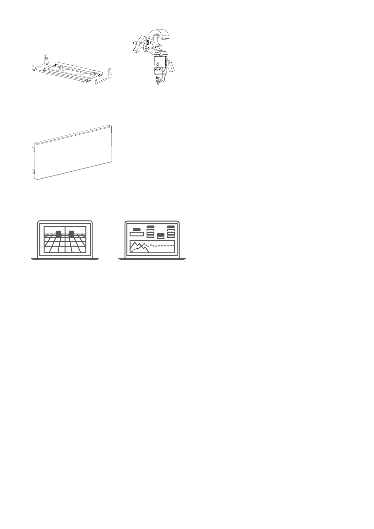
For safety issue, respect the maximum congurations outlined in this manual. To check the conformity of
any conguration in regards with the safety precautions recommended by L-Acoustics, model the system in
Soundvision and refer to the warnings in Mechanical Data section.
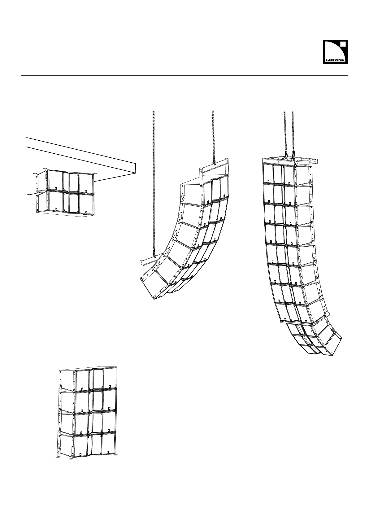
Be cautious when ying a loudspeaker conguration.
Before installing/raising the product, check each individual element to make sure that it is securely fastened to the
adjacent element. Always verify that no one is standing underneath the product when it is being installed/raised.
Never leave the product unattended during the installation process.
As a general rule, L-Acoustics recommends the use of secondary safety at all times.
Be cautious when ground-stacking a loudspeaker array.
Do not stack the loudspeaker array on unstable ground or surface. If the array is stacked on a structure, platform,
or stage, always check that the latter can support the total weight of the array.
As a general rule, L-Acoustics recommends the use of safety straps at all times.
K3i owner's manual (EN) version 1.0 5

Safety
Risk of falling objects
Verify that no unattached items remain on the product or assembly.
Risk of tipping
Remove all rigging accessories before transporting a product or an assembly.
Take into account the wind effects on dynamic load.
When a loudspeaker assembly is deployed in an open air environment, wind can produce dynamic stress to the
rigging components and suspension points.
If the wind force exceeds 6 bft (Beaufort scale), lower down and/or secure the product or the assembly.
Intended use
This system is intended for use by trained personnel for professional applications.
As part of a continuous evolution of techniques and standards, L-Acoustics reserves the right
to change the specications of its products and the content of its documents without prior
notice.
Check www.l-acoustics.com on a regular basis to download the latest document and software updates.
Long term exposure to extreme conditions may damage the product.
For more information, refer to the Products weather protection document, available on the website.
Read the maintenance section of this document before servicing the product.
Contact L-Acoustics for advanced maintenance.
Any unauthorized maintenance operation will void the product warranty.
Before sending a product to L-Acoustics for maintenance, save all user presets to les using LA Network Manager.
This marking indicates that this product should not be disposed of with other household waste throughout the
EU. To prevent possible harm to the environment or human health from uncontrolled waste disposal, recycle it
responsibly to promote the sustainable reuse of material resources. To return your used device, please use the
return and collection systems or contact the retailer where the product was purchased. They can take this product
for environmentally safe recycling.
6 K3i owner's manual (EN) version 1.0

Introduction
Introduction
K3i long throw line source for install
K3i is the installation version of K3, designed for long-throw installation applications. K3i shares identical sonic
performance with its touring counterpart but features a sleeker design and streamlined mounting hardware tting
integration requirements.
Housing the internationally recognized K2 performance into a compact enclosure, K3i is ideal for medium to large-scale
venues that require premium-tour sound and limited footprint, such as large concert halls, clubs, congress centers and
sport venues.
Inter-element angles and Panex™ for user-adjustable horizontal directivity enable integrators, consultants and sound
designers to precisely tailor the array coverage to any audience geometry.
Requiring only two channels of amplication, K3i is a high value solution that provides large-format concert sound in
compact and lightweight construction to facilitate most integration scenarios. K3i is highly weather-resistant as standard
and can be color-matched to melt into any venue decor, indoor or outdoor.
How to use this manual
The K3i owner's manual is intended for all actors involved in the system design, implementation, preventive and
corrective maintenance of the K3i system. It must be used as follows:
1. Read the technical description for an overview of all system elements, their features, and their compatibilities.
•Electro-acoustical description (p.11)
•Rigging system description (p.17)
2. Prepare the system conguration. Consider the mechanical limits and the available acoustical congurations.
•Mechanical safety (p.30)
•Loudspeaker congurations (p.32)
3. Before rigging the system, perform mandatory inspections and functional checks.
4. To deploy the system, follow the step-by-step rigging instructions and refer to the cabling schemes.
•Rigging procedures (p.37)
•Connection to LA amplied controllers (p.63)
As part of a continuous evolution of techniques and standards, L-Acoustics reserves the right to
change the specications of its products and the content of its document without prior notice. Please
check www.l-acoustics.com on a regular basis to download the latest document and software updates.
Contact information
For information on advanced corrective maintenance:
• contact your Certied Provider or your L-Acoustics representative
• for Certied Providers, contact the L-Acoustics customer service: customer.ser[email protected]
K3i owner's manual (EN) version 1.0 7

System components
Symbols
The following symbols are used in this document:
This symbol indicates a potential risk of harm to an individual or damage to the product.
It can also notify the user about instructions that must be strictly followed to ensure safe installation or operation of
the product.
This symbol noties the user about instructions that must be strictly followed to ensure proper installation or
operation of the product.
This symbol noties the user about complementary information or optional instructions.
System components
Loudspeaker enclosures
K3i 2-way active WST® enclosure: 2 x 12" LF + 4" HF diaphragm (installation version)
Kara IIi 2-way active WST® enclosure: 2 × 8" LF + 3" HF diaphragm (installation version)
KS28 Flyable subwoofer 2 x 18''
KS21i High power compact subwoofer: 1 x 21" (installation version)
Powering and driving system
LA4X / LA8 / LA12X Amplied controller with DSP, preset library and networking capabilities
Refer to the LA4X / LA8 / LA12X owner's manual for operating instructions.
Cables
speaker cable 4 x 2.5mm2 cable
Speaker cable used to connect 2-way active enclosures in parallel. Adapt the cable length to
the installation.
speaker cable 2.5mm2 cable
Speaker cable used to connect enclosures in parallel. Adapt the cable length to the installation.
custom 4-point
speakON cable
4-point speakON cable (2.5mm2 gauge) to bare wire cable
This cable needs to be custom made.
Information about the connection of the enclosures to the LA amplied controllers is given in
this document.
Refer to the LA4X / LA8 / LA12X owner's manual for detailed instructions about the whole cabling scheme,
including modulation cables and network.
Rigging elements
K3i-TILTBRACKET Fastening bracket with angles for K3i
K3i-CEILINGBRACKET Ceiling fastening bracket with angles for K3i
K3i-LINK Rigging plate for K3i
K3i-ENDLINK End rigging plate for K3i
K3i-BUMP Flying frame for K3i
K3i-BAR Extension bar for K3i-BUMP
8 K3i owner's manual (EN) version 1.0

System components
K3i-RIGBAR Rigging bar and pullback for K3i
KARAIIi-DOWNK3i Interface for ying Kara IIi below K3i
CLAMP250 Clamp certied for 250 kg
Screens
K3i-SCREEN Acoustically transparent front screen for K3i
Software applications
Soundvision 3D acoustical and mechanical modeling software
LA Network Manager Software for remote control and monitoring of amplied controllers
Refer to the Soundvision help.
Refer to the LA Network Manager help.
System component illustrations
Cables
1+
1-
2+
2-
1+
1-
2+
2-
+
-
+
-
1+
1-
2+
2-
4 × 2.5 mm cable 2.5 mm cable custom 4-point speakON cable
Rigging plates
x2
x2 x2 x2
K3i-TILTBRACKET K3i-
CEILINGBRACKET
K3i-LINK K3i-ENDLINK
Rigging accessories
K3i-BUMP K3i-BAR K3i-RIGBAR
K3i owner's manual (EN) version 1.0 9

System components
KARAIIi-DOWNK3i CLAMP250
Screens
K3i-SCREEN
Software applications
Soundvision LA Network Manager
10 K3i owner's manual (EN) version 1.0

Electro-acoustical description
Adjustable ns
The K3i enclosure features an adjustable horizontal directivity system. Using the adjustable ns, horizontal directivity can
be adjusted with four different settings: 70° / 110° symmetric or 90° asymmetric. A specic K3i preset must be used for
each directivity setting.
Within a line source, different directivity settings can be combined to improve the coverage of the audience geometry.
70° setting (preset [K3 70])
Set the ns in the 70° position to provide the system with a 2 dB on-axis gain (> 1 kHz), compared to the 110° setting.
K3i owner's manual (EN) version 1.0 11

Electro-acoustical description
90° settings (preset [K3 90])
12 K3i owner's manual (EN) version 1.0

Electro-acoustical description
110° setting (preset [K3 110])
Mixed settings
K3i owner's manual (EN) version 1.0 13

Electro-acoustical description
Directivity
Horizontal
100 1 000 10 000
Frequency (Hz)
-180
-160
-140
-120
-100
-80
-60
-40
-20
0
20
40
60
80
100
120
140
160
180
Angle (°)
Dispersion angle diagram of a K3i array with 70° ns setting, using lines of equal sound pressure at -3 dB, -6 dB, -12
dB.
100 1 000 10 000
Frequency (Hz)
-180
-160
-140
-120
-100
-80
-60
-40
-20
0
20
40
60
80
100
120
140
160
180
Angle (°)
Dispersion angle diagram of a K3i array with 90° ns setting, using lines of equal sound pressure at -3 dB, -6 dB, -12
dB.
100 1 000 10 000
Frequency (Hz)
-180
-160
-140
-120
-100
-80
-60
-40
-20
0
20
40
60
80
100
120
140
160
180
Angle (°)
Dispersion angle diagram of a K3i array with 110° ns setting, using lines of equal sound pressure at -3 dB, -6 dB, -12
dB.
14 K3i owner's manual (EN) version 1.0

Electro-acoustical description
Preset description
[K3 70] [K3 90] [K3 110] [KARAIIDOWNK3]
loudspeaker elements outputs channels routing gain delay polarity mute
LF OUT 1 LF ON
HF OUT 2 HF
IN A 0 dB 0 ms +
ON
LF OUT 3 LF ON
HF OUT 4 HF
IN A 0 dB 0 ms +
ON
[KS28_60] [KS21_60]
outputs channels routing gain delay polarity mute
OUT 1 SB IN A 0 dB 0 ms + ON
OUT 2 SB IN A 0 dB 0 ms + ON
OUT 3 SB IN A 0 dB 0 ms + ON
OUT 4 SB IN A 0 dB 0 ms + ON
[KS28_60_C] [KS28_60_Cx] [KS21_60_C] [KS21_60_Cx]
loudspeaker elements outputs channels routing gain delay polarity mute
SR OUT 1 SR ON
SB OUT 2 SB ON
SB OUT 3 SB ON
SB OUT 4 SB
IN A 0 dB 0 ms +
ON
K3i owner's manual (EN) version 1.0 15

Electro-acoustical description
Connectors
K3i
2 × 4-point terminal blocks with push-in connection
Internal pinout for L-Acoustics 2-way active enclosures
terminal block points 1 + 1 - 2 + 2 -
Transducer connectors LF + LF - HF + HF -
16 K3i owner's manual (EN) version 1.0

Rigging system description
K3i
The K3i system is the installation version of the K3 system and features a simplied rigging system to optimize visual
impact.
The enclosures are assembled together with rigging plates and rigging accessories suited for installation. Like the K3
system, the enclosures can be deployed in own or stacked arrays. Multiple rigging kits are available depending on the
desired conguration (refer to System component illustrations (p.9)).
K3i is compatible with two types of rigging plate kits:
standard rigging plates (K3i-LINK) end rigging plates (K3i-ENDLINK)
K3i-LINK can be used to add an inter-element angle of 0.25°, 1°, 2°, 3°, 4°, 5°, 7.5° or 10° between two K3i.
1°
4°
7.5°
0.25°
3°
2°
5°
10°
BA
C
K3i owner's manual (EN) version 1.0 17

Rigging system description
K3i features on each side:
Eight M8 inserts for own congurations
with a rigging frame or stacked congurations.
Two M6 inserts for securing a screen.
All inserts are tted with placeholder screws. Leave the placeholder screws in the inserts that are not used.
The three inserts at the bottom rear on each side are used depending on the rigging accessory secured under the
enclosure, and on the inter-element angle.
A
C
B
C
B
A
Risk of acoustic leaks
Do not remove the placeholder screws from the bottom rear inserts (A, B or C) that are not used.
rigging accessory inter-element angles used insert
0.25°, 3° C
2°, 5°, 10° B
K3i-LINK (connecting from an
enclosure below) / KARAIIi-
DOWNK3i 1°, 4°, 7.5° A
K3i-RIGBAR — B
K3i-TILTBRACKET 5°, 2.5°, 0°, -2.5°, -5°, -7.5°, -10°, -12.5°, -15° A
It is recommended to use the rigging report from Soundvision to prepare the enclosures.
Rigging screws
Only use the rigging screws provided by L-Acoustics.
Do not use the placeholder screws for rigging.
Always put the placeholder screws back in place to avoid leaks.
18 K3i owner's manual (EN) version 1.0

Rigging system description
Rigging elements
K3i-BUMP
K3i-BUMP is a rigging frame designed for ying K3i.
K3i-BUMP can be used as the main lifting accessory for ying arrays of K3i.
K3i owner's manual (EN) version 1.0 19

Rigging system description
K3i-BUMP is secured to the array with four M8x35 rigging screws and M8 nuts (provided). With K3i-LINK, the splay
angle with K3i can be set to 0°, 2.5°, 5°.
To calculate the site angle of the rst enclosure, subtract the splay angle from the site angle of K3i-BUMP.
2.5° splay angle
0° K3i-BUMP site angle
0-2.5 = -2.5° K3i site
angle
5° splay angle
0° K3i-BUMP site angle
0-5 = -5° K3i site angle
In Soundvision, the splay angles are labeled as follows (Elements panel):
angle in Soundvision splay angle
5° 0°
7.5° 2.5°
10° 5°
It is recommended to set a 0° splay angle (5° in Soundvision) between the rst K3i and K3i-BUMP.
By doing this, the K3i axis is parallel to K3i-BUMP.
2.5° 0°
5°
Four holes are available on the central bar of the K3i-BUMP for site angle adjustments. Four additional holes are
available to add K3i-BAR to K3i-BUMP as an extension to increase the site angle.
1 2 34
A AB B
20 K3i owner's manual (EN) version 1.0
Table of contents
Other L-Acoustics Stereo System manuals