EN
5RIGGING STRUCTURE KIBU AND MOUNTING
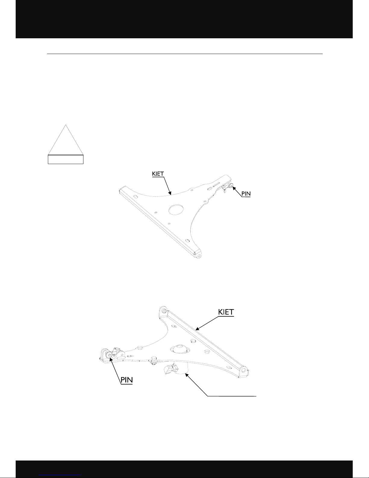
ACCESSORY KIET
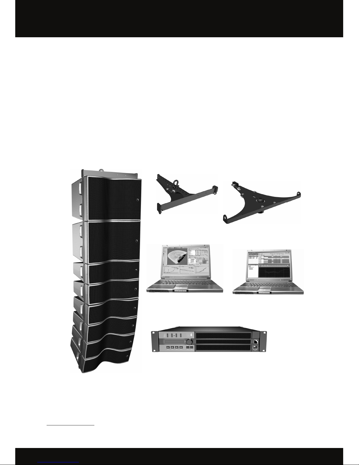
5.1 Rigging structure KIBU
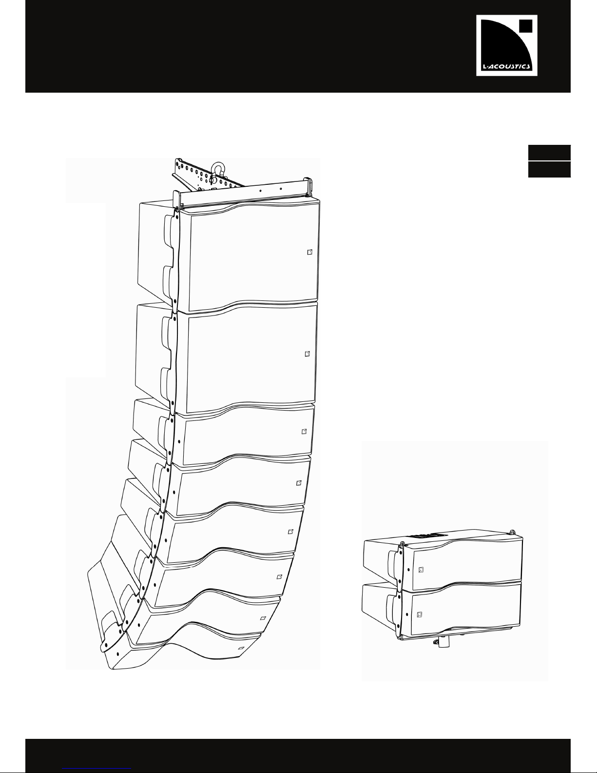
The rigging structure L-ACOUSTICS®KIBU is to be used solely for rigging with L-ACOUSTICS®KIVA and KILO
enclosures in vertical ‘‘Line Source’’ configurations.
The KIBU is provided with 2 shackles, each one has a safety cotter pin and can support up to 630kg (1388 lbs) with an
ultimate strength safety factor of 5:1. Using the provided shackles makes it possible to fly the KIVA system using 1 or 2
rigging point(s).
Figure 2: Rigging structure KIBU
KIBU is capable of rigging a maximum amount of weight of 266Kg / 586 lbs (in accordance with BGV-C1 standard).
According to the angle selected between each enclosure when installing the KIVA system, the mechanical stresses
within the system must be checked, so as to respect the following limits:
Up to 12 KIVA enclosures or 9 KILO enclosures or a maximum combination of 6 KIVA and 2 KILO
can be flown within any chosen angular configuration.
In order to use the KIVA system for up to 20 KIVA enclosures or 14 KILO enclosures or a maximum
combination of 12 KIVA and 4 KILO, the user must check that the system conforms to the
configuration chosen using SOUNDVISION simulation software
(see section ‘‘Mechanical Data’’ in the ‘‘SOUNDVISION’’ manual).
KIBU can also be used as a ground stacking platform for a configuration of standalone KIVA or KIVA and KILO
combination within the following limits:
A maximum of 4 KIVA or 2 KILO or a combination of the two is not to exceed a maximum of 0.78m
(30.7’’) in height if the KIBU is placed on the ground without securing it to the surface.
A maximum of 10 KIVA or 5 KILO or a combination of the two is not to exceed a maximum of
1.84m (72.4’’) in height when the KIBU is securly fastened to a surface.
It is the responsibility of the user to verify that the system is securely fixed to a stable flat surface and
is tested to make sure that the column of enclosures is stable and secure before each use.
!