Lütze DIOLINE20 User manual

1/45
Ethernet/IP bus interface
for DIOLINE20
Operating instructions
Version 1.00
January 2010

2
Lütze GmbH reserves the right to make modifications to their products in the interests of technical
progress. Such changes will not necessarily be recorded in each individual case.
This manual and the information contained therein have been put together with due care.
However, Lütze accepts no liability for printing errors or other errors, or damage caused as a
result of any such errors.
The brands and product names cited in this manual are trademarks or registered trademarks
belonging to the respective titleholder.
Copyright 2010 by Friedrich Lütze GmbH & Co. KG. All rights reserved.
How to contact us
Friedrich Lütze GmbH & Co. KG
Postfach 1224
D-71366 Weinstadt-Großheppach
Germany
Telephone –reception: ++49/ (0)7151/ 6053-0
Fax: ++49/ (0)7151/ 6053-277
Website address: http://www.luetze.de

Ethernet/IP bus interface for DIOLINE20 Vers. 1.00 Contents
3/45
Contents
1Safety instructions.........................................................................5
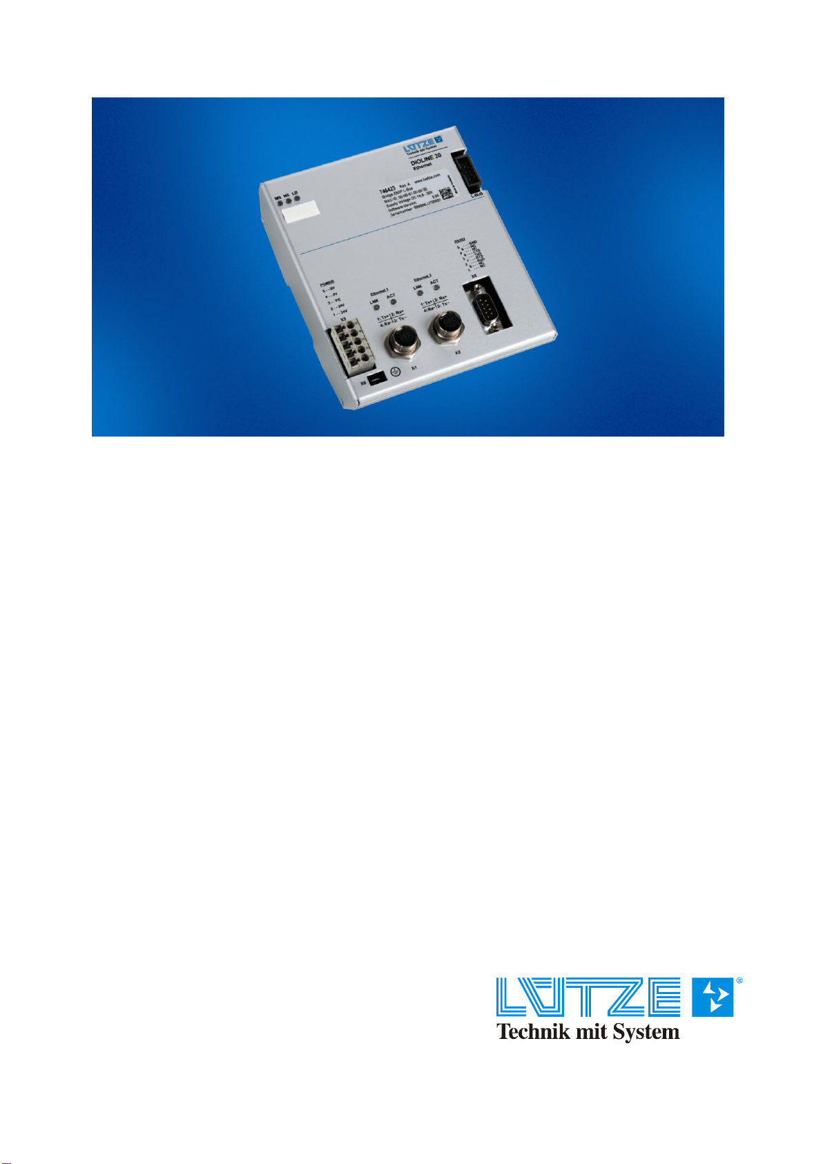
2Product overview of DIOLINE20 ...................................................9
3Housing/dimensions....................................................................10
4Description of device...................................................................11
4.1 Technical data of Ethernet/IP bus interface for DIOLINE20..............................12
4.2 Hardware description........................................................................................14
4.2.1 .Block diagram of the Ethernet/IP bus interface for DIOLINE20...................................................14
4.2.2 .Power supply................................................................................................................................15
4.2.3 .Description of Ethernet interfaces................................................................................................16
4.2.4 .RS232 interface............................................................................................................................17
4.2.5 .Indicators......................................................................................................................................18
4.3 Functional description.......................................................................................19
4.3.1 .Introduction...................................................................................................................................19
4.3.2 .L-Bus............................................................................................................................................20
4.3.3 .Ethernet/IP ...................................................................................................................................20
4.3.3.1 Common Industrial Protocol (CIP).............................................................................21
4.3.3.1.1 Supported objects..................................................................................................21
4.3.3.1.2 Supported services................................................................................................32
4.3.3.2 TCP/UDP (IPv4) ........................................................................................................32
4.3.3.3 DHCP.........................................................................................................................32
4.3.3.4 BOOTP......................................................................................................................32
4.3.3.5 IGMP..........................................................................................................................32
4.3.3.6 ICMP..........................................................................................................................32
4.3.4 .I/O design.....................................................................................................................................33
4.3.5 .Safety concept..............................................................................................................................34
4.3.6 .State of LED indications...............................................................................................................35
4.3.7 .Network and CIP configuration ....................................................................................................36
4.3.8 .Monitor program...........................................................................................................................37
4.3.9 .EDS..............................................................................................................................................38
5References ...................................................................................43
6Notes on operating digital output modules ...............................44
7Revision history...........................................................................45

Ethernet/IP bus interface for DIOLINE20 Vers. 1.00 Contents
4/45
Index of figures
Fig. 1: DIOLINE20 housing of Ethernet/IP bus interface........................................................................10
Fig. 2: Block diagram of the Ethernet/IP bus interface for DIOLINE20..................................................14
Fig. 3: Power supply terminals ...............................................................................................................15
Fig. 4: Pin assignment of power supply terminal....................................................................................15
Fig. 5: LED indications............................................................................................................................18

Ethernet/IP bus interface for DIOLINE20 Vers. 1.00 Safety instructions
5/45
1 Safety instructions
Importance of operating instructions
The operating instructions are an integral part of the DIORAIL module product and must be kept ready
to hand at all times. This applies until the module is disposed of. If the module is sold or lent out, the
operating instructions must be passed on with it.
Copyright
These operating instructions are only intended for the operator and its staff. The contents of these
instructions may not be forwarded, reproduced, used or otherwise imparted, either in full or in part,
without express permission.
Infringements may result in criminal convictions.
Disclaimer
We have checked the contents of this document for conformity with the hardware and software
described. Nevertheless, as discrepancies cannot be ruled out we do not accept liability for complete
conformity. The information in this document is checked regularly and any necessary corrections are
made in the subsequent editions. We are grateful for any suggestions for improvements.
Friedrich Lütze GmbH & Co. excludes all liability for damage caused by a lack of or insufficient
familiarity with the operating instructions. The operator is therefore advised to get written confirmation
that staff are fully versant with the instructions.
Modifications or functional changes to the Ethernet/IP bus interface for DIOLINE20 are not permitted
for safety reasons. Modifications to the Ethernet/IP bus interface for DIOLINE20 not expressly
approved by the manufacturer will thus forfeit any liability claims against Friedrich Lütze GmbH & Co.
The same applies if non-original parts or equipment, or parts and equipment not approved by us, are
used.
Correct use
Correct use means proceeding as described in the operating instructions.
The Ethernet/IP bus interface for DIOLINE20 may only be used for the scenarios provided for in the
technical documents and only in conjunction with the third-party equipment and components
recommended and approved by us.
Correct and safe operation of the product assumes proper transport, proper storage, assembly and
installation and careful operation and maintenance.

Ethernet/IP bus interface for DIOLINE20 Vers. 1.00 Safety instructions
6/45
Qualifications of staff
Only qualified staff may perform the following work on DIORAIL modules:
Installation
Commissioning
Operation
Maintenance
Qualified staff in the context of the safety instructions are people who are authorised to commission,
earth and label devices, systems and circuits in accordance with the standards for safety engineering.
The operating staff must be briefed and trained accordingly.
Maintenance of the Ethernet/IP bus interface for DIOLINE20
The Ethernet/IP bus interface for DIOLINE20 itself is maintenance-free. No inspection or maintenance
intervals are therefore required for ongoing operation.
Decommissioning and disposal of the Ethernet/IP bus interface for DIOLINE20
The operating company must observe the environmental guidelines of the respective country
applicable to the site when decommissioning and disposing of the Ethernet/IP bus interface for
DIOLINE20.
A material list is contained in the appendix.

Ethernet/IP bus interface for DIOLINE20 Vers. 1.00 Safety instructions
7/45
Explanation of symbols in the operating instructions
The operating instructions contain instructions that must be followed to ensure personal safety and
avoid damage to property. These instructions are indicated by a warning triangle and graded
according to the degree of hazard.
Immediate hazard
to the life and health of people.
Failure to observe these will result in death or extremely serious injuries
(crippling).
Potential hazard
to the life and health of people.
Failure to prevent it may result in death or extremely serious injuries.
Potentially dangerous situation
Minor injuries may result if it is not averted.
This symbol is also used as a warning against damage to property.
Instructions for correct handling
Designate a situation that could potentially result in damage.
Failure to observe these instructions may cause damage to the product or
something in its vicinity.
Environmental protection
Failure to comply with this notice may harm the environment.
Gefahr
Warnung
Vorsicht
i

Ethernet/IP bus interface for DIOLINE20 Vers. 1.00 Safety instructions
8/45
Further safety instructions
The Ethernet/IP bus interface for DIOLINE20 corresponds to the current state of the art and complies
with the applicable safety regulations and the relevant harmonised
European standards (EN).
Users must observe:
Pertinent accident prevention regulations
EC directives or other country-specific regulations
Generally recognised safety regulations
General ESD regulations.
The modules must be disconnected from the power supply when carrying out installation or
maintenance work (disconnect the mains plug). This can prevent accidents caused by electrical
voltages.
If electrical welding work is carried out on frames on which electrical modules
are mounted, all connections to and from these modules must first be
disconnected. This is the only way to protect the modules from being
destroyed by equalising currents.
Faults of any kind or any other kind of damage must be reported to a responsible person.
Protective and safety devices must not be bypassed or bridged. Dismantled safety devices must be
reassembled before commissioning again and must be subjected to a function test.
The modules must be secured against inappropriate or accidental use.
Original information signs, labels, stickers or similar must always be heeded and kept in a legible
state.
A DC 24 V power pack is used to supply power to the Ethernet/IP bus interface for DIOLINE20.
The operating voltage of DC 24 V is categorised as SELV (safety extra low voltage) and is thus not
subject to the EC Low Voltage Directive. Usage of other power supplies is not allowed.
The power is fed to the Ethernet/IP bus interface for DIOLINE20 at X3. The logics supply for the
expansion modules is fed on via the L-Bus ribbon cable from interface to interface.
Vorsicht

Ethernet/IP bus interface for DIOLINE20 Vers. 1.00 Product overview
9/45
2 Product overview of DIOLINE20
The Ethernet/IP bus interface is a connector between the Ethernet and the DIOLINE20 interface
modules.
The DIOLINE20 modules have been designed for use in rail vehicles.
A module network consists of the standardised controller core as the head of each network and a
maximum of 10 additional expansion modules from the DIOLINE20 family. The expansions are
connected by a flat conductor from interface to interface.
A loose connector without flat conductor is enclosed with the Ethernet/IP head. This is intended to
protect the contacts of the expansion slot in the last module of the network.
The DIOLINE20 product family is comprised of a multitude of combinable
interface types.
There are both digital and analogue input and output modules.
The description of the interfaces is enclosed with the respective modules.
i

Ethernet/IP bus interface for DIOLINE20 Vers. 1.00 Description of device
10/45
3 Housing/dimensions
Fig. 1: DIOLINE20 housing of Ethernet/IP bus interface

Ethernet/IP bus interface for DIOLINE20 Vers. 1.00 Description of device
11/45
4 Description of device
The technology
The Ethernet/IP bus interface for DIOLINE20 is based on a microcontroller with an integrated field bus
connection.
Both the digital and analogue I/O modules are activated by this basic module.
The system can be used in terminal boxes and control cabinets for mounting on a top hat rail.
Configuration of connections:
Power supply via 24 V connection (X3).
PE contact (X0)
Ethernet bus by means of 4-pin M12 female connectors (X1 and X2)
RS232 interface for designing with SUB-D connector (X4)
Connection to expansion modules by ribbon cable (L-Bus).
Potential applications
The Ethernet/IP bus interface for DIOLINE20 is a bus connection module for connection to the
Ethernet process bus (network) compliant to IEEE 802.3 10/100BaseTx.

Ethernet/IP bus interface for DIOLINE20 Vers. 1.00 Description of device
12/45
4.1 Technical data of Ethernet/IP bus interface for DIOLINE20
Process bus
interface:
Bus system:
Ethernet compliant to
IEEE 802.3
10/100BaseTx
Module type:
Ethernet/IP
communication adapter
Transmission medium:
2 x twisted pair cat. 5
compliant to IEEE
standard
Bus connection:
4-pin M12 socket
D-coded (X1 and X2)
Field bus interface:
L-Bus bus system
Maximum 10 I/O
modules can be
connected to the
L-Bus interface.
RS232 interface:
X4:
Male multipoint
connector, SUB-D,
9-pin UNC (M3 optional)
Environmental test:
EMC emitted
interference/
interference immunity:
EN 50121-3-2
Insulation coordination:
EN 50124-1
Vibration/shock
resistance:
EN 61373
Category 1
Class B
Cold/hot/climate
EN 50155
Supply unit:
Supply voltage:
24 V DC (range
16.8 V - 30.0 V)
Residual ripple:
max. ±10 %
Charging rate at
DC 24 V:
nom. 140 mA
at 16.8 V DC
200 mA plus charging
rate of individual I/O
interface;
protected in the event of
a malfunction (internal
short circuit or overload
at L-Bus connector)
by 2 A fuse
(10*INfor 100 ms or 5*IN
for 1s).
If optional configuration
is used without internal
fuse, then the power
supply must be
appropriately protected
by an external fuse.
Connected by 5-pin cage
tension spring X3 with
pressure point
Polarity reversal
protection: yes
Potential isolation:
Cutoff voltages:
Ethernet/IP and
electronic
AC 1500 V
RS232 and electronic
AC 500 V

Ethernet/IP bus interface for DIOLINE20 Vers. 1.00 Description of device
13/45
Diagnostics:
3 LEDs for following
status displays:
Module status MS,
Network status NS,
L-Bus status LB
LEDs for link and activity
compliant to the
Ethernet standard
for each interface
Other:
Module size:
141.5 x 123 x 36 mm
Weight (without
connector):
430 g
Housing: Aluminium
IP rating: IP 20
Mounting on a top hat rail
Installation position: all
installation positions
allowed
Operating temperature:
-40 to +70 °C
(+85 °C for 10 min),
complies with EN 50155
Class Tx
Storage temperature:
-40 to +85 °C
Relative humidity
100 %, brief moisture
condensation permissible
Optional conversion kit of
threads on Sub-D
connector UNC4/40 in
M3

Ethernet/IP bus interface for DIOLINE20 Vers. 1.00 Description of device
14/45
4.2 Hardware description
4.2.1 Block diagram of the Ethernet/IP bus interface for DIOLINE20
Fig. 2: Block diagram of the Ethernet/IP bus interface for DIOLINE20

Ethernet/IP bus interface for DIOLINE20 Vers. 1.00 Description of device
15/45
4.2.2 Power supply
A DC voltage of 24 V DC must be used for the power supply in accordance with the railway
specification EN 50155.
The X3 terminal for the power supply is designed as a
5-pin slot-in terminal with a cage tension spring.
6.3 mm flat-pin connector X0
for PE contact
Fig. 3: Power supply terminals
Pin no.
Signal
Description
1
24 V
24 V supply
2
24 V
24 V supply
3
PE
Earth connection
4
0 V
0 V supply
5
0 V
0 V supply
Fig. 4: Pin assignment of power supply terminal
The device must not be operated without the protective conductor connected,
as the housing could be live if the device is faulty.
Warnung
4
5
3
2
1

Ethernet/IP bus interface for DIOLINE20 Vers. 1.00 Description of device
16/45
4.2.3 Description of Ethernet interfaces
The standard connection of modules to the Ethernet is by two 4-pin M12 female connectors compliant
to IEC 61076-2-101-A1.
The Ethernet network connections are on the bottom at the front: X1 and X2.
Ethernet 1 connection
Pin no.
Signal
Description
The X1
"Ethernet 1" connector is
a 4-pin M12 socket
1
TX+
Send data +
2
RX+
Receive data +
3
TX+
Send data -
4
RX-
Receive data -
Housing
connector
PE
Shield
(connected to the housing)
Ethernet 2 connection
Pin no.
Signal
Description
The X2
"Ethernet 2" connector is
a 4-pin M12 socket
1
TX+
Send data +
2
RX+
Receive data +
3
TX+
Send data -
4
RX-
Receive data -
Housing
connector
PE
Shield
(connected to the housing)
The Ethernet 1 and Ethernet 2 interfaces each occupy one port of an internal Ethernet switch.

Ethernet/IP bus interface for DIOLINE20 Vers. 1.00 Description of device
17/45
4.2.4 RS232 interface
The "RS232" X4 connector is a 9-pin SUB-D male multipoint connector.
Pin assignment:
Pin no.
Signal
Description
1
NC
Not used
2
RXD
Receive Data
3
TXD
Transmit Data
4
NC
Not used
5
GND
Ground
6
NC
Not used
7
RTS
Not used
8
CTS
Not used
9
NC
Not used
Housing
connector
PE
Shield (connected to the housing)
1
2
3
4
59
8
7
6

Ethernet/IP bus interface for DIOLINE20 Vers. 1.00 Description of device
18/45
4.2.5 Indicators
The Ethernet/IP bus interface for DIOLINE20 has the following LEDs to display the current module
status:
Fig. 5: LED indications
LED
Colour
Meaning
MS
green/red
Module status
NS
green/red
Network status
LB
green/red
L-Bus status
Ethernet 1
LNK
green
Ethernet 1 Link status
ACT
yellow
Ethernet 1 Activity status
Ethernet 2
LNK
green
Ethernet 2 Link status
ACT
yellow
Ethernet 2 Activity status

Ethernet/IP bus interface for DIOLINE20 Vers. 1.00 Functional description
19/45
4.3 Functional description
4.3.1 Introduction
The module is used as a bus connector between the realtime Ethernet network "Ethernet/IP" (see [1])
and the Lütze field bus, referred to here as "L-Bus". The physical I/O functionality is provided by the
DIOLINE20 modules connected to the L-Bus.
The digital and analogue process data read via the Ethernet/IP or L-Bus are thereby transferred
completely and consistently on the L-Bus or Ethernet/IP.
The L-Bus is transparent to the Ethernet/IP network, i.e. the module acts, with regard to the I/O
technical data sets, as a highly flexible I/O module that can be individually configured within a wide
range.

Ethernet/IP bus interface for DIOLINE20 Vers. 1.00 Functional description
20/45
4.3.2 L-Bus
The L-Bus is a proprietary field bus from Lütze and is used to connect the single I/O submodules
(DIOLINE20 modules).
All process data and status information from this bus are consistently mapped asynchronously on the
Ethernet/IP; therefore, from the perspective of the other Ethernet/IP users, the L-Bus is transparent.
4.3.3 Ethernet/IP
Ethernet/IP is a realtime Ethernet network protocol based on standard TCP/IP and implemented by
the Common Industrial Protocol (CIP) of the (common) application layer.
The modules functions as an Ethernet/IP adapter of "communication adapter" subscriber class (see
[1]) and therefore supports the following features:
Communicates messages (explicit communication of Transport Class 3)
Communicates messages in realtime (process data) (implicit (multicast) communication of
Transport Class 1)
Supports both input-only and output-only connections
Supports configuration assembly
Supports Electronic Key Management
Supports Repeated Packet Interval (RPI) >= 20 ms
Supports Quality of Service (QoS) for implicit messages
Supports star and line shaped network topologies
Other manuals for DIOLINE20
1
Table of contents