Manual-4
RECALLING DELAYS
Press RECALL to copy from the Memory shown to the active set-
ting for the selected channel. If LINK is active, both channels will
be recalled. is will overwrite any current settings.
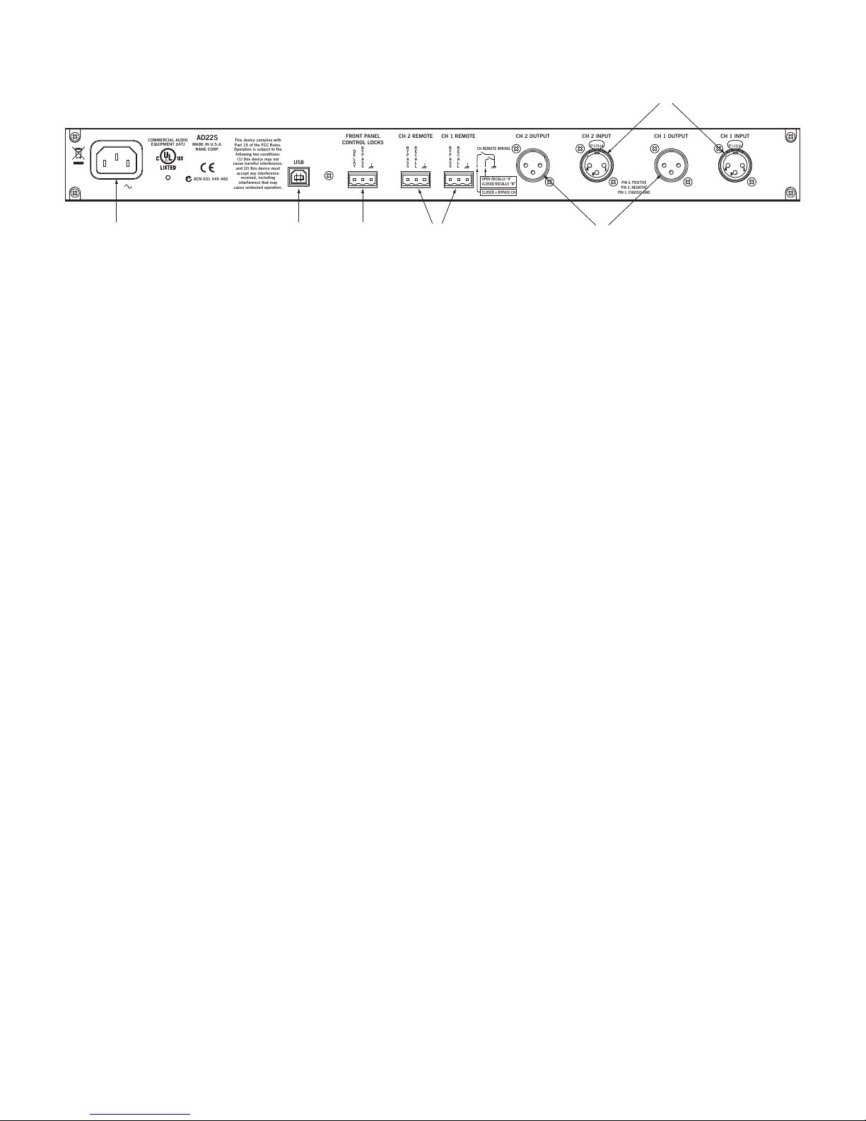
REMOTE RECALL
e REMOTE RECALL terminals on the rear of the unit are
functionally equivalent to the RECALL button. With a switch
wired between the RECALL terminal and the GND terminal,
close the switch to recall Memory B. Open the switch to recall
Memory A.
FIRMWARE UPDATE
Should a rmware upgrade become available, it will be posted on
the AD22S page at www.rane.com/ad22s.html. e USB port pro-
vides the connection to a PC enabling the le transfer. Perform
the following steps to update:
1. Ensure the unit is powered.
2. Connect via device cable to USB port on computer.
3. AD22S appears as an EXTERNAL DISK device containing
one le (named “AD22S_XX.BIN” or similar).
4. Delete this le. NOTE: After deleting this le, the folder may
disappear, then re-open after a few seconds.
5. Copy or drag the new rmware le to the AD22S.
6. After transfer, the AD22S restarts automatically and briey dis-
plays the new revision info. It may also reappear as an EXTER-
NAL DISK on the PC containing the new rmware le.
7. Disconnect USB cable and resume normal operation.
Notes: If the revision number displayed does not match the new
rmware, make sure you have the latest le and try again.
Tip: Press and hold both CURSOR buttons simultaneously
for one second to view the currently running rmware version.
If an error occurs during transfer or a le is corrupted, the
AD22S will revert to the last working version.
OPERATING DETAILS
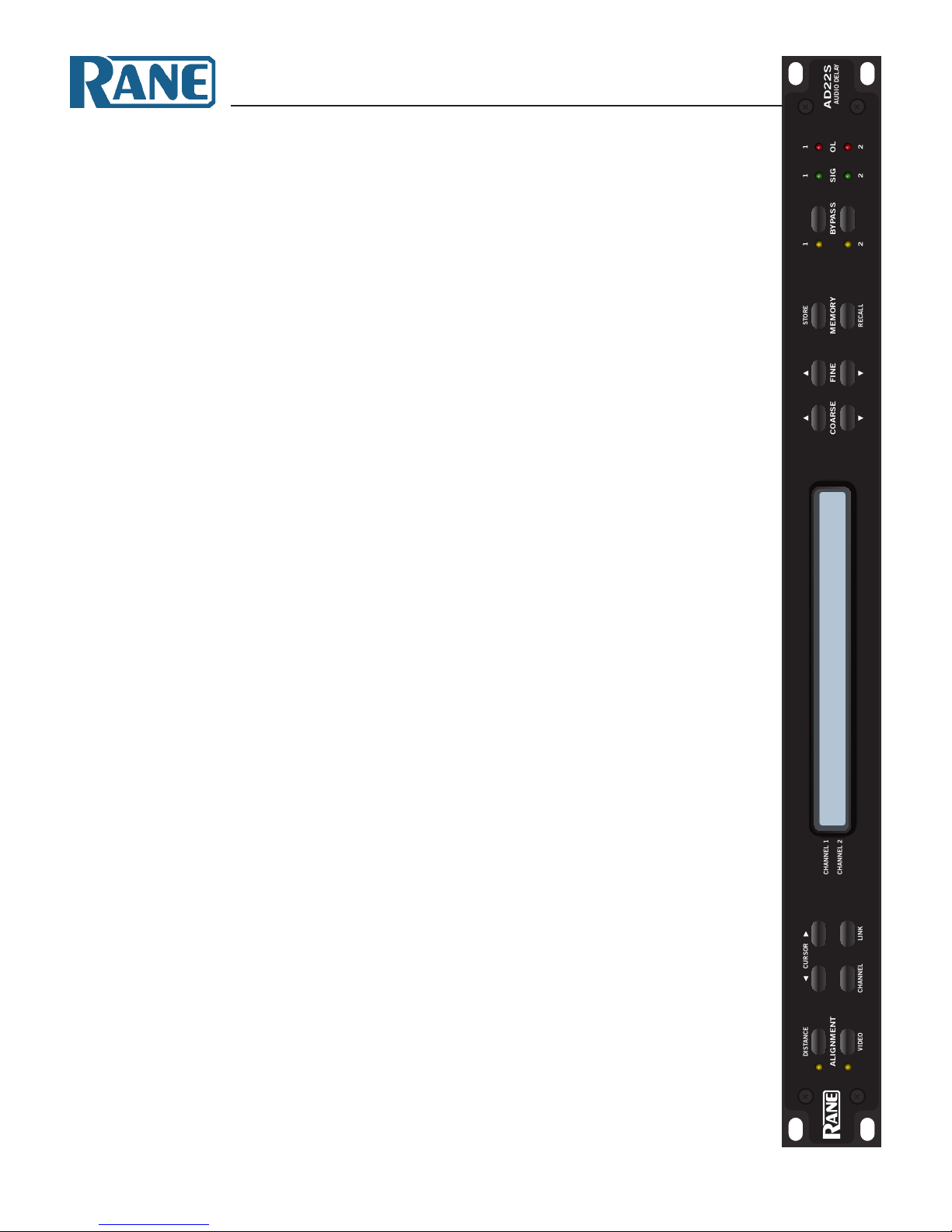
INITIAL SETUP
e AD22S is always on while plugged in. When rst powered
up, the LCD briey displays the words “Rane AD22S Audio
Delay” and the current rmware revision. Out of the box, both
channels are in BYPASS mode with the inputs routed directly to
the outputs. is makes it easy to set up and verify that signals are
present before turning on any delay. e yellow bypass indica-
tors mean that BYPASS is active; press each BYPASS button to
disable.
ALIGNMENT MODE
Two modes of operation are available. If working with video and
wish to set delay by number of frames, press VIDEO for video
alignment. Otherwise press DISTANCE for distance alignment.
Both modes oer milliseconds as a simple display option in addi-
tion to their distance or video functions.
SETTING THE DELAY
A ‘>’ by the channel number indicates the channel is selected for
editing. is appears on both channels if LINK is active.
Distance Mode: Use CURSOR buttons to highlight the unit
type, then select between milliseconds, feet, or meters. e
AD22S also needs to know the temperature. To set, select and set
the unit type to °C or °F, then select and set the temperature.
Video Mode: Choose between frames or milliseconds as the dis-
play setting. For frames, the delay value is based on the number of
frames per second, denoted by “fps” on the display. Set this rst
and make sure it matches your video frame rate.
Linked Channels: With channels linked, any changes made are
applied to both channels at once. is does not force the delay
values to be the same.
Example: For two speaker arrays at dierent distances from a
performer, linking the two channels lets you change temperature
settings for both at once.
For stereo operation, set each channel to the same value before
pressing LINK.
STORING DELAYS
e *character on the display means the current setting dif-
fers from the memory bank shown. Move the CURSOR to the
memory eld, then press COARSE or FINE to toggle between
Mem A or Mem B. Press STORE to copy the current setting into
this location. Note that *is no longer displayed. If channels are
linked, both channels will be stored.
Note: e CURSOR must be on the Memory Bank eld to
STORE. is is to prevent an accidental overwrite of saved set-
tings.
©Rane Corporation 10802 47th Ave. W., Mukilteo WA 98275-5000 TEL 425-355-6000 FAX 425-347-7757 WEB rane.com
111803