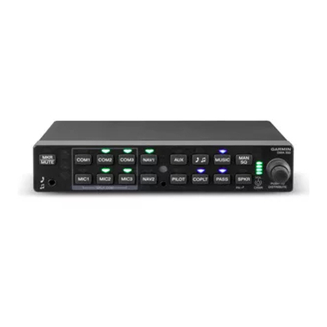
L3 Aviation Products Lynx NGT-9000 Technical specifications

FAIRCHILD SA227-AC
AC-583
N3114G

Airplane Flight Manual Supplement or Supplemental Flight Manual for the NGT-9000
(
Revision(4(Issue: 9/19/17(Page(2(of(27(Document(Number(L3-76AK-AFMS1(
FAA(Approved
FAA APPROVED
AIRPLANE FLIGHT MANUAL SUPPLEMENT
or
SUPPLEMENTAL FLIGHT MANUAL
For The
L3 Aviation Products
Lynx Multilink Surveillance System
Models NGT-9000
L3 Part Number 9029000-20000
RECORD OF REVISIONS
Revision
Date of Revision
Description
Original
3/31/2015
Original Issue
1
6/19/2015
Typographical error corrections
Corrections to Table 3-1 in section 3.2.1
2
3/27/2016
Incorporation of s/w Revision 2.0: ATAS and
TAWS
3
2/24/2017
Updated for s/w Version 2.1
4
9/19/2017
Updated for s/w Version 3.x

Airplane Flight Manual Supplement or Supplemental Flight Manual for the NGT-9000
(
Revision(4(Issue: 9/19/17(Page(3(of(27(Document(Number(L3-76AK-AFMS1(
FAA(Approved
This page intentionally left blank

Airplane Flight Manual Supplement or Supplemental Flight Manual for the NGT-9000
(
Revision(4(Issue: 9/19/17(Page(4(of(27(Document(Number(L3-76AK-AFMS1(
FAA(Approved
TABLE OF CONTENTS
SECTION 1.!GENERAL ........................................................................................................... 6!
1.1!Functional Description ................................................................................................... 6!
1.2!NGT-9000 ADS-B Traffic Advisory System (ATAS) [Optional] ...................................... 7!
1.3!NGT-9000 Terrain Awareness and Warning System (TAWS) [Optional] ...................... 7!
1.4!NGT-9000+ Traffic Awareness Overview [Optional] ...................................................... 8!
1.5!NGT-9000D Antenna Diversity Overview [Optional] ...................................................... 8!
1.6!Capabilities .................................................................................................................... 8!
1.7!L-Band UAT Antenna ..................................................................................................... 9!
1.8!GPS Antenna and the MSS Internal GPS Receiver ...................................................... 9!
1.9!Configuring the NGT-9000 ............................................................................................. 9!
1.10!Personal Electronic Devices .......................................................................................... 9!
1.11!Weather Displays ........................................................................................................... 9!
1.12!Lightning Detection (Optional) ....................................................................................... 9!
1.13!Traffic Displays ............................................................................................................. 10!
1.14!Interaction of Major Components ................................................................................. 12!
1.15!Installation Configuration for This Aircraft .................................................................... 13!
SECTION 2.!LIMITATIONS ................................................................................................... 14!
2.1!Minimum Documentation ............................................................................................. 14!
2.2!Minimum Equipment .................................................................................................... 14!
2.3!ADS-B OUT Compliance.............................................................................................. 14!
2.4!IDENT Function............................................................................................................ 14!
2.5!ALT Function ................................................................................................................ 14!
2.6!Standby Function ......................................................................................................... 14!
2.7!Traffic Awareness ........................................................................................................ 14!
2.8!Terrain Awareness ....................................................................................................... 15!
2.9!Applicable System Software ........................................................................................ 15!
SECTION 3.!EMERGENCY PROCEDURES ......................................................................... 16!
3.1!Emergency Procedures ............................................................................................... 16!
3.2!Abnormal Procedures .................................................................................................. 17!
SECTION 4.!NORMAL PROCEDURES ................................................................................ 26!
4.1!Normal Power ON ........................................................................................................ 26!
SECTION 5.!PERFORMANCE .............................................................................................. 26!
SECTION 6.!WEIGHT AND BALANCE ................................................................................. 26!
SECTION 7.!SYSTEM DESCRIPTIONS ................................................................................ 26!
7.1!Pilot’s Guide ................................................................................................................. 26!
7.2!Traffic Sources ............................................................................................................. 26!
7.3!Weather Sources ......................................................................................................... 26!
7.4!Lightning Detection Sources [Optional] ........................................................................ 27!
7.5!Power ........................................................................................................................... 27!
7.6!External Switches, Lights and Controls [Optional] ....................................................... 27!
Airplane Flight Manual Supplement or Supplemental Flight Manual for the NGT-9000
(
Revision(4(Issue: 9/19/17(Page(5(of(27(Document(Number(L3-76AK-AFMS1(
FAA(Approved
TABLE OF FIGURES
Figure 1-1: Lynx NGT-9000 ......................................................................................................... 6!
Figure 1-2: Typical NGT-9000 Traffic Screen ........................................................................... 10!
Figure 1-3: NGT-9000 Connections and Functions ................................................................... 12!
Figure 1-4: Installation Configuration Data ................................................................................ 13!
TABLE OF TABLES
Table 1-1: Typical Target Symbology ........................................................................................ 11!
Table 2-1: Required Equipment ................................................................................................ 14!
Table 2-2: Software Version ...................................................................................................... 15!
Table 3-1: Troubleshooting for the Panel Mount NGT-9000 ..................................................... 17!
Table 7-1: Light and Switch Functions ...................................................................................... 27!
Airplane Flight Manual Supplement or Supplemental Flight Manual for the NGT-9000
(
Revision(4(Issue: 9/19/17(Page(6(of(27(Document(Number(L3-76AK-AFMS1(
FAA(Approved
SECTION 1. GENERAL
1.1 Functional Description
The Lynx MultiLink Surveillance System (also referred to in this manual as the Lynx NGT-9000)
is a Mode S Level 2 dens Class 1 Transponder with an integrated GPS receiver providing
Automatic Dependent Surveillance-Broadcast (ADS-B) output using a 1090ES (Extended
Squitter). The unit also receives ADS-B data via 1090ES and UAT (978 MHz Universal Access
Transceiver). Figure 1-1 is a depiction of the NGT-9000.
The unit replies to Mode A, Mode C and Mode S interrogations receiving interrogations at 1030
MHz and transmitting responses at 1090 MHz. The unit is equipped with IDENT capability that
activates the Special Identification (SPI) pulse for 18 seconds.
Ground stations can interrogate Mode S Transponders individually using a 24-bit ICAO Mode S
address, which is unique to the particular aircraft. In addition, ground stations may interrogate
the unit for its transponder data capability and the aircraft's Flight ID.
The ADS-B provides own aircraft data with Enhanced Visual Acquisition (EVAcq) traffic
information that improves situational awareness and flight safety by providing aircraft position,
velocity, and heading information that is automatically transmitted from other aircraft and ground
stations providing immediate surveillance of air-to-air traffic.
In addition to ADS-B surveillance, the installed NGT-9000 includes an Active Traffic Awareness
System (TAS/TCAS), ADS-B Traffic Advisory System (ATAS) and Terrain Awareness and
Warning System (TAWS), as well as support for both top and bottom antenna diversity.
The 1090ES and UAT ADS-B data link have the following capabilities:
• 1030MHz/1090 MHz In – Receive ADS-R and TIS-B
• 1090ES OUT – Transmits 1090 MHz Extended Squitter ADS-B
• UAT IN – Receives 978 MHz ADS-B, ADS-R and TIS-B, FIS-B, NOTAMS, and TFR’s
Figure 1-1: Lynx NGT-9000

Airplane Flight Manual Supplement or Supplemental Flight Manual for the NGT-9000
(
Revision(4(Issue: 9/19/17(Page(7(of(27(Document(Number(L3-76AK-AFMS1(
FAA(Approved
1.2 NGT-9000 ADS-B Traffic Advisory System (ATAS) [Optional]
The ADS-B Traffic Advisory System (ATAS) is a passive system that monitors ADS-B, ADS-R
and TIS-B ADS-B IN data and alerts the flight crew via on-screen alerts aural traffic calls and an
optional Traffic Alert lamp to nearby aircraft and assists the pilot in the visual acquisition of
aircraft that may represent a danger. Refer to the Pilot's Guide, L3 p/n 0040-17000-01 Revision
H or later, for examples of on-screen symbology and aural alerts.
• The tracking of other aircraft is in a cylindrical volume centered on own aircraft with a
maximum radius of 20 nmi and extending 10,000 ft above and 10,000 ft below ownship.
• ATAS will track up to 60 intruders simultaneously.
• A Traffic Advisory (TA) is displayed when other aircraft are a potential threat.
• When ownship is in the airport environment, a Traffic Advisory (TA) is displayed 12.5 to
35 seconds prior to the CPA with another aircraft when the CPA is within 750 ft
horizontally and 300 ft vertically.
• A TA symbol remains on the screen for at least 8 seconds unless the respective track is
terminated.
• When the aircraft is outside the airport environment, aircraft that are within a range of 6
nmi of ownship with a vertical distance of +/- 1200 ft (if altitude is reporting) are classified
as a Proximate Advisory (PA). A PA is displayed only for aircraft that are in air.
• ATAS and TAS/TCAS may operate at the same time with traffic information being
correlated by the unit
When ATAS is installed, an Audio Acknowledge button will cancel the current aural
announcement.
1.3 NGT-9000 Terrain Awareness and Warning System (TAWS) [Optional]
The Terrain Awareness and Warning System (TAWS) is an optional function that is set up
during installation. The TAWS function continuously monitors the aircraft’s position, altitude,
speed, track, and phase of flight and compares the information to the terrain database loaded
during installation. Terrain and obstacle hazards are indicated by cautions and warnings using
screen annunciators, aural terrain alerts, and Terrain Caution and Warning alert lamps. Refer to
the Pilot's Guide, L3 p/n 0040-17000-01 Revision H, or later, for examples of on-screen
symbology and aural alerts.
The TAWS function uses Forward Looking Terrain Avoidance (FLTA) and Ground Proximity
Warning System (GPWS) functionality to determine when a terrain alert or altitude callout is
triggered due based on the following conditions:
• Reduced required terrain or obstacle clearance (FLTA)
• Imminent terrain impact (FLTA)
• Premature descent
• Excessive descent rate (GPWS)
• Negative climb rate or altitude loss after takeoff (GPWS)
• Passing an altitude of 500 ft (GPWS)

Airplane Flight Manual Supplement or Supplemental Flight Manual for the NGT-9000
(
Revision(4(Issue: 9/19/17(Page(8(of(27(Document(Number(L3-76AK-AFMS1(
FAA(Approved
There are four TAWS configurations available with the NGT-9000:
• Disabled
• TAWS B – Default Aural Phrases
• TAWS B – Alternate Aural Phrases
• Display Only – No Alerts
When a TAWS configuration is enabled with audio, an Audio Acknowledge button will cancel the
current aural announcement.
1.4 NGT-9000+ Traffic Awareness Overview [Optional]
The NGT-9000+ (“9000 Plus”) supports optional active Traffic Awareness System (TAS) and
Traffic Conflict Avoidance System (TCAS).
The TAS/TCAS options are active systems that operate as aircraft-to-aircraft interrogation
devices. The unit interrogates transponders in the surrounding airspace similar to ground based
radar. When replies to these active interrogations are received, the responding aircraft’s range,
altitude, and closure rates are computed to plot traffic location and predict collision threats. The
unit alerts the flight crew to nearby transponder equipped aircraft and assists the pilot in the
visual acquisition of aircraft that may represent a danger. Traffic information, out to a selected
range, is graphically displayed on the unit or alternate display. Refer to the Pilot's Guide, L3 p/n
0040-17000-01 Revision K or later, for examples of on-screen symbology and aural alerts for
each system.
• The system display shows the relative position of traffic using text, shapes (i.e., Traffic
Advisory = solid circle; Other Traffic = open diamond) and colors.
• The effective active-mode surveillance range is 35 nm and the system is capable of
tracking 35 Intruders simultaneously with the target bearing relative to the nose of own
aircraft.
• The tracking of targets is in a cylindrical volume centered on own aircraft that has, at a
minimum, a radius of 35 nm and extends 10,000 ft above and 10,000 ft below own
aircraft.
• The system uses a voice audio output that announces Traffic Advisory and relative
altitude (with optional Extended Call-outs enabled).
• The TCAS option qualifies as a TCAS I system and as such, offers only Traffic
Advisories (TA) (“Traffic, traffic. 12-O’clock, one mile”) but not Resolution Advisories
(RA) such as “Climb, climb”.
1.5 NGT-9000D Antenna Diversity Overview [Optional]
The NGT-9000D has the same hardware and firmware/software as the basic NGT-9000, but is
capable of supporting dual L-band antennas (one bottom and one top) to enhance system
performance and prevent fuselage blanking of a single bottom antenna in tight turns into a
ground station or UAT target. The upper L-band antenna may be a single blade antenna or the
optional Directional Antenna.
1.6 Capabilities
The NGT-9000 transceiver can be software configured as either an NGT-9000, 9000+, or
9000D. It can also be installed with, or without TAWS and peripheral ARINC-429 or RS-422
panel mounted traffic and weather displays.

Airplane Flight Manual Supplement or Supplemental Flight Manual for the NGT-9000
(
Revision(4(Issue: 9/19/17(Page(9(of(27(Document(Number(L3-76AK-AFMS1(
FAA(Approved
1.7 L-Band UAT Antenna
The L-Band antenna is used by the Lynx NGT-9000 to transmit and receive 1090 MHz ADS-B
and receive 978MHz ADS-B (UAT). At least one L-band antenna must be located on the
bottom of the aircraft.
1.8 GPS Antenna and the MSS Internal GPS Receiver
The GPS utilizes signals from Global Positioning System (GPS)
satellite constellation and
Satellite-Based Augmentation Systems
(SBAS). The MSS has an internal GPS function that
provides position, velocity, time and integrity (NIC, NAC, etc.) information to the ADS-B
functions. It is located on the top of the aircraft.
NOTE
The NGT-9000’s built-in GPS does not provide Ownship position for external
moving map displays
1.9 Configuring the NGT-9000
The unit’s configuration is preserved within the Data Configuration Module (DCM), which is
permanently attached to the aircraft and communicates with the NGT-9000 via a serial
connection. The configuration options are set up during installation and cannot be changed
except by a licensed installer.
NOTE
The NGT-9000’s configuration parameters can only be changed by a
licensed installer
1.10 Personal Electronic Devices
The Lynx NGT-9000 supports the use of personal electronic devices (e.g., iPad) via a Wi-Fi
connection. The PED must use approved applications that
support the ADS-B broadcast
services (i.e., ADS-B In, TIS-B, ADS-R, and FIS-B). Check with an L3 approved avionics
dealer or contact L3 Aviation Products for a current list of approved applications.
1.11 Weather Displays
NEXRAD, METARS, TAFS, PIREPS, NOTAMS and temperatures and winds aloft are displayed
on the NGT-9000 provided that the aircraft is within the service volume of a ground station.
Additionally, the same information can be displayed on approved weather displays can interface
with the NGT-9000 to
provide FIS-B weather information using the ADS-B IN link. Screen
information and controls may be different for each of the approved displays.
1.12 Lightning Detection (Optional)
The WX-500 Stormscope is a Weather Mapping System that provides lightning discharge
information. This information is shown on the right application screen of the NGT-9000 Panel
Mount unit. This function is available beginning with Software 2.1.

Airplane Flight Manual Supplement or Supplemental Flight Manual for the NGT-9000
(
Revision(4(Issue: 9/19/17(Page(10(of(27(Document(Number(L3-76AK-AFMS1(
FAA(Approved
1.13 Traffic Displays
The NGT-9000 will provide, at a minimum, UAT, TIS-B and ADS-R traffic on the unit’s built-in
display and can repeat this traffic information on any approved ARINC-429 or RS-422 display.
The NGT-9000+ can also display active Traffic Awareness System (TAS/TCAS) targets on the
unit’s built-in display and can repeat this traffic information on any approved ARINC-429 or RS-
422 display. Figure 1-2 Illustrates a typical traffic display on the NGT-9000 screen. Table 1-1
illustrates typical target symbology.
Refer to the Pilot's Guide, L3 p/n 0040-17000-01 Revision K, or later, for details on operation
and a description of how the information is depicted. Check with an L3 approved avionics
dealer or contact L3 Aviation Products for a current list of approved traffic displays.
Figure 1-2: Typical NGT-9000 Traffic Screen
1.13.1 Traffic Priority
Traffic is displayed on the screen using the following priority scheme:
1. TAS/TCAS Traffic Advisories (TA’s)
2. ATAS (ADS-B) Traffic Alerts
3. Selected Traffic
4. Proximate Advisories
5. Other Traffic
Traffic may also be prioritized according to phase of flight by using the ALT Mode toggle on the
left of the screen with:
• Normal (NRM) displaying traffic ± 2,700 ft relative to Ownship
• Above (ABV), or Takeoff Mode, displaying traffic +9,000 and -2,700 ft relative to
Ownship
• Below (BLW), or Landing Mode, displaying traffic +2,700 and -9,000 ft relative to
Ownship
• Unrestricted (UNR) or Enroute Mode, displaying traffic +9,900 and -9,900 ft relative to
Ownship

Airplane Flight Manual Supplement or Supplemental Flight Manual for the NGT-9000
(
Revision(4(Issue: 9/19/17(Page(11(of(27(Document(Number(L3-76AK-AFMS1(
FAA(Approved
Table 1-1: Typical Target Symbology
* To promote cockpit commonality, installation configuration options are available to set the
airborne PA & OT traffic color to either cyan or white.

Airplane Flight Manual Supplement or Supplemental Flight Manual for the NGT-9000
(
Revision(4(Issue: 9/19/17(Page(12(of(27(Document(Number(L3-76AK-AFMS1(
FAA(Approved
1.14 Interaction of Major Components
Figure 1-3 shows how the major components of the NGT-9000 connect to
other aircraft
systems.
Figure 1-3: NGT-9000 Connections and Functions

Airplane Flight Manual Supplement or Supplemental Flight Manual for the NGT-9000
(
Revision(4(Issue: 9/19/17(Page(13(of(27(Document(Number(L3-76AK-AFMS1(
FAA(Approved
1.15 Installation Configuration for This Aircraft
Figure 1-4 should be completed by a licensed installer.
Model NGT-9000: P/N 9029000-20000
Model NGT-9000+: P/N 9029000-20000
Model NGT-9000D: P/N 9029000-20000
Model NGT-9000D+: P/N 9029000-20000
Aircraft Specific
Tail Number:
Mode S Identifier (Octal):
Transponder Diversity: Disabled Enabled
TAS Enable: Disabled Enabled TCAS Enable: Disabled Enabled
TAS/TCAS Ground Filtering Altitude: Disabled Enabled
TAS/TCAS or ATAS Extended Callout Enable: Disabled Enabled
FIS-B Enable: Disabled Enabled Auto
TIS-B/ADS-R Service Status Indication Enable: Disabled Enabled
Normal (Prox/Other) Traffic Color: Cyan White
ATAS: Disabled Enabled
Terrain Display Enable:
Disabled
TAWS B – Default Aural Phrases
TAWS B – Alternate Aural Phrases
Display Only – No Alerts
WX-500 Enabled (Stormscope)
Disabled
Enabled – Bottom Antenna
Enabled – Top Antenna
Heading Source: Disabled Enabled
On Ground Discrete Installed: Not Installed Open – In Air Open – On Ground
In Air/On Ground
On Ground Discrete Installed: Not Installed Open – In Air Open – On Ground
Standby Input
Standby Discrete Installed: Not Installed Ground-Standby
Input/Output Configuration
RS-422 #1: External Display WX-500 L3 Protocol 1
RS-232 #1: WX-500 L3 Protocol 1
Wi-Fi: Disabled Enabled
Figure 1-4: Installation Configuration Data
N3114G
X
S0646563
X
X
X
X
X
X
X
X
X
X
X
X
X
X
X
X
N/a

Airplane Flight Manual Supplement or Supplemental Flight Manual for the NGT-9000
(
Revision(4(Issue: 9/19/17(Page(14(of(27(Document(Number(L3-76AK-AFMS1(
FAA(Approved
SECTION 2. LIMITATIONS
2.1 Minimum Documentation
The L3 Pilot’s Guide for the NGT-9000 Part Number 0040-17000-01 (Rev K, or later revision)
must be carried on board the aircraft at all times.
2.2 Minimum Equipment
The NGT-9000 must have the following system interfaces in Table 2-1 fully functional in order to
be compliant with the requirements for 14 CFR 91.225 and 91.227 ADS-B OUT operations:
Table 2-1: Required Equipment
Interfaced Equipment
Number
Required
Number
Installed
NGT-9000, NGT-9000+, NGT-9000D, or NGT-9000D+
With operable SBAS position source
1
1
2.3 ADS-B OUT Compliance
The NGT-9000 only complies with 14 CFR 91.227 when all its required functions are operational
as indicated by external annunciators not being illuminated and/or interfaced display ADS-B
messages not being present.
2.4 IDENT Function
The system must be capable of squawking IDENT when requested by Air Traffic Control.
2.5 ALT Function
While operating within airspace requiring an ADS-B OUT compliant transmitter, Pressure
Altitude Broadcast Inhibit (PABI), shall only be enabled when requested by Air Traffic Control.
2.6 Standby Function
The Standby Mode input is used to place the unit’s transponder into Standby. It is intended for
use when dual transponders are installed on the aircraft.
2.7 Traffic Awareness
Traffic Awareness and Traffic Alerting are intended as an aid to visual acquisition of conflicting
traffic and may not be used as the sole basis for aircraft maneuvering.
NOTE
Information shown on the display is provided to the pilot as an aid to visually acquiring traffic.
Pilots should maneuver their aircraft based only on ATC guidance or positive visual
acquisition of the conflicting traffic. Maneuver should be consistent with ATC instructions.
ATC should be contacted for resolution of the traffic conflict.

Airplane Flight Manual Supplement or Supplemental Flight Manual for the NGT-9000
(
Revision(4(Issue: 9/19/17(Page(15(of(27(Document(Number(L3-76AK-AFMS1(
FAA(Approved
2.8 Terrain Awareness
a. Navigation must not be predicated on the use of TAWS;
b. To avoid giving unwanted alerts, the TAWS must be inhibited when landing at an airport
that is not included in the airport database;
c. The use of the TAWS terrain warning and Terrain Display functions is prohibited during
QFE operations.
d. TAWS must meet the requirements of TSO-151c for Class B.
e. If unit is configured for Terrain Display Only (no aural alerts), then unit is not considered
a Class B TAWS.
2.9 Applicable System Software
This AFMS/SFM is applicable to the software versions shown in Table 2-2 or later FAA
approved version.
Table 2-2: Software Version
Software
Part No.
Version
NGT-9000 Ops s/w
9020010-( )
where 9020010-004 is the first
in the series
Rev 3.x
where Rev 3.0 is the first
in the series
68DC Navigational Database
North America (68.bin)
8010-22310-0001
Most current cycle1, 2
72DC Cultural Features Database
North American Extended (72.bin)
8010-12004-0001
Most current cycle2
71DC World Terrain Database
8010-23010-0001
Most current cycle2
1 Available from Jeppesen on 28-day cycles
2 There is no requirement to update this database because it is used only for informational purposes.

Airplane Flight Manual Supplement or Supplemental Flight Manual for the NGT-9000
(
Revision(4(Issue: 9/19/17(Page(16(of(27(Document(Number(L3-76AK-AFMS1(
FAA(Approved
SECTION 3. EMERGENCY PROCEDURES
3.1 Emergency Procedures
3.1.1 Terrain Warning Alert (Display Alert, Audio Alert, or Terrain Warning (Red) Lamp
TAWS Display PULL UP, Audio Alert of
“Terrain, Terrain; Pull Up, Pull UP” or
“Obstacle, Obstacle; Pull Up, Pull Up”
and/or Red Terrain Warning
Lamp……………..
IMMEDIATELY STOP DESCENT AND
BEGIN MAXIMUM PERFORMANCE RATE
OF CLIMB CONSISTENT WITH PHASE OF
FLIGHT.
CHECK TERRAIN CLEARANCE, OR
ATTEMPT TO VISUALLY ACQUIRE
OBSTACLE.
CONTINUE CLIMB UNTIL CLEAR OF
TERRAIN OR OBSTACLE
3.1.2 Terrain Caution Alert (Display Alert, Audio Alert, and/or Terrain Caution (Amber)
Lamp)
TAWS Display TERRAIN, Audio Alert of
“Caution Terrain, Caution Terrain” or
“Caution Obstacle, Caution Obstacle”
and/or Amber Terrain Warning Lamp………..
IMMEDIATELY STOP DESCENT AND
BEGIN A SAFE RATE OF CLIMB
CONSISTENT WITH PHASE OF FLIGHT.
CHECK TERRAIN CLEARANCE, OR
ATTEMPT TO VISUALLY ACQUIRE
OBSTACLE.
CONTINUE CLIMB UNTIL CLEAR OF
TERRAIN OR OBSTACLE
3.1.3 Loss Of Aircraft Electrical Power Generation (Loss of Generator)
Loss of electrical power generation .........................
REMOVE POWER FROM NGT-9000
If the NGT-9000 is shut down in order to shed load from the aircraft’s electrical system, ADS-B
OUT and ADS-B IN will no longer be available. If under ATC control, notify your Controller of
loss of ADS-B OUT.
NOTE
This guidance is supplementary to any procedure provided in the AFM
or POH for the aircraft in Loss of Power situations

Airplane Flight Manual Supplement or Supplemental Flight Manual for the NGT-9000
(
Revision(4(Issue: 9/19/17(Page(17(of(27(Document(Number(L3-76AK-AFMS1(
FAA(Approved
3.1.4 Loss of GPS/SBAS Position Data
Loss of GPS/SBAS indicated by a GPS failure
message on the NGT-9000/CP-2500 and a
SLOW blinking ADS-B FAIL light (if installed) .........
PULL NGT CIRCUIT BREAKER.
WAIT 5 SECONDS AND RESET. IF
SLOW BLINKING ADS-B FAIL LIGHT
CONTINUES, OR BECOMES STEADY,
ASSUME AN ADS-B OUT FAILURE.
If under ATC control, notify your Controller of loss of ADS-B OUT.
3.1.5 Visual/Aural Traffic Alert From ATAS, TAS or TCAS
Traffic Alert .............................................................
VISUALLY ACQUIRE TRAFFIC
3.2 Abnormal Procedures
3.2.1 Abnormal Indications
Table 3-1: Troubleshooting for the Panel Mount NGT-9000
Symptom
Screen
Cause/Corrective Actions
• Blank display.
• ADS-B Fail lamp is OFF
All
Loss of power or damaged unit.
1. Check power connections, breakers, and main
avionics switch.
2. Verify Battery (BAT) Master switch is on.
3. Check the Lynx MAT fault log.
Contact L3 Field Service before removal of unit.
The unit has manual
brightness adjustment only.
All
Loss of light sensor data.
1. Try clearing the failure by restarting the unit by
tapping the Restart button.
2. Check System Status Messages.
3. Check the Lynx MAT fault log.
Contact L3 Field Service before removal of unit.
When touching the screen,
the command function
seems to be slightly off from
the center of the screen
symbol or area.
All
The screen calibration is out of tolerance.
1. Perform the Screen Calibration has described in the
Installation Manual (L3-76AK-IM1).
Contact L3 Field Service before removal of unit.
Internal fan is always active.
MSG button on screen.
N/A
Loss of temperature sensor data. The message seen is
“Unit Over Temp Service Soon”.
1. Try clearing the failure by restarting the unit by
tapping the Restart button.
2. If in maintenance mode the fan remains active. This
is normal.
3. Check System Status Messages.
4. Check the Lynx MAT fault log.
Contact L3 Field Service before removal of unit.

Airplane Flight Manual Supplement or Supplemental Flight Manual for the NGT-9000
(
Revision(4(Issue: 9/19/17(Page(18(of(27(Document(Number(L3-76AK-AFMS1(
FAA(Approved
Table 3-1: Troubleshooting for the Panel Mount NGT-9000
Symptom
Screen
Cause/Corrective Actions
Message page contains
messages that do not
indicate a functional failure
on the system status page.
N/A
The following internal tests do not create a fail message
in the system status page.
• Configuration Module Test
• Configuration Module Configuration Validity
• Mutual Suppression Bus Self-Test
• Over-Temperature Monitor (in air)
• Power Fail Monitor
Although no immediate loss of function is occurring, an
undesired condition is taking place. At the earliest
convenience, perform the following action:
1. Try clearing the failure by restarting the unit by
tapping the Restart button (or cycling power).
Contact L3 Field Service before removal of unit.
Unit does not operate in
normal mode and starts in
Bootloader or maintenance
mode.
MSG button on screen.
N/A
The following internal hardware test failures cause the
unit to automatically reset. This happens without cycling
power to the unit. If the hardware failure being detected
does not clear, a system fail message is sent.
• ARINC 429 Receiver Loop Back Self-Test
• Panel Mount Refresh Display Test
• Panel Mount Frozen Display Test
• SDRAM Self-Test
• Persistent Memory Self-Test
• FPGA CBIT Test/Monitor
• System Clock Test/Monitor
• RAM Continuous Monitor
• NVM Copy Test
• Flash Copy OPS Test
• Flash Copy Airport DB Test
• Flash Copy Map DB Test
• SW Exception Interrupt Monitor
1. Cycle power to the unit.
Contact L3 Field Service before removal of unit.
Display indicator GROUND
TEST
Traffic
This indication is shown in the upper right hand corner of
the traffic screen. It is shown when the unit is connected
to the MPC and the Lynx MAT is active with the ground
test function started.
Display indicator TRK
(Track)
Traffic
Indicates that the traffic display orientation is true track.
1. This is a normal condition used for pilot information.

Airplane Flight Manual Supplement or Supplemental Flight Manual for the NGT-9000
(
Revision(4(Issue: 9/19/17(Page(19(of(27(Document(Number(L3-76AK-AFMS1(
FAA(Approved
Table 3-1: Troubleshooting for the Panel Mount NGT-9000
Symptom
Screen
Cause/Corrective Actions
• Display indicator ADS
ONLY (Models with
TAS/TCAS only) showing
on traffic screen.
• MSG button on screen.
Traffic
A traffic mode indicator that is shown when TAS/TCAS is
failed (or not available) and ADS-B is operating.
1. Possible problem with directional antenna or
internal hardware.
2. Cycle power to the unit.
3. Check System Status Messages.
4. Check the Lynx MAT fault log.
Contact L3 Field Service before removal of unit.
• Display indicator
TAS/TCAS ONLY
(Models with TAS/TCAS)
showing on traffic
screen.
• MSG button on screen.
Traffic
A traffic mode indicator that is shown when TAS/TCAS is
in operation but ADS-B traffic information is not available
1. The TAS/TCAS is operational on the ground but
there is no heading input and ground speed is <
7kts.
2. The GPS is failed (GPS has not acquired).
3. Possible problem with L-Band antenna or internal
hardware.
4. Cycle power to the unit.
5. Check System Status Messages.
6. Check the Lynx MAT fault log.
Contact L3 Field Service before removal of unit.
Display indicator TAS/TCAS
STBY (Models with
TAS/TCAS) showing on
traffic screen.
Traffic
A traffic mode indicator that is shown when the Traffic
Awareness (TAS/TCAS) system is in standby.
1. This is a normal condition when the aircraft is on
ground.
2. If the indication is seen during flight. Contact L3
Field Service before removal of unit.
• Display indicator
TRAFFIC FAILED
(Amber text) showing on
traffic screen.
• MSG button on screen.
Traffic
Displayed if both ADS-B and TAS/TCAS (optional) have
failed.
1. Cycle power to the unit.
2. Check the secondary equipment (antenna) for
problems.
3. Check System Status Messages.
4. Check the Lynx MAT fault log.
Contact L3 Field Service before removal of unit.

Airplane Flight Manual Supplement or Supplemental Flight Manual for the NGT-9000
(
Revision(4(Issue: 9/19/17(Page(20(of(27(Document(Number(L3-76AK-AFMS1(
FAA(Approved
Table 3-1: Troubleshooting for the Panel Mount NGT-9000
Symptom
Screen
Cause/Corrective Actions
Display indicator TRAFFIC
UNAVAILABLE (Amber text)
showing on traffic screen.
• Indicates both
TAS/TCAS and ADS-B
traffic sources are not
available for a variety of
reasons: However, both
are not failed. If all
available traffic sources
are unavailable due to
failure, ‘Traffic Failed’ will
be indicated. This will be
the normal indication for
units on the ground with
no heading input.
(TAS/TCAS in standby).
Traffic
ADS-B is operational but heading and track are invalid or
GPS is failed. TAS/TCAS is in Standby. Transponder
Mode Control is “ON” which inhibits the display of
relative altitude so traffic is unavailable.
1. View the GPS page under the information button
and verify GPS is operational. If not, check the
GPS antenna location and ensure that the aircraft is
not inside the hangar or repeater is on if inside the
hangar, GPS antenna is exposed to clear sky.
2. Cycle power to the unit.
3. Check the GPS antenna for problems.
4. Check System Status Messages.
5. Check the Lynx MAT fault log.
Contact L3 Field Service before removal of unit.
• Other aircraft are not
shown on the traffic
screen.
• Ownship data is
displayed.
• Alternate display shows
normal operation.
• ADS-B Out Fail lamp is
OFF.
• No Coverage Indicator is
showing on the display.
Traffic
The aircraft is not in an ADS-B (UAT / 1090ES)
coverage area, or the targets are not transmitting ADS-B
data, or the ground station is not transmitting TIS-B data.
1. The symptoms are normal if the target or ground
station is not transmitting TIS-B data.
2. The target or ground station needs to be within line-
of-site range.
Contact L3 Field Service before removal of unit.
• Other aircraft are not
shown on the traffic
screen.
• Ownship data may or
may not be displayed on
the weather screen.
• MSG button on screen.
Traffic
Possible hardware problem with the unit.
1. Cycle power to the unit.
2. Check System Status Messages.
3. Check the Lynx MAT fault log.
Contact L3 Field Service before removal of unit.
• Ownship is shown, but
no traffic is being
displayed.
• ADS-B Out Fail lamp (if
installed) is OFF.
Traffic
Possible problem with the UAT/1090 antenna or RF
cables.
1. Cycle power to the unit.
2. Check cable connections.
3. Check System Status Messages.
4. Check the Lynx MAT fault log.
Contact L3 Field Service before removal of unit.
This manual suits for next models
1
Table of contents
Other L3 Aviation Products Avionic Display manuals