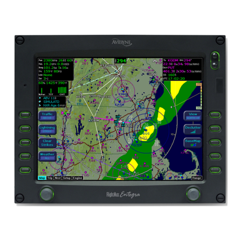
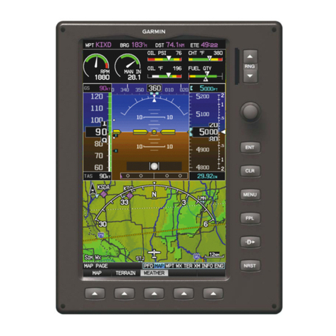
Avidyne Envision EX5000 Manual

600-00151-001 Rev 01


600-00151-001 Rev 01 -i- Envision EX5000
Document Revision History
This document is applicable to the following part numers:
lSoftware Part Number 530-00235-502 Release 8.2.2 or Later
lHardware Part Number 700-00004-()
System Configuration
All materials copyrighted including images that represent this software
Copyright 2008-2019 Avidyne Corporation. All rights reserved.
Date Revision Description
November 12, 2008 00 Released per ECO-08-426
Supports Release 8, including
TWX Cell mode and Iridium
Datalink (MLX770).
May 15, 2019 01 8.2.2 Software release.
When contacting your dealer or Avidyne technical support, and when
logging onto MyAvidyne.com for the first time, please have your
Envision EX5000 serial number and Subscriber Communicator serial
number available:
EnvisionEX5000 S/N: ________________________________
Datalink Subscriber Communicator S/N: ___________________

Envision EX5000 -ii- 600-00151-001 Rev 01
About this Guide
This guide assumes that all available sensors and software options
have been installed in your airplane. The page layouts and button
descriptions in this guide may differ slightly from what you observe on
your EX5000. If your system is configured with a partial set of the
available sensors, then some views may differ from this guide.
Note: All images contained within this document, including screenshots and
other displays, are for reference use only and are subject to change. The
images contained herein may differ slightly from your actual equipment or
display.

600-00151-001 Rev 01 -iii- Envision EX5000
Notes and Warnings
Notes and warnings provide guidance for the use of the EX5000.
Avidyne strongly suggests that you pay close attention to notes and
warnings for your own safety.
For example:
The instructions and warnings in this manual are not intended to
replace the instructions and warnings for other equipment on your
aircraft. It is critical that you as the pilot in command have a complete
understanding of the warnings, operating instructions, and limitations
for all equipment installed on your aircraft.
Note: Notes provide useful information about how to use the EX5000.
!
Warnings are prefaced with exclamation points and denote
information that can prevent serious injury or death on the
part of the user.
!
This manual assumes that the reader is an appropriately
licensed pilot. Avidyne strongly recommends that you use the
EX5000 only under VFR conditions until you are very familiar
with the EX5000.
If you have questions, please contact Avidyne at 800-284-
3963 (800-AVIDYNE) before operating with the EX5000 under
IFR conditions.
!
Before conducting flight operations, be sure to verify that time
and date settings on the System Time Setup page are correct
and in GMT (UTC). It is critical that the time be set to GMT to
provide accurate display of Datalink weather. See Section l,
"Aux Main Page" on page 67 for more information.
!
When using the EX5000, be sure to cross-check the data
displayed against other data sources for accuracy including
other flight deck instruments and charts.

Envision EX5000 -iv- 600-00151-001 Rev 01
!
The displayed terrain and obstacle indicators are only
advisory. Do not rely on the EX5000 as the sole source of
obstacle and terrain avoidance information. Always refer to
current aeronautical charts for appropriate terrain and
obstacle information.
!
The EX5000 is not intended to replace your navigation charts
or primary navigation aids. Use the EX5000 as a supplement
to other navigation sources, to enhance your overall
situational awareness. Do not rely on the navigation data in
your EX5000 as your sole reference for navigation.
!
While a properly updated database contains the latest official
information available, the manufacturers will not be held
responsible for any inaccuracy or omissions therein. Never
use the terrain displayed on the EX5000 as the only reference
for terrain avoidance.
!
The transmission of datalink weather information means there
is some delay from real time until the weather information is
displayed on the EX5000. Therefore, use datalink weather
information only for strategic route planning. Avoid severe
weather areas with a safe margin of distance. Do not use the
EX5000 to penetrate severe weather, thunderstorms, cells or
lines of cells.
!
By using Broadcast datalink, you can access weather
information made available from sources external to Avidyne
Corporation. Avidyne does not control, edit or review the
content of such information and is not responsible for such
information or the actions or conduct of any company that
provides sources of weather data through the Broadcast
datalink. Therefore, ALL WEATHER DATA ARE PROVIDED
AS-IS and neither Avidyne nor its suppliers, subcontractors,
or developers (collectively called “Suppliers”) are responsible
for: 1) the accuracy, completeness, timeliness, reliability,
content, or availability of the weather data or any other
datalink information accessed; 2) loss or damage to your
records or data; or 3) your use of, or results achieved from,
the weather data or any other information accessed.

600-00151-001 Rev 01 -v- Envision EX5000
!
Notice regarding NOTAM information
NOTAM information is subject to constant change and it is
extremely important that all pilots check with Flight Service for
applicable NOTAMs prior to EVERY flight. Call 1-800-
WXBRIEF (992-7433) for the latest information.
The NOTAM information provided by the EX5000 is for
planning purposes only. Always consult official NOTAMS for
the latest restrictions.
Avidyne does not provide a complete list of NOTAMS. Local
NOTAMS, most laser light NOTAMS, and any NOTAMS other
than restricted airspace are not listed.
By using the Avidyne Services you are able to access
information made available from a variety of sources. Avidyne
does not control, edit or review the content of such information
and is not responsible for such information or the actions or
conduct of any company that provides sources of weather
data procured by Avidyne. Therefore, although Avidyne uses
diligent efforts to provide Services of high quality, ALL
SERVICES AND WEATHER DATA ARE PROVIDED AS-IS
and neither Avidyne nor its suppliers, subcontractors,
information sources or developers (collectively called
“Suppliers”) are responsible for: 1) the accuracy,
completeness, timeliness, reliability, content, or availability of
the Services or any information accessed; 2) loss or damage
to your records or data; or 3) your use of, or results achieved
from, the Services or any information accessed.

Envision EX5000 -vi- 600-00151-001 Rev 01
This page intentionally left blank.

600-00151-001 Rev 01 -vii- Envision EX5000
Table of Contents
1 Introduction.............................................................. 1
Using the Envision EX5000 MFD ................................................ 2
Power Up..................................................................................... 4
2 Map Page .................................................................. 7
Map Page—Controls ................................................................... 8
Map Symbols—Terrain and Position ......................................... 16
Map Symbols—Runways and Flight Plan ................................. 19
Map Orientation Control ............................................................ 20
Errors Displayed on the Map Page............................................ 21
Loss of GPS Input ............................................................... 21
Loss of Heading Input ......................................................... 21
3 CMax Chart Pages (Optional) .............................. 25
Expired Charts........................................................................... 25
About CMax............................................................................... 27
About Geo-Referenced Charts .................................................. 28
CMax Chart Page ...................................................................... 28
4.2...........................................................European VFR Charts33
CMax Views............................................................................... 35
Procedure Chart Views ....................................................... 35
Airport Chart Views ............................................................. 37
CMax Selection Page ................................................................ 39
Selecting an Airport ................................................................... 41
Chart NOTAMs Page .......................................................... 43
4 Traffic Mode and the Traffic Page ....................... 47
The Dedicated Traffic Page....................................................... 47
Traffic Symbols.......................................................................... 50
TIS Sensor Status ..................................................................... 51
5 Trip Page................................................................. 53
6 Nearest Page (NRST) ............................................. 63
Nearest Page............................................................................. 63
Airport Info Page........................................................................ 65
7 Aux Page – Configuring the EX5000.................... 67
Airport Filter Setup Page ........................................................... 69
Declutter Setup Page ................................................................ 71
Data Block Edit Page................................................................. 73
System Time Page .................................................................... 75
MFD CMOS Battery Operation and Replacement..................... 77

600-00151-001 Rev 01 -viii- Envision EX5000
CMOS Battery ..................................................................... 77
Operating without a CMOS Battery..................................... 77
CMOS Battery Replacement............................................... 78
8 Datalink (Optional) ................................................. 79
Broadcast Datalink .................................................................... 80
Using Broadcast Datalink in Flight ...................................... 80
Symbols Displayed using Datalink ............................................ 82
Using Datalink without a Traffic Sensor or Radar ............... 84
Nearest Page with Datalink Weather......................................... 85
Trip Page with Datalink Weather ............................................... 86
9 Reference................................................................ 87
Updating Your Databases ......................................................... 88
Loading NavData (the Navigation Database)...................... 89
Loading CMax Chart Data................................................... 91
Activating Broadcast Datalink Accounts .................................... 93
Activating XM WX Satellite Weather................................... 93
Cleaning the EX5000 Screen ................................................... 96
Sensor Status Block Symbols ................................................... 97
Map Symbols............................................................................. 99
Line Styles ............................................................................... 101
Data Blocks .......................................................................... 103
TAWS Messages..................................................................... 105
Nav Messages......................................................................... 107
Traffic Messages ..................................................................... 109
PFD Messages ........................................................................ 112
Broadcast Datalink Messages ................................................ 113
Avionics Abbreviations ............................................................ 117
10 Using EX5000 Outside the US ............................ 119
Features Available in the US Only........................................... 119
Features Available in North America ....................................... 119
Features Specific to International Flight .................................. 119

600-00151-001 Rev 01 -ix- Envision EX5000
List of Figures
Figure 1.1 Envision EX5000 MFD ..................................................... 2
Figure 1.2 Envision EX5000 Initialization Page ................................. 4
Figure 2.1 Map Page Controls ........................................................... 8
Figure 2.2 TWXCELL Mode Display ................................................ 13
Figure 2.3 Map Symbols–Terrain and Position ................................ 16
Figure 2.4 Map Symbols—Runways and Flight Plan....................... 19
Figure 3.1 Not for Navigation Watermark on Chart display.............. 26
Figure 3.2 CMax Chart Page (Airport) ............................................. 29
Figure 3.3 CMax Chart Page (Procedure) ....................................... 31
Figure 3.4 Procedure Chart views ................................................... 36
Figure 3.5 Airport Chart Views ......................................................... 37
Figure 3.6 Airport Departure Chart (Night View) .............................. 38
Figure 3.7 CMax Selection Page ..................................................... 39
Figure 3.8 Airport Selection Page .................................................... 41
Figure 3.9 Chart NOTAMs Page ...................................................... 43
Figure 4.1 Map Page—Traffic Mode ................................................ 48
Figure 5.1 Trip Page Information ..................................................... 53
Figure 6.1 Nearest Page .................................................................. 63
Figure 6.2 Airport Information Page ................................................. 65
Figure 7.1 Aux Main Page ............................................................... 67
Figure 7.2 Airport Filter Setup Page ................................................ 69
Figure 7.3 Declutter Setup Page ..................................................... 71
Figure 7.4 Data Block Edit Page...................................................... 73
Figure 7.5 System Time Page ......................................................... 75
Figure 8.1 Broadcast Receiver Options ........................................... 80
Figure 8.2 Broadcast Datalink Weather ........................................... 82
Figure 8.3 Datalink Weather without Traffic Sensors....................... 84
Figure 8.4 Nearest Page with Broadcast Datalink ........................... 85
Figure 8.5 Trip Page with Datalink Weather .................................... 86

600-00151-001 Rev 01 -x- Envision EX5000
List of Tables
Table 2.1 Thunderstorm Activity (Cell) Colors ................................ 14
Table 2.2 Track Indicator Graphics................................................. 17
Table 2.3 Obstacle.......................................................................... 18
Table 3.1 Airport Procedure Views ................................................. 36
Table 3.2 Airport Chart Views ......................................................... 37
Table 4.1 Traffic Symbols ............................................................... 50
Table 9.1 Sensor Status Block Symbols......................................... 97
Table 9.2 Broadcast Datalink Sensor Status Block (Optional)........ 98
Table 9.3 Map Symbols – Airports.................................................. 99
Table 9.4 Map Symbols – Navigational Fixes............................... 100
Table 9.5 Map Symbols – Traffic Symbols ................................... 100
Table 9.6 Map Symbols – Other ................................................... 100
Table 9.7 Airspace and Airways Lines.......................................... 101
Table 9.8 SUA and TFR Status Lines........................................... 101
Table 9.9 AIRMET and SIGMET Boundary Lines......................... 102
Table 9.10 Data Block Information................................................ 103
Table 9.11 TAWS Messages ........................................................ 105
Table 9.12 Nav Messages ............................................................ 107
Table 9.13 Traffic Messages......................................................... 109
Table 9.14 Lightning Messages .................................................... 110
Table 9.15 PFD Messages ........................................................... 112
Table 9.16 Broadcast Datalink Messages .................................... 113
Table 9.17 Avionics Abbreviations ................................................ 117

Envision EX5000 -1- 600-00151-001 Rev 01
1 Introduction
The Envision EX5000 Multi-Function Display (MFD) provides a
moving map view of your flight plan, a broadcast datalink weather,
lightning, traffic, navigation data, obstacles, terrain, and CMax™
approach plates with an intuitive user interface. The EX5000 offers
the following standard and optional features:
lLightning information display from a WX-500 or an Avidyne TWX-
670 lightning sensor, if installed.
lFull ARINC-429 databus capability, allowing the EX5000 to
display curved flight paths, procedure turns, and holding patterns
from a compatible GPS navigator.
lTraffic information display from Avidyne TAS600 Series, L-3
Skywatch, Garmin TIS, Garmin GTX345 or any compliant ADS-B
traffic system.
lTerminal procedure chart display using the CMax™ function.
lDisplay of weather and flight restriction information when
interfaced with an external Broadcast Datalink receiver or internal
Narrowcast Datalink receiver.
lDisplay of TAWS terrain information when interfaced with an
installed EGPWS system.
Note: Consult the Flight Manual Supplement (FMS) provided with the
aircraft and/or sensors prior to operation. The FMS contains information
specific to your installation and may contain operating limitations applicable
to your aircraft configuration.

Introduction
Envision EX5000 -2- 600-00151-001 Rev 01
1.1 Using the Envision EX5000 MFD
Figure 1.1 Envision EX5000 MFD
The controls on the bezel of the Envision EX5000 are placed to allow
you quick and intuitive access to the information you need, when you
need it.
1) PhotoCell Light Sensor—Automatically compensates display
brightness for varying lighting conditions.
2) Brightness Control—Allows you to override the default display
brightness and adjust the brightness level. Press the top button to
brighten the display; press the bottom button to dim it.
3
5 6
2
1
7
4
4

Using the Envision EX5000 MFD
600-00151-001 Rev 01 -3- Envision EX5000
3) Data Port—Provides a front panel access point for loading
database updates.
4) Buttons—Used to select modes or change the display as
indicated. Buttons are active when a label appears on the screen
adjacent to the key.
5) Page Control knob—The left knob provides quick access to the
main EX5000 pages, including the Map page, Trip page, and Aux
page, as well as the main pages for any optional features. The
current page is highlighted in the page Bar on the lower left
corner of screen.
6) Selection & Range Control knob—Depending on the page you
are viewing, the right knob controls functions such as selecting
items on the page or changing the view range. The label on right
knob changes as appropriate.
7) Message Bar—The message bar keeps you informed about
critical as well as routine information from the EX5000. When
information needs to be conveyed the message bar appears next
to the bottom right button.
Note: When removing the rubber cap from the data port, pull the cap gently
from the top until it pops out. Make sure the cap is out of the way (but not
removed) before plugging anything into the USB port.
Do not tug on the tab at the bottom of the cap; this can cause the loss of the
protective cap.
Note: The message bar displays one message at a time. If more than one
message is available, the message bar will display the highest priority
message first. Press the ACK button to clear the current message and view
those underneath.

Introduction
Envision EX5000 -4- 600-00151-001 Rev 01
1.2 Power Up
On power up, the system performs a brief hardware self-test, then
initializes its functions systematically. After initialization (about a
minute after power-on), the title page, with database currency
information, is displayed. Check to ensure that you do not have any
expired databases before continuing.
When the EX5000 is ready the, “Press any bezel key to continue,”
message is displayed.
Figure 1.2 Envision EX5000 Initialization Page
The EX5000 Startup page reports the valid dates for the currently
loaded CMax¥chart data and NavData. Check to ensure that you do
not have any expired databases before continuing.
For CMax data:
lIf the issue date for the next update has passed, the Startup page
displays, “Update Available,” in white.
lIf the current date is more than a week past the issue of the next
update, the message, “Update Required,” is displayed in yellow
cautionary text.

Power Up
600-00151-001 Rev 01 -5- Envision EX5000
lIf CMax is more than 10 weeks out of date, access to the charts is
revoked until new CMax data is loaded.
For NavData, the date range is displayed if the data is valid; if it is not
valid, the word, “EXPIRED,” and the expiration data are displayed in
yellow.
For more information about updating CMax and NavData, see
Section 9.1, "Updating Your Databases" on page 88.

Introduction
Envision EX5000 -6- 600-00151-001 Rev 01
THIS PAGE INTENTIONALLY LEFT BLANK.

Envision EX5000 -7- 600-00151-001 Rev 01
2MapPage
The Map page displays your current flight plan overlaying a map of
the area over which you are flying. The EX5000 allows you to select
the data you want to display on the Map page.
Turn the Select knob on the Page Bar to Map to display the Map
page.
This section discusses the following topics:
lMap Page—Controls, page 8
lMap Symbols—Terrain and Position, page 16
lMap Symbols—Runways and Flight Plan, page 19
lMap Orientation Control, page 20
lErrors Displayed on the Map Page, page 21

Map Page
Envision EX5000 -8- 600-00151-001 Rev 01
2.1 Map Page—Controls
Buttons on the left side of the bezel provide access to sensor modes
and pages. Buttons on the right side of the bezel access the mapping
functions, and control how the Map is viewed.
Figure 2.1 Map Page Controls
1) Sensor Functions—Control overlay and modes of available
sensors. Buttons are only displayed for the sensors installed in
your aircraft:
nTraffic—Cycles through traffic sensor modes.See
Chapter 4 "Traffic Mode and the Traffic Page ,” for more
information on traffic modes.
nLightning - Controls the display of lightning strikes or cells
(cells for WX-500 only) on the map (when interfaced with an
Avidyne TWX670, an L3 WX-500 Stormscope, or a satellite-
Note: For information about the Map Symbols, see Section 9.5, "Map
Symbols" on page 99.
1
3
2
Table of contents
Other Avidyne Avionic Display manuals

Avidyne
Avidyne Entegra EX5000 User manual

Avidyne
Avidyne Entegra Manual

Avidyne
Avidyne IFD440 User manual

Avidyne
Avidyne IFD550 User manual

Avidyne
Avidyne IFD5 Series User manual

Avidyne
Avidyne Envision EXP5000 Manual

Avidyne
Avidyne Entegra EX5000 Manual

Avidyne
Avidyne IFD4 Series User manual

Avidyne
Avidyne FlightMax EX5000 Manual

Avidyne
Avidyne Entegra EXP5000 Manual