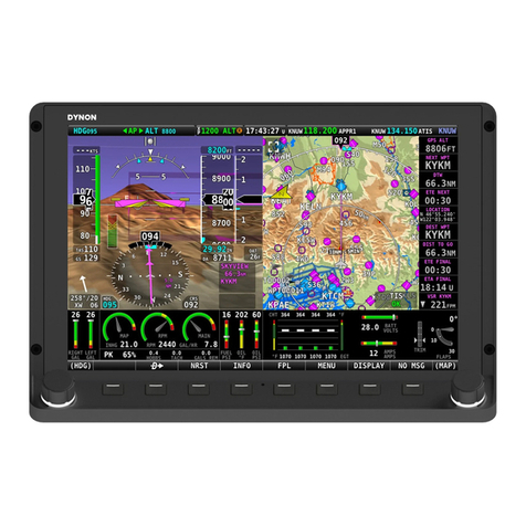
Dynon D180 FlightDEK User manual

J7886 D180 v1.1 Page 1 of 20
Dynon D180 FlightDEK Reference Manual
This manual contains information for the use of the Dynon D180
FlightDEK as configured for Jabiru 24-7886.

J7886 D180 v1.1 Page 2 of 20
Contents
1 Important Note................................................................................................................................... 3
2 Definitions ......................................................................................................................................... 3
3 Overview & Basic Operation .............................................................................................................. 4
3.1 Power ......................................................................................................................................... 4
3.2 Front Panel Layout ..................................................................................................................... 4
3.3 Screens and Pages .................................................................................................................... 4
3.4 Cycling Screens ......................................................................................................................... 5
3.5 Menus ........................................................................................................................................ 5
3.6 Menu Functionality ..................................................................................................................... 5
3.7 Menu Flows ................................................................................................................................ 6
3.8 Alerts .......................................................................................................................................... 6
3.8.1 Alarm Indicators .................................................................................................................. 6
3.8.2 SHOW PAGE ...................................................................................................................... 6
3.8.3 ALARM SILENCING ............................................................................................................ 7
3.8.4 ALARM ACKNOWLEDGE ................................................................................................... 7
3.8.5 Latching and Self-clearing Alarms ....................................................................................... 7
4 Screens ............................................................................................................................................. 8
4.1 EFIS Main Page ......................................................................................................................... 8
4.1.1 BARO – Changing Altimeter Setting .................................................................................... 9
4.2 AUX Page ................................................................................................................................ 10
4.3 EMS Page ................................................................................................................................ 10
4.4 TIMES Page ............................................................................................................................. 11
4.5 EMS FUEL Computer Page ..................................................................................................... 11
4.6 HSI Page .................................................................................................................................. 12
5 Autopilot Operation .......................................................................................................................... 13
5.1 EFIS AP Menu and Displays .................................................................................................... 13
5.1.1 EFIS AP Menu and Status ................................................................................................. 13
5.1.2 Bugs Display ..................................................................................................................... 13
5.1.3 Bugs Graphical Appearance .............................................................................................. 13
5.2 AP Modes ................................................................................................................................ 14
5.3 EFIS Autopilot Control .............................................................................................................. 14
5.3.1 Mode -(H, T, or N) ............................................................................................................. 14
5.3.2 (HDG, TRK or NAV) OFF/ON ............................................................................................ 15
5.3.3 ALT OFF/ON ..................................................................................................................... 15
5.3.4 180 .................................................................................................................................... 15
5.3.5 BUGS ................................................................................................................................ 16
5.3.6 Out of Trim Indicator .......................................................................................................... 16
5.4 AP74 Autopilot Control ............................................................................................................. 17
5.4.1 AP74 Indicators ................................................................................................................. 17


J7886 D180 v1.1 Page 3 of 20
5.4.2 AP74 Controls ................................................................................................................... 17
5.5 HSI - GPS Overlay ................................................................................................................... 19
1 Important Note
The Dynon D180 FlightDEK is an instrument that is configurable for many different aircraft and engine
types. It is also capable of managing inputs from a variety of optional sensors.
Whilst this aircraft has had the EFIS customised on installation, it is still possible for a user to actively or
inadvertently alter many of the settings. Care must be taken to avoid this. At best, another pilot may not
be able to access key information, and at worst, may result in the aircraft being inoperable until we can
engage a professional to reset the EFIS at our cost.
Please report immediately if you think that some aspect of the EFIS operation does not meet the directions
given in this guide.
2 Definitions
EFIS Electronic Flight Information System
EMS Engine Management System
HSI Horizontal Situation Indicator

J7886 D180 v1.1 Page 4 of 20
3 Overview & Basic Operation
It is essential that all pilots of 7886 are familiar with the overview and basic operation of the D180.
Operation of advanced features, and the Auto-pilot, are only required for pilots wishing to utilise these
features.
3.1 Power
The D180 will power up when the master switch is turned on. It is acceptable to have the D180 on during
engine crank.
Power On – Press button 1.
Power Off – Press and hold button 1 until the display turns off.
3.2 Front Panel Layout
The display is set up to provide all
necessary flight information.
The buttons are used to turn the
instrument on and off, cycle
between screens, scroll through
menus, and adjust instrument
parameters
3.3 Screens and Pages
Screens contain one or two pages and pages
contain groups of similar information.
A page is a section of the screen that contains
a collection of related data. Pages share the
screen with other pages (2/3, 1/3 split).

J7886 D180 v1.1 Page 5 of 20
3.4 Cycling Screens
Buttons 1 and 6 cycle to the
previous and next screens,
respectively.
3.5 Menus
On a screen where no menu is already present,
buttons two through five are used to display a
menu.
All of the default screens are divided into two
pages with the left page occupying 2/3 of the
screen and the right page occupying 1/3 of the
screen.
Pressing buttons two, three, or four (all below the
left 2/3 of the screen) displays the main menu for
the left page and pressing button five (below the
right 1/3 of the screen) displays the main menu
for the right page.
3.6 Menu Functionality
A menu consists of two rows of gray boxes
containing text. The upper row contains one
tab that denotes the currently displayed
menu. The lower row contains six labels that
denote the function of the button below it.
Many of the onscreen elements move up to
avoid the menu. This prevents the menu
from obscuring useful data while it is up.
Upon exiting the menu, the screen returns to
its normal appearance.
Pressing a button either displays another
menu or adjusts a parameter. If there is no
text above a button, then that button does
not have a function in the context of that
menu. Occasionally, a button label spans

J7886 D180 v1.1 Page 6 of 20
two or more buttons. In this case, any button
below the label invokes the command.
If a menu contains more options than there
are buttons, the MORE label is displayed
over button five. Pressing this button shows
you the next set of options in the current
menu.
In any menu, press the BACK button to
return to the previous menu and save any
changes. In all top-level menus, button six is
the EXIT button. Pressing EXIT removes the
menu system and moves many of the
onscreen elements down to their original
positions.
3.7 Menu Flows
Each page has its own main menu, which
may contain options for navigating to other
menus or choosing and adjusting
parameters.
For example, the EFIS Main Page menu
contains an EFIS menu tab and button
labels for MENU►, BARO, AP, LISTS,
MORE, and EXIT.
Pressing MORE reveals the rest of the EFIS
menu. This menu contains options for
SETUP, INFO, DIM, TIMER, MORE, and
EXIT. Pressing MORE on this menu simply
returns you to the first part of the EFIS
menu.
3.8 Alerts
3.8.1 Alarm Indicators
Any time a built-in or preconfigured alarm set point is exceeded, you are alerted via visible alarms.
When an alarm is triggered, the following things occur:
The measurement’s value and tick color are highlighted red
The measurement’s value and tick blink
A red alarm bar appears at the bottom of the screen with a message identifying the out of range
measurement
Below the alarm bar, the alarm menu gives you options for what to do next. See the following
subsections for more information
NOTE:
No audio alert output is fitted to this aircraft so you will not hear an audible alarm.
3.8.2 SHOW PAGE
If the alarming measurement is not displayed on your current screen, or is available on a page which
displays it better, a SHOW [PAGE] button is included in the alarm menu. [PAGE] is replaced with the
name of the actual page that is displayed when you press the button. Press this button to display the
page where the alarming measurement is best displayed. From there, you may press GO BACK to

J7886 D180 v1.1 Page 7 of 20
return to your original screen, leaving the alarm indications active, or press ACK to remove the alarm
and return to your original screen.
3.8.3 ALARM SILENCING
As this aircraft is not fitted with an audible alarm, pressing the SILNCE button has no function.
3.8.4 ALARM ACKNOWLEDGE
To acknowledge the alarm, press the ACK button. The ACK button has a number next to it indicating the
number of currently posted alarms. If this number is higher than 1, after you press ACK the alarm text for
the next posted alarm is displayed in the alarm bar. Pressing ACK does the following:
Removes the alarm bar and alarm menu (if no other alarms are stacked up), and brings up the
previous menu.
Stops the blinking of the relevant display
Returns the display to the screen configuration displayed before the alarm occurred (if you
pressed SHOW [PAGE])
The tic and numeric value remain red until the condition no longer exists. The alarm automatically
rearms whenever the alarm condition is removed.
3.8.5 Latching and Self-clearing Alarms
Alarms may be set to be latching, while others may be self-clearing.
LATCHING ALARMS
If an alarm occurs on a sensor that is latching, the alert displays on screen until the ACK button is
pressed, even if the alarm condition goes away. This means if, for example, your oil pressure
momentarily gets too high but returns to normal, the instrument continues to alarm on the condition until
that alarm is acknowledged. Latching alarms let you to know if an alarm happened momentarily, when
you might have otherwise missed it.
SELF-CLEARING ALARMS
If an alarm occurs on a sensor configured to be self-clearing, the alert displays on screen until either the
ACK button is pressed or the alarm condition goes away. Consider the example where a fuel pressure
alarm to be isself-clearing. If the engine’s fuel pressure momentarily rises too high but then returns to
normal, the D180 alarms for that brief instant, but stops as soon as the alarming condition has ceased;
no acknowledgement is needed.

J7886 D180 v1.1 Page 8 of 20
4 Screens
The screens available in rotation are:
1. EFIS / EMS (boot-up screen)
2. EFIS / AUX
3. EFIS / FUEL
4. EFIS / TIMES
5. EFIS / HSI
4.1 EFIS Main Page
The EFIS screen contains the following:
Horizon line, pitch and roll indicators
(brown/blue at centre of screen)
Heading tape, digital readout and
turn rate indicator (top)
Altitude tape, digital readout, and VSI
(right)
Airspeed tape, digital readout, and
trend (left)
Bugs
Slip/skid ball
Clock (Z indicates Zulu time)
Autopilot Status Indicator
Altimeter barometer setting (bottom
right)
4.1.1 EFIS Voltmeter
The voltmeter displays 3 rows of information
corresponding to the three power inputs:
M – Master switch voltage
E – External backup voltage
I – Internal battery voltage
An alert will be displayed when the iinternal
battery is low.

J7886 D180 v1.1 Page 9 of 20
4.1.2 BARO – Changing Altimeter Setting
Set the primary altimeter to the correct
altitude (eg 110ft at YREN).
Take the pressure reading from the
altimeter.
Select the EFIS BARO option
When the BARO menu is displayed, the
value-setting box shows the current
altimeter setting. The DEC- and INC+
buttons change the altimeter setting by 1
mbar.
Press BACK and then EXIT to exit the EFIS
menu.
The atmospheric pressure reading is
displayed in the lower right of the screen.
NOTE:
The altimeter reading may take a little time
to stabilise after being adjusted.

J7886 D180 v1.1 Page 10 of 20
4.2 AUX Page
This page displays
Voltmeter
Fuel flow
Outside air temperature (OAT)
Timers
Fuel remaining
4.3 EMS Page
This page displays
RPM
oil temperature
oil pressure
cylinder head temperature (CHT)
fuel level
fuel flow

J7886 D180 v1.1 Page 11 of 20
4.4 TIMES Page
The Times Page is divided into three sections:
TIME, TIMERS, and ENGINE TIMERS.
The Flight Timer shows the total amount of time
that oil pressure is above 15 PSI since the D180
was turned on; it does not reset until the next time
the D180 is power-cycled and oil pressure
reaches 15 PSI.
The Trip Timer shows cumulative flight time since
a manual reset. The third line of this section
contains the general purpose Timer which can be
used for a variety of functions including a tank
timer.
The Tach Timer keeps track of engine time
(normalized to cruise RPM). The Hobbs Timer
records the duration of time engine oil pressure is
at 15 PSI or higher.
NOTE:
The Hobbs Timer reading is to be noted in the
flight log as a record of engine operation time.
4.5 EMS FUEL Computer Page
This page displays fuel tank levels, fuel flow, fuel
pressure, fuel remaining, fuel used, and time
remaining.
NOTE:
Operation of the fuel computer is not
recommended for basic flight operations.
Even for advanced operations, due to the
accuracy of Jabiru fuel gauges, the fuel computer
should not be used unless the tanks are full at the
beginning of calculations.

J7886 D180 v1.1 Page 12 of 20
4.6 HSI Page
This page displays the GPS local magnetic
heading.

J7886 D180 v1.1 Page 13 of 20
5 Autopilot Operation
This section guides you through the indicators and operation of D180’s EFIS-based Autopilot (AP) and
AP74 Control Panel systems.
NOTE:
The J230 is very light and the AP servos are very responsive. The AP should be disengaged in
anything more than occasional light turbulence otherwise damage to the servos may occur.
5.1 EFIS AP Menu and Displays
AP information is displayed on the EFIS page.
5.1.1 EFIS AP Menu and Status
The AP status is displayed in the lower left of the
EFIS page. The left indicator displays the state of
the roll servo, and the right indicator displays the
state of the pitch servo.
The AP menu is available on the EFIS main
menu.
The BUGS menu is available under the AP menu.
5.1.2 Bugs Display
Whenever either the heading or altitude Bug is
toggled ON, its current value is displayed in the
lower right corner of the EFIS page.
In the example image, the heading bug is toggled
ON (i.e., displayed on the heading tape), but the
AP HDG mode is currently disengaged. The ALT
bug is set to 2250ft and the AP is currently
engaged.
5.1.3 Bugs Graphical Appearance
When the AP is not engaged for a given axis, the
respective BUG is hollow.
When the AP is engaged, the respective BUG
solid or filled in.

J7886 D180 v1.1 Page 14 of 20
5.2 AP Modes
HDG: HEADING MODE – ROLL SERVO In Heading Mode, the AP uses the roll servo to
control the aircraft’s magnetic heading.
You may adjust the heading bug to direct the
aircraft to a new target heading with the AP
engaged.
NOTE: The magnetic heading is affected by wind.
TRK: GROUND TRACK MODE – ROLL SERVO In Track Mode, the AP uses the roll servo to
control the aircraft’s GPS ground track.
You may adjust the heading bug to direct the
aircraft to a new target track with the AP engaged.
180: 180º TURN MODE – ROLL AND PITCH
SERVOS
This mode initiates a quick turnaround. The AP
enagages both servos to hold altitude in a left turn
until the aircraft is flying in the opposite direction,
and then remains in TRK and ALT hold modes.
NAV: GPS NAVIGATION MODE – ROLL SERVO To use the GPS-based NAV mode, the GPS must
have an active waypoint. When engaged, the AP
takes instruction from the GPS unit’s horizontal
navigation information.
ALT: ALTITUDE MODE – PITCH SERVO In Altitude Mode, the AP uses the pitch servo to
control the aircraft’s altitude.
You may adjust the altitude bug to direct the
aircraft to a new target altitude with the AP
engaged.
NOTE:
Input to engine power management is required to
climb or descend the aircraft within normal
operating
airspeed
s
.
5.3 EFIS Autopilot Control
This section describes the various AP
control functions available via the EFIS >
AP menu.
The AP menu includes the buttons
shown:
5.3.1 Mode -(H, T, or N)
The MODE button is followed by the
currently active lateral mode: H (HDG), T
(TRK), or N(NAV).
Pressing this button brings up another
menu where you can select the armed AP
mode. As soon asyou select a mode, the
AP menu is immediately displayed again.

J7886 D180 v1.1 Page 15 of 20
5.3.2 (HDG, TRK or NAV) OFF/ON
This button toggles the roll servo ON and
OFF in the specified mode.
NOTE:
When the AP is engaged in HDG or TRK
mode, the heading bug is synchronized to
the current heading or ground track,
respectively. The heading or track bug is
then adjusted while the AP is engaged.
5.3.3 ALT OFF/ON
This button toggles the pitch servo ON
and OFF.
NOTE:
When the AP is engaged in ALT mode,
the ALT bug is synchronized to the
current altitude. The altitude bug is then
adjusted while the AP is engaged.
5.3.4 180
This button sets a TRK bug 180° from the
current ground track.
The AP enagages both servos to hold
altitude in a left turn until the aircraft is
flying in the opposite direction. While in
the 180 mode, the 180 button is
highlightes and the AP status indicator
displays 180 in the roll axis position.
Once the turn manouvre has been
completed, the AP remains in TRK and
ALT hold modes.

J7886 D180 v1.1 Page 16 of 20
5.3.5 BUGS
You can set a marker or BUG to appear
on any or all of the three tapes.
Choose the type of bug to configure:
HDG/TRK (heading/track), IAS (Indicated
airspeed).
Heading / Track
TOGGLE: Turns the heading or track
bug on and off on the heading tape.
SYNC: Synchronises the bug to the
current heading or track.
SEL►: Selects which digit to change.
DEC-: Decreases selected digit.
INC+: Increases selected digit.
AP74 VALUE: When in the heading or
track menus, rotation of the VALUE knob
will rapidly alter the setting.
Airspeed NOTE:
A bug may be set for the airspeed but
can not be controlled through the
autopilot.
Altitude
TOGGLE: Turns the altitude bug on and
off on the altitude tape.
SYNC: Synchronises the bug to the
current altitude.
SEL►: Selects which digit to change.
DEC-: Decreases selected digit.
INC+: Increases selected digit.
AP74 VALUE:The altitude bug can be
adjusted at any time using the VALUE
knob.
5.3.6 Out of Trim Indicator
When the Autopilot is flying the aircraft in
Altitude Mode, an out-of-trim indicator
can appear to the right of the AP Status
Indicator. This alerts you when there is
excessive load on the pitch servo. The
indicator instructs you in the direction to
trim the nose to reduce elevator load.

J7886 D180 v1.1 Page 17 of 20
5.4 AP74 Autopilot Control
The AP74 has all the functionality of the EFIS > AP menu while providing an alternate way to interpret
and use the Autopilot.
5.4.1 AP74 Indicators
The AP74 red button indicator lights have the
following meanings:
AP ON when any servo is active.
HDG ON when the roll servo is armed or active
in the heading mode.
TRK ON when the roll servo is armed or active
in the ground track mode.
NAV ON when the roll servo is armed or active
in the GPS navigation mode.
ALT ON when the pitch servo is armed or
active in the altitude mode.
5.4.2 AP74 Controls
AP Button When its indicator is off, pressing the AP button engages the AP in the pre-armed
mode(s).
When the AP button’s indicator is on, pressing the AP button disengages all axes of
the AP, but leaves the last-used modes armed.
If you push and hold the AP button for 2 seconds, the AP engages in 180 Mode.
NOTE:
The HDG/TRK and ALT bugs are synchronized to the heading/track and altitude
values each time the AP is engaged.
VALUE Knob When no menus are displayed, the VALUE knob changes the HDG/TRK bug, ALT
bug or BARO setting. Press the VALUE knob to cycle between modes.
When in any EFIS menu which adjusts a numerical value, turning the VALUE knob
adjusts the selected parameter.
Pressing the VALUE knob when in any menu exits the menu system completely.
Pushing and holding the knob while changing a bug synchronizes the bug to the
current value.
HDG Button When its indicator is off, pressing the HDG button arms the roll servo in Heading
Mode and turns on the indicator.
When its indicator is on, pressing the button disarms/deactivates the roll servo and
turns off the button’s indicator.
TRK Button When its indicator is off, pressing the TRK button arms the roll servo in Track Mode
and turns on the indicator.

J7886 D180 v1.1 Page 18 of 20
When its indicator is on, pressing the button disarms/deactivates the roll servo and
turns off the button’s indicator.
NAV Button When its indicator is off, pressing the NAV button arms the roll servo in Navigation
Mode and turns on the indicator.
When its indicator is on, pressing the button disarms/deactivates the roll servo and
turns off the button’s indicator.
ALT Button When its indicator is off, pressing the ALT button arms the pitch servo in Altitude
Mode and turns on the indicator.
When its indicator is on, pressing the button disarms/deactivates the pitch servo and
turns off the button’s indicator.

J7886 D180 v1.1 Page 19 of 20
5.5 HSI - GPS Overlay
The HSI will overlay GPS information while the GPS has an active flight plan between two points.
Text displays. In this area a variety of
information is displayed in text format. Displayed
here is the ground track (TRK), the course (CRS),
ground speed (SPD), distance to next waypoint
(DTW), and up to two bearing pointer selections.
Course indicator. The course indicator points in
the direction of the course that the GPS is
reporting. In a situation with no winds, keeping the
course indicator pointed straight up and in line
with the heading pointer keeps the aircraft on
course. This indicator is fixed to the rotation of the
DG, so it is easy to see which way you must turn
to get on course.
To indicator. This arrow always points the same
way as the course line, as indicated in the small
oval.
Course Deviation Indicator (CDI). The CDI
indicates how far to the left or right of your
selected ground course you are (CDI in large
oval).
Depending on the scale that you are in, each dot
indicates 0.06 n.m. (Approach), 0.2 n.m.
(Terminal), or 1.0 n.m. (Enroute). When on
course, the course indicator and the CDI make a
solid line, making it easy to see when there is little
error in your aircraft’s position. Unlike a CDI
indicator found in basic aircraft, the CDI needle on
an HSI rotates with the DG and course indicator.
By turning the aircraft towards the CDI needle so
the CDI needle is on top of the course line you
reduce your deviation.
Track indicator. This indicates your direction
over the ground as reported by the GPS. This is
different than your magnetic heading when there
are crosswinds present. Since this is your actual
ground track, keeping this directly above your
course pointer (when the CDI is centered) keeps
you on course, even if your magnetic heading is
different.
Scale indicator. This shows you what scale the
CDI is using. Since serial GPS streams do not
indicate the correct scaling mode, this must be
configured manually with the “scale” button under
the HSI menu.
The three options are “E” for enroute (5 n.m. full
scale), “T” for terminal (1 n.m. full scale),
anapproach (0.3 n.m. full scale). The current
scale name and full scale range is indicated on
the sreen.

BARO – Changing Altimeter Setting
Set the primary altimeter to the correct altitude (eg 110ft at YREN).
Take the pressure reading from the altimeter.
Press button 2 to open the EFIS menu
Select the EFIS BARO option.
Adjust using DEC- and INC+ buttons.
Press BACK and then EXIT to exit the EFIS menu.
The altimeter pressure reading is displayed in the lower right of the
screen.
Flight Log – Time
Change the screen to show the TIMES page.
Record HOBBS timer reading.
AP – Quick Reference
Ground Track – eg using Oz Runways
Arm the TRK and ALT on the AP74
Engage AP
TRK and ALT are synchronised to current
Adjust TRK using the VALUE knob or EFIS > AP > BUGS
Adjust ALT using the AP74 VALUE knob (press to cycle) or
EFIS > AP > BUGS
NAV – using GPS
Arm the NAV and ALT on the AP74
Engage AP
ALT is synchronised to current. NAV is set to GPS track.
Adjust ALT using the AP74 VALUE knob (press to cycle) or
EFIS > AP > BUGS
Table of contents
Other Dynon Avionic Display manuals

Dynon
Dynon SkyView Classic User manual

Dynon
Dynon D2 Pocket Panel Manual

Dynon
Dynon SkyView HDX System User guide

Dynon
Dynon EFIS-D10A User manual

Dynon
Dynon D3 Manual

Dynon
Dynon SkyView HDX System Technical Document

Dynon
Dynon SkyView SE User manual

Dynon
Dynon SkyView Classic User manual

Dynon
Dynon SkyView HDX System Technical specifications

Dynon
Dynon SkyView HDX System Instruction sheet