LA Audio MS1224 User manual

Active Mic
Splitter
Operation Manual
August ‘04

Page 2
This page has been left intentionally blank for your notes

Page 3
CONTENTS
1.0 OVERVIEW 4
2.0 TECHNICAL SPECIFICATION 5
3.0 INSTALLATION 6-7
3.1 Inspection and unpacking
3.2 Operating Environment
3.3 CE Standard and LVD
3.4 Power Requirement
3.5 Warranty
4.0 DESCRIPTION OF CONTROLS 8
4.1 Phantom
4.2 +48V indicator
4.3 Pad
4.4 Listen
5.0 EXTERNAL CONNECTIONS 9-14
5.1 Input
5.2 Link
5.3 Output A, B, C and D
5.4 Power In
5.5 Power Out
5.6 Signal Levels
5.7 Multiway Connector Option
5.8 Input-Output Options
5.9 Grounding Output D
6.0 POWER SUPPLY UNIT 15-17
6.1 Description of Front Panel
6.2 External Connections
6.3 Power Requirements
7.0 DIMENSIONS 18

Page 4
1.0 OVERVIEW
PRODUCT OVERVIEW
Main Features:
• 12 Channel 1 into 4 (12 into 48) Active Mic Splitter
• Unique Input & Output configuration options
• Unity Gain signal path for ease of set-up
• Drives long cable runs without level loss
• Compact design e.g. a 48 channel System in 13U (including Power Supply)
• Channel Monitoring facility
• Individual Input and Output group earth lift switches
The MS1224 is a 12 channel, 1 into 4 Unity Gain Active Microphone Splitter designed for
applications where multiple feeds are required from one set of microphones without the
signal degradation experienced with passive splitting solutions. The Unity Gain design
principle combined with excellent line driving ability ensures that unity levels are delivered
at the end of each feed, even over considerable distance, thereby saving time in
recalibrating levels.
Each of the MS1224's channels has four independently buffered, transformer balanced
outputs and a fifth dedicated parallel Link output. The Link output may be used to provide
a direct, non active feed, for instance to the FOH console, or it can be used to daisy chain
adjacent channels to provide more output feeds from a single microphone, for instance
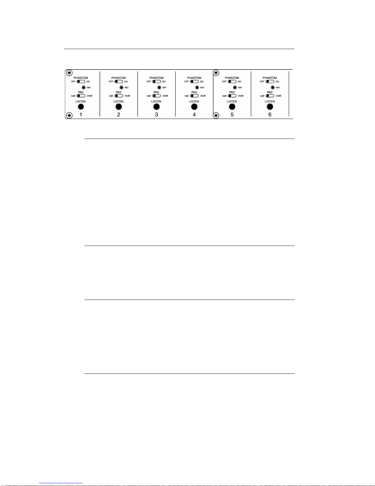
for Press Box applications. The inputs are electronically balanced with a Pad switch for
connection of line level signals. Switchable Phantom Power is provided with a Phantom
Presence LED.
The MS1224 incorporates a channel monitoring circuit, which is accessed on the PSU
unit. Each channel has a Listen button that connects it momentarily both to an LED
bargraph and headphone socket on the PSU front panel. The headphone monitor circuit
incorporates a dynamics enhancement and protection system. This controls the dynamics
of the signal in a way that amplifies very low background levels whilst limiting high signal
levels. This enables monitoring of microphone function during set up without the need of
a vocalist being present on the mic. It also provides user protection against sudden loud
signals.
A unique design feature of the MS1224 is the option to configure the way that Input and
Output connectors are presented on the front and rear of the unit. As each customer has
their own views on this we have given the flexibility of presenting the Input and two
Outputs on the front and three Outputs on the rear, or vice-versa. In addition the Output
designated as Link can be positioned either below the Input connector, or above the
group of three Outputs. Thereby giving four possible permutations. The required
configuration can be specified ex-works or simply reconfigured at a later stage.
Each XLR connector on each channel is equipped with 3 pin molex connectors for wiring
to a multicore set. A standard rear panel multicore plate is available for use with 56 way
EDAC connectors. Thereby all connectors per channel can be accessed via a multicore
cable.

Page 5
2.0 TECHNICAL SPECIFICATIONS
2.1 MS1224 ACTIVE MIC SPLITTER
ELECTRICAL
Frequency Response: 20Hz to 20kHz, +0, -0.5dB
Equivalent Input Noise: -122dBu, 20Hz to 20kHz
THD + Noise: < 0.01%
Input Impedance: 2k
Maximum Input Level: 0dBu (+20dBU with Pad)
Output Impedance: < 15R
Load Impedance: > 150R
Gain: 0dB (-20dB with Pad)
Bargraph Calibration: -60dB to +20dB
Power Requirement: +17V, -17V DC and +48V
PHYSICAL
Input Connector: XLR 3 pin female (Pin 2 = hot)
Output Connector: XLR 3 pin male (pin 2 = hot)
Interconnection: 36 way Centronics cable
Multiway connector option: 56 pin EDAC
Dimensions mm (ins): 483 (19") W
225 (8.85") D
133 (5.25") H (3U)
Weight: Unit 5.5kg (12.1lbs)
Shipping 6.1kg (13.4lbs)
Temperature Range: Operating 0°C to 50°C
Storage -30°C to +75°C
2.2 MS1224 POWER SUPPLY
Power connector: Detachable lead IEC
Dimensions: 483 (19") W
225 (8.85") D
44 (1.75") H (1U)
Weight: Unit 3.5kg (7.7lbs)
Shipping 4.1kg (9.02lbs)
Power requirement: 85VA, 115/230V AC, 50/60Hz

Page 6
3.0 INSTALLATION
3.1 INSPECTION AND UNPACKING
The MS1224 Active Mic Splitter and Power Supply units have been carefully
packed at our factory in a carton designed to withstand handling in transit. Should
the unit appear to have been damaged in transit, notify your dealer immediately
and do not discard any of the packing. The carton should contain -
• The MS1224 Active Mic Splitter or MS1224 Power Supply unit
• Power cord
• 36 way Centronics cable (not with the Power Supply)
• Operator Manual (this book)
3.2 OPERATING ENVIRONMENT
The MS1224 Active Mic Splitter and Power Supply units are designed to operate
between 0°C and 40°C (32-112°F) with relative humidity no more than 80%.
Should the units be installed in an equipment rack, ensure that the ambient
temperature conforms to these levels.
3.3 CE STANDARDS AND THE LOW VOLTAGE DIRECTIVE (LVD)
The MS1224 Active Mic Splitter and Power Supply units have been designed to
comply with the latest Electromagnetic Compatibility (EMC) regulations. However
we recommend you do not operate the unit close to strong emitters of
electromagnetic radiation such as power transformers, motors, mobile telephones
or radio transmitters.
The unit should only be connected to a power supply of the type described in 3.4
POWER REQUIREMENTS or as marked on the unit. Disconnect the mains
supply before removing any cover.
See Section 6.3, concerning power requirements for the MS1224 Power Supply.
3.4 POWER REQUIREMENTS
The MS1224 Active Mic Splitter is designed to work from low voltage DC supplies
only. The MS1224 Power Supply provides Phantom power (+48V) and Audio
supplies of +17V and -17V - see Section 6.0.
3.5 WARRANTY
Your LA Audio MS1224 Active Mic Splitter and Power Supply units have been
manufactured to a high standard using quality components. If correctly installed
and operated the unit should give years of problem free operation.
However in the event of a defect in material or workmanship causing failure of the
unit within 1 year of the date of original purchase we will agree to repair, or at our

Page 7
discretion replace, any defective item without charge for labour or parts. To
receive service under this warranty it is necessary to return the unit to an LA
Audio authorised service centre or to the factory with a dated receipt as proof of
purchase. After repair the unit will be returned to you free of charge.
Limitations:
This warranty does not cover damage resulting from accident or misuse. The
warranty is void unless repairs are carried out by an authorised service centre.
The warranty is void if the unit has been modified other than at the manufacturers
instruction. The warranty does not cover components which have a limited life,
and which are expected to be periodically replaced for optimal performance. We
do not warrant that the unit shall operate in any way other than as described in
this manual.

Page 8
4.0 DESCRIPTION OF CONTROLS
4.1 PHANTOM switch
Individual Phantom Power switches per channel switch +48V on to the Input
connector.
Please note:
To prevent the chance of damage to any external pieces of equipment, do not
use the +48V power option with unbalanced input sources i.e. those where pins
1&3 or 1&2 are connected together.
To avoid loud and potentially damaging electrical noise always turn down all
associated amplifiers and always connect microphones before switching phantom
power on.
4.2 +48V led
This led lights whenever a voltage i.e. phantom power is present at the Input
connector. The Phantom Power source detected can be either internal (via
MS1224 Power Supply) or external (via for example a FOH console).
4.3 PAD switch
This switch inserts a 20dB pad into the signal path. To be used when line level
signals are connected to the MS1224.
Please note:
Maximum input level with the PAD in the 0dB position is 0dBu (0.775V rms) and
with the PAD in the 20dB position it is +20dBu (7.75V rms)
4.4 LISTEN switch
This momentary action push switch connects the channel's signal onto the
monitor bus. The monitoring section is housed in the Power Supply unit - see
Section 6.1 and provides both a visual indication of signal level and headphone
monitoring.

Page 9
5.0 EXTERNAL CONNECTIONS
Option A - Front view Option A - Rear view
5.1 INPUT
The Microphone input is electronically balanced via a XLR-F connector with pin 2
wired hot (signal +). Input impedance is 2k and is suitable for low impedance
dynamic or capacitor microphones.
Although the inputs are designed for balanced operation either pin 2 or pin 3 can
be connected via the external cable to pin 1 for unbalanced operation.
Pin 1 on the Microphone XLR is grounded via the INPUTS Ground Lift switch on
the power supply - see Section 6.1.
5.2 LINK
LINK is wired in parallel with the INPUT connector and can be used to provide a
direct feed from the source.
Ex-works the LINK connector is fitted on the front of unit (Option A). It can
however be swapped for OUTPUT A which is normally mounted on the rear
panel (Option C) - see Section 5.6.
5.3 OUTPUT A, B, C and D
All outputs on the MS1224 are transformer balanced on 2 pin XLR-M connectors
with pin 2 wired hot (signal +).
Either pin 2 or pin 3 can be connected to pin 1 via the external cable to provide
an unbalanced feed.
Pin 1 on OUTPUT A, B and C are connected to ground via the associated
Ground Lift switches on the Power Supply unit - see Section 6.1.

Page 10
Pin 1 on OUTPUT D is normally supplied with pin 1 ground lifted. Refer to Section
5.9 for details of how to ground OUTPUT D.
5.4 POWER IN
A 36 way Centronics style connector carries all DC power, signal monitoring and
grounding connections.
Normally connected to the MS1224 Power Supply Unit - see Section 6.0.
5.5 POWER OUT
A duplicate power connector to allow easy daisy chaining of multiple MS1224
Active Mic Splitters to a common power supply.
5.6 SIGNAL LEVELS
The Input to Output gain on the MS1224 is 0dB i.e. unity. Maximum input signal
level will depend on the setting of the PAD switch.
The 0dB position (switch up) is for microphone levels and maximum input level is
0dBu i.e. 0.775Vrms. The -20dB position should be used for line level signals.
Maximum input level is then +20dBu and overall voltage gain will be -20dB.
Maximum Output level from the MS1224 is +20dBu into a 600R load.
5.7 MULTIWAY CONNECTOR OPTION
In the standard ex-works configuration the connector panel on the MS1224 Active
Mic Splitter has no provision for multiway connectors. However an optional
connector panel is available with cut outs for up to three 56way EDAC style
connectors - see following diagram.
Connections to the multicore connectors depend on which option is used. The
following is a list of available connectors on each of the channel cards -
Option A and B: Option C and D:
INPUT P1 INPUT P1
OUT A P7 OUT A LK4
OUT B P9 OUT B P9
OUT C P10 OUT C P10
OUT D P8 OUT D P8
LINK P3 LINK LK2

Page 11
The following diagram shows two wiring examples when using 56 way EDAC
connectors.
5.8 INPUT-LINK-OUTPUT OPTIONS A, B, C and D
A unique feature of the MS1224 is the ability to re-configure the Input-Output
panels -
Option A: INPUT, LINK and OUTPUT D are on the front of unit and
OUTPUT A, B and C are on the rear of unit
Option B: The reverse of Option A i.e. INPUT, LINK and OUT D are on rear
of unit and OUT A, B, C are on front of unit.
Option C: INPUT, OUT A and OUT D are on front of unit and LINK, OUT B
and OUT C are on rear of the unit.
Option D: The reverse of Option C i.e. INPUT, OUT A and OUT C are on
rear of unit and LINK, OUT B and OUT C are on front of unit.
The standard factory configuration is Option A. The following procedure explains
how to change this to Option B, C or D -

Page 12
Coverting from option A to Option B:
• Remove the top cover – 8 x M3 countersunk screws.
• Remove chassis – 8 x Hex Button screws (2mm AF Allen Key required) and
4 x M3 x 6 countersunk screws on base.
• Disconnect the 10 way ribbon cable connector from each of the channel
boards (J4).
• Disconnect the 4 way power cable from the rear of the Centronics connector
panel.
• Disconnect 20 way ribbon cable from Centronics panel.
• Remove the Switch panel assembly – 8 x M3 Pan screws.
• Remove the Connector panel assembly – 8 x M3 Pan screws.
• Turn chassis through 180° i.e. 10 way ribbon cable connectors (J4) on
channel boards are now closer to the rear of the unit, refit the main assembly
to the chassis – 8 x M3 Hex, Button head screws (2mm Allen Key required)
and 4 x M3 x 6 countersunk screws on base.
• Re-fit Switch panel assembly to front of unit – 8 x M3 Pan screws and plug in
12 x Ribbon cable connectors.
• Re-fit Connector panel assembly to rear of unit – 8 x M3 Pan screws and
plug in the 20 way ribbon cable.
• Re-connect 4 way power cable to rear of Switch panel.
• Re-fit cover – 8 x M3 countersunk screws.
Channel board link positions for Option A and B
Converting from Option A to Option C:
Follow the above procedure but before re-assembling make the following
changes to the Channel boards -

Page 13
Option C - front view Option C - rear view
• Referring to the Channel board diagram –
• Remove the 3 x jumper links fitted to LK1 and LK2
• Remove the 3 x jumper links fitted to LK3 and LK4
Channel board link positions for Option C and D
• Fit a 3 way, 16cm cable assembly (Order No. 2010205) between P3 & P6
• Fit a 3 way, 16cm cable assembly (Order No. 2010205) between P2 & P7
• Turn chassis through 180° (only required for Option D) i.e. 10 way ribbon
cable connectors (J4) on channel boards are now closer to the rear of the
unit, refit the main assembly – 8 x M3 Hex, Button head screws (2mm Allen
Key required).
• Re-fit Switch panel assembly – 8 x M3 Pan screws and plug in 12 x Ribbon
cable connectors.
• Re-fit Connector panel assembly – 8 x M3 Pan screws and plug in the 20
way ribbon cable.

Page 14
• Re-connect 4 way power cable to rear of Switch panel.
• Re-fit cover – 8 x M3 countersunk screws.
5.9 GROUNDING OUTPUT D
Referring to the above diagram the shorting link on P11 can be used to ground pin
1 on OUT D.
Please note:
Ex-works default is with OUTPUT D ground lifted.

Page 15
6.0 POWER SUPPLY UNIT
The MS1224 Power Supply unit houses the INPUT and OUTPUT ground lift
switches, DC power supplies and monitoring section. Each Power Supply can
power up to four MS1224 Mic Splitter racks i.e. 48 channels.
6.1 DESCRIPTION OF FRONT PANEL
INPUTS
Ground lift switch and fuse, common to all INPUTs.
OUTPUT A, B and C
Ground lift switches and fuses for OUTPUT A, B and C respectively.
Please note:
Pin 1 on OUTPUT D is normally supplied with ground lifted. See Section D doe
details on grounding OUTPUT D . This should be repeated on all channel boards
that are required to be grounded.
The front panel accessible fuses are connected in series with the Ground Lift
switches and provide over-current protection should voltage potentials occur
between interconnect equipment.
To ensure continued protection always replace the ground lift fuses with a
similar type and rating i.e. 20mm, 1A fast blow.
DC SUPPLIES
The three leds are associated with the Phantom Power (+48V) and Audio (-17V
and +17V) supplies. In normal operation all three should be lit.

Page 16
MONITOR METER
A 10 segment bargraph which displays the level of the signal on the monitor bus.
The display has a very wide input range, -60dBu to +20dBu, so can be used to
give an indication of signal presence as well as signal level.
LEVEL
Controls the volume of the monitor signal to the PHONES output socket
Please note:
The channel monitoring circuit on the MS1224 incorporates a dynamics
enhancement and protection system. This controls the dynamics of the signal in a
way that amplifies very low background levels whilst limiting high signal levels.
This enables monitoring of microphone function during set up without the need of
a vocalist being present on the mic. It also provides user protection against
sudden loud signals.
PHONES
Headphone output of the monitor buss signal.
Please note:
The headphone output uses a standard 6.35mm TRS socket with the monitor
signal fed to both Tip and Ring connections i.e. suitable for use with standard
stereo headphones.
POWER
Mains power on-off switch with led indicator.
6.2 EXTERNAL CONNECTIONS
POWER OUT
36 way Centronics style connector for connecting to MS1224 Mic Splitter units.
Please note:
If using cables other than those supplied with the MS1224 Active Mic Splitter
ensure that all pins are connected and that it is wired pin 1 to pin 1 etc.

Page 17
MAINS
Standard IEC type detachable mains cable connector.
FUSE
Standard 20mm fuse connected in series with the incoming mains supply - see
Section 3.5.
6.3 POWER REQUIREMENTS
The MS1224 Power Supply is factory configured for either 230V 50Hz ac or 115V
60Hz ac mains operation. Please refer to the following diagram which shows the
transformer connections for 230V and 115V –
The rating of the rear panel fuse is shown on the cover -
230V 115V
T315mA T630mA All are slow blow type
Please note:
If the fuse requires changing at any time please ensure the correct type is fitted.
An incorrect fuse could cause damage to the unit and may constitute a fire
hazard.
The detachable IEC mains lead connections to the appliance are coloured in
accordance with the following code:
Green-and-Yellow Earth
Blue Neutral
Brown Live
WARNING: THIS APPLIANCE MUST BE EARTHED
Please note:
A protective earth connection, made by way of the earth conductor in the power
cord, is essential for safe operation.

Page 18
7.0 DIMENSIONS
Table of contents
Other LA Audio Cables And Connectors manuals