LA Audio MS424 User manual

Version 3 November 2004
4 Channel 1:4 Active Unity Gain Mic Splitter
OPERATION MANUAL

MS424 2

MS424 3
CONTENTS
1. INTRODUCTION 3
2. TECHNICAL SPECIFICATIONS 4
3. INSTALLATION 4
3.1 Inspection and un-packing 5
3.2 Operating environment 5
3.3 CE standards 5
3.4 Power requirements 5
3.5 External connections 6
3.6 Signal levels 7
4. WARRANTY 8
5. DESCRIPTION OF CONTROLS 9
6. OPTIONS 10
Configuration 10
Channel jumpers 10
Bus jumpers 13
Transformer balanced inputs 14
7. APPLICATIONS 15

MS424 4
1. INTRODUCTION
The MS424 is a 4 channel 1 into 4 Unity Gain Active Microphone Splitter in a
compact 1U self powered case. The MS424 is designed for applications where
multiple feeds are required from one set of microphones without the signal
degradation experienced with most passive splitting solutions. The Unity Gain
design philosophy allows simple integration into existing systems without the
need for lengthy re-calibration.
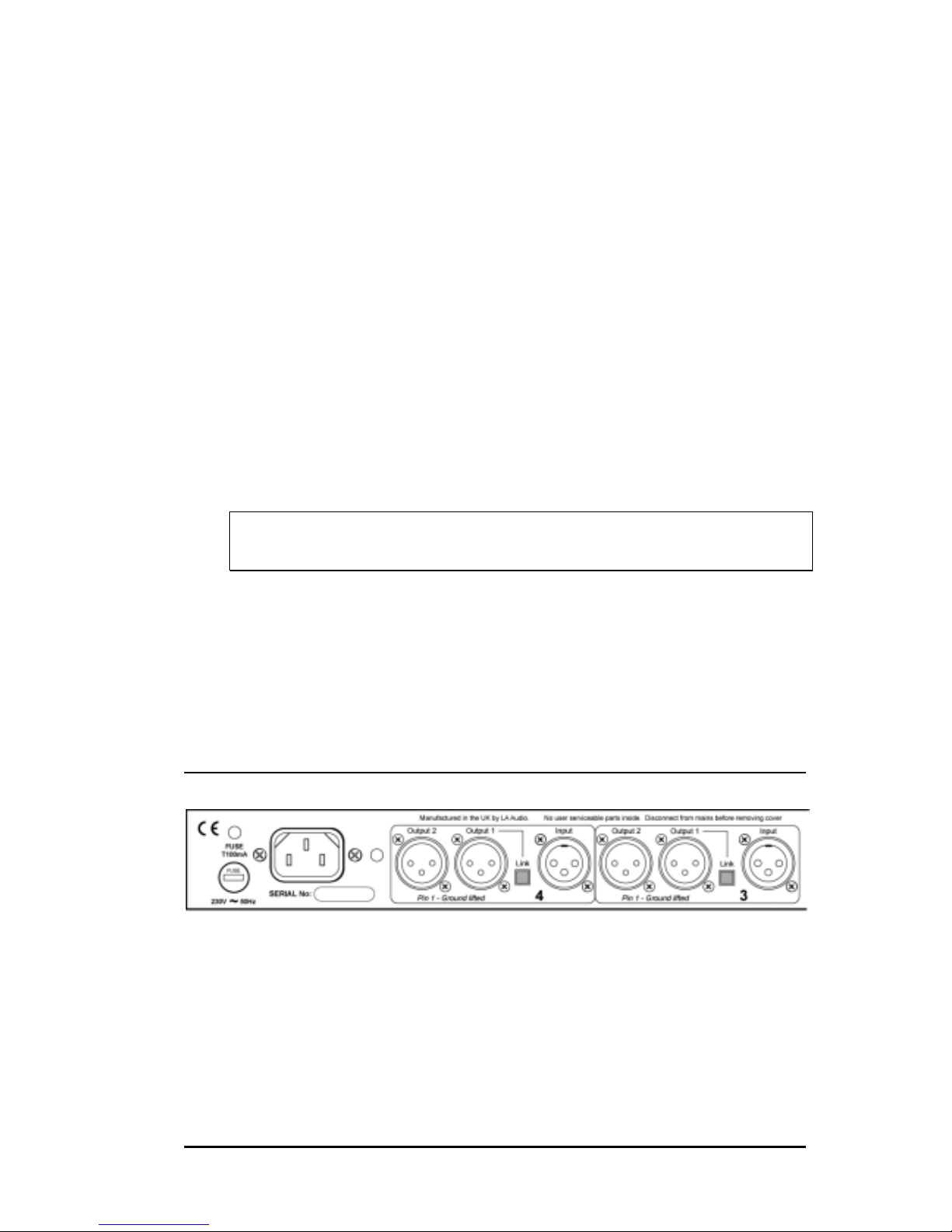
Each of the MS424 channels has an electronically balanced input, which may
be transformer balanced as an option, and four independently buffered
transformer balanced outputs on XLR connectors. Output '1' may be linked
directly to the input via a rear panel LINK switch on each channel. The unit
may also be configured, by way of internal links, to feed 8, 12 or 16 outputs
from any one input, allowing the MS424 to be used for press box applications.
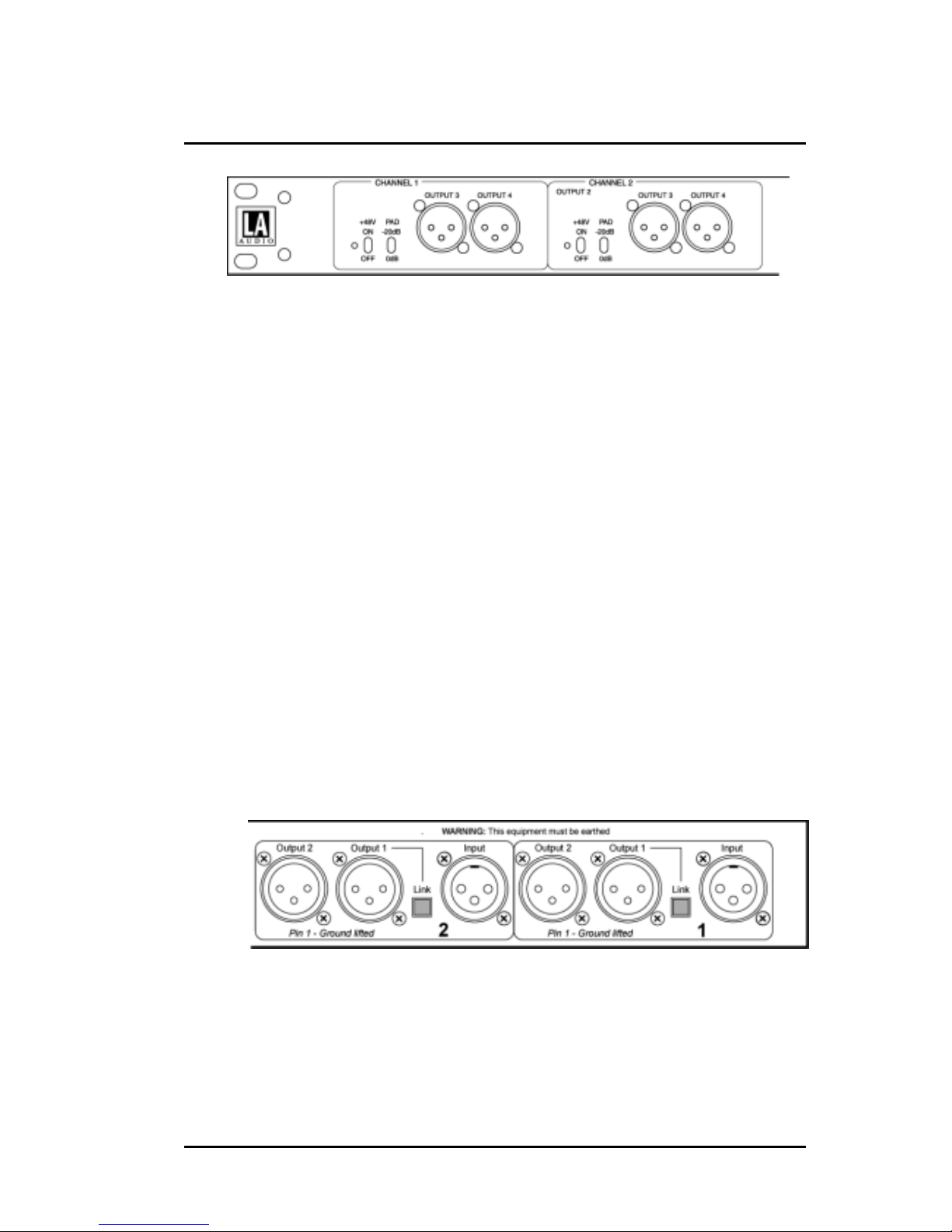
The front panel of the MS424 gives access to outputs 3 and 4 as well as
Phantom Power switching with phantom presence LED, and Pad switching for
line level signals. The Inputs and Outputs 1&2 are grouped on the rear panel
together with the Output 1 Link switches.
The MS424's internal power supply makes it ideally suited to smaller
installations where it becomes highly cost effective when compared to
externally powered alternatives. However the MS424 may also be used in
multi-channel applications, particularly when transformer isolation is required
for broadcast feeds.

MS424 5
2. TECHNICAL SPECIFICATIONS
2.1 ELECTRICAL
Frequency response:: 20 Hz to 20 kHz, +0, -0.5 dB
Input Impedance:: 2 kΩ
Maximum Input Level: 0 dBu (+20 dBu with Pad)
Equivalent Input Noise (EIN): better than -121 dBu
Output Source Impedance: less than 50 Ω
Output Load Impedance: 150 Ωto infinity
Gain: 0 dB (-20dB with Pad)
Total Harmonic Distortion (THD): better than 0.01 %
(1kHz, 150 Ωload)
Intermodulation Distortion: better than 0.01%
60Hz + 7kHz mixed 7:1 at 0dBu output
Power supply: 230Vac or 115Vac, 50/60Hz
*100Vac, 50/60Hz
Consumption: 16VA
2.2 PHYSICAL
Input Connector: XLR-F 3 Pin, Pin 2 = hot
Output Connectors: XLR-M 3 Pin, Pin 2 = hot
Power Connection: Detachable IEC 3 pin socket lead
Dimensions: 483 (19") W, 208 (8.2") D, 44 (1.75")H
Weight: Unit: 4kg Shipping: 4.8kg
Temperature Range: Operating: 0°C to 50°C
Storage: -30°C to 75°C
0dBu = 0.775Vrms
Owing to our continued development programme modifications may be
made to existing products, features or specification without notice.

MS424 6
3. INSTALLATION
3.1 INSPECTION AND UNPACKING
The MS424 has been carefully packed at our factory in a carton designed to
withstand handling in transit. Should the unit appear to have been damaged in
transit, notify your dealer immediately and do not discard any of the packing.
The carton should contain -
• The MS424
• Power cord - country specific, please check
• Operator Manual (this book)
3.2 OPERATING ENVIRONMENT
The MS424 is designed to operate between 0°C and 40°C (32-112°F) with
relative humidity no more than 80%. Should the units be installed in an
equipment rack, ensure that the ambient temperature conforms to these levels.
3.3 CE STANDARDS AND THE LOW VOLTAGE DIRECTIVE (LVD)
The MS424 has been designed to comply with the latest Electromagnetic
Compatibility (EMC) regulations. However we recommend you do not operate
the unit close to strong emitters of electromagnetic radiation such as power
transformers, motors, mobile telephones or radio transmitters.
The unit should only be connected to a power supply of the type described in
3.4 POWER REQUIREMENTS or as marked on the unit. Disconnect the mains
supply before removing any cover.
3.4 POWER REQUIREMENTS
The MS424 is factory configured for either 230V 50Hz ac or 115V 60Hz ac
mains operation. Please refer to the following diagram which shows the
transformer connections for 230V and 115V –

MS424 7
The rating of the rear panel fuse is as follows
230V 115V
T100mA T200mA Both are slow blow type
Please note:
If the fuse requires changing at any time please ensure the correct type is
fitted. An incorrect fuse could cause damage to the unit and may
constitute a fire hazard.
The detachable IEC mains lead connections to the appliance are coloured in
accordance with the following code:
Green-and-Yellow Earth
Blue Neutral
Brown Live
WARNING: THIS APPLIANCE MUST BE EARTHED
Please note:
A protective earth connection, made by way of the earth conductor in the
power cord, is essential for safe operation.
3.5 EXTERNAL CONNECTIONS
The Inputs on the Model MS424 are female XLR type connectors. These are
wired as follows -
XLR-F Pin 1 * Screen
Pin 2 Hot (+ve)
Pin 3 Cold (-ve)
* Pin 1 is ground lifted by a 100R resistor to Audio ground and by a 47nF

MS424 8
capacitor to Chassis ground. This configuration prevents ground loop hum and
ensures a low impedance path for RF (Radio Interference) away from the
audio.
Although the inputs are designed for 'balanced' signals either pin 2 or 3 can be
connected to pin 1 for unbalanced operation.
All outputs on the MS424 are balanced on male XLR type connectors. These
are wired as follows -
XLR-M Pin 1 * Screen
Pin 2 Hot (+ve)
Pin 3 Cold (-ve)
* Pin 1 is ground lifted - see above.
Although the inputs are designed for 'balanced' signals either pin 2 or 3 can be
connected to pin 1 for unbalanced operation.
3.6 SIGNAL LEVELS
The input to output voltage gain on the MS424 is 0dB. Maximum input signal
level will depend on the setting of the Pad switch.
0dB (down) position is for microphone levels and maximum input level is 0dBu.
The -20dB position should be used for line level signals. Maximum input level
is then +20dBu and voltage gain will be -20dB.
Maximum output level from the MS424 is +20dBu into a 600Ωload.

MS424 9
4. WARRANTY
Your MS424 has been manufactured to a high standard using quality
components. If correctly installed and operated the unit should give years of
problem free operation.
However in the event of a defect in material or workmanship causing failure of
the unit within one year of the date of original purchase we will agree to repair,
or at our discretion, replace any defective item without charge for labour or
parts. To receive service under this warranty it is necessary to return the unit to
an SCV authorised service centre or to the factory with a dated receipt as proof
of purchase. After repair the unit will be returned to you at our cost.
Limitations: This warranty does not cover damage resulting from accident or
misuse. The warranty is void unless repairs are carried out by an authorised
service centre. The warranty is void if the unit has been modified other than at
the manufacturers instruction. The warranty does not cover components which
have a limited life, such as valves, and which are expected to be periodically
replaced for optimal performance. We do not warrant that the unit shall operate
in any way other than as described in this manual.

MS424 10
5. DESCRIPTION OF CONTROLS
Phantom switch
Switches +48V from the internal power supply to the Input connector on the
rear panel.
To prevent the chance of damage to any external pieces of equipment, do not
use the +48V power option with unbalanced input sources i.e. those where pins
1 & 3 or 1&2 are connected together. To avoid loud and potentially damaging
electrical noise always turn down monitor speakers and connect your
microphone before switching phantom power on.
Phantom presence led
This led lights whenever Phantom Power is present at the Input connector.
This power can be internally or externally supplied.
Pad switch
Inserts a 20dB pad into the signal path. To be used when Line level signals are
inputted to the MS424.
OUTPUT 3 connector
Transformer balanced and isolated output.
OUTPUT 4 connector
Transformer balanced and isolated output.
Power led
The blue POWER indicator is lit whenever power is applied to the unit.
LINK switch
Pressing the LINK switch connects Output 1 directly to it's associated Input
connector. All 3 pins on the Output 1 XLR are affected.
OUTPUT 1 connector
Output 1 can be either a transformer split output or directly connected
(LINKed) to the Input.

MS424 11
OUTPUT 2 connector
Transformer balanced and isolated output.
6. OPTIONS
6.1 CONFIGURATION
Each channel of the MS424 consists an input stage and an output stage.
These are connected internally by jumper links which allow the MS424 to be
configured for the following options -
Option Configuration Channels
1 1 IN 4 OUT 4
2 1 IN 8 OUT 2
3 1 IN 12 OUT* 1
4 1 IN 16 OUT 1
* Channel 4 still available as 1 x 4
There are a pair of jumpers associated with each channel and two associated
with the internal buss.
6.2 CHANNEL JUMPERS
CHANNEL JUMPERS
The pair of jumpers for each channel select the channel to be Normal, Master
or Slave. The 3 jumper configurations are shown below.
Normal Master Slave
JP101& JP102, JP201 & JP202, JP301 & JP302, JP401 & JP402
Channel select jumpers as viewed from the front of the unit.
The function of these jumpers can be best understood by refering to the block
diagram on the following page -
NORMAL

MS424 12
The channel Input stage is connected directly to it's associated output stage.
This provides 1 input to 4 output splitting and is the Factory default setting.
MASTER
The channel Input and output stage are connected to the internal bus. The
Input signal is thus distributed to other output stages which have been
configured as slaves.
SLAVE
The channel Input is disabled and it's output connected to the internal bus. The
output stage now outputs signal from the internal bus.
+48V
Mic
Pad
Channel
jumpers
Input stage Output stage
+48V
Mic
Pad
Channel
jumpers
+48V
Mic
Pad
Channel
jumpers
+48V
Mic
Pad
Channel
jumpers
Bus
8/12
Bus
12/16
1
2
3
4
Internal buss

MS424 13
Block diagram of the MS424 showing the channel and bus option jumpers.
Channel Input to Output 1 LINK switching not shown - see diagram on
following page.
Only one Input stage at a time should be connected to the Internal Bus (Master
mode)
6.3 INTERNAL BUS JUMPERS
There are also two jumpers associated with the Internal Bus and determine the
number of split outputs available.
+48V
Mic
Pad
Input stage Output stage
1
1
2
3
4
Channel
jumpers
LINK
switch
Internal
bus
Block diagram of a MS424 channel showing LINK switch for Output 1.
The two bus jumpers allow the MS424 to be configured for 2 x 8, 1 x 12 (with 1
x 4) and 1 x 16 outputs.
812 12 16
JP203
BUS 8/12
JP303
BUS 12/16
Bus option jumpers as viewed from the front of the unit.

MS424 14
6.4 TRANSFORMER BALANCED INPUTS
Transformer balanced inputs can be fitted to provide galvanic isolation
between inputs and outputs. Although normally a factory build option,
transformers can be retro fitted by an Audient service centre.

MS424 15
7.0 APPLICATIONS
The MS424 is primarily designed to be used in theatres, fixed installations or
touring companies who require split feeds of the same signal. The active
design of the MS424 ensures that there is not loading or signal loss and as
each output is independent a fault on one will not affect the others.
The Inputs and Outputs 1 & 2 have been sited on the rear panel so that for a
typical installation using FOH (Front-of-House) and monitor consoles all
connections are made to the rear of the unit.
Typically Outputs 3 & 4 could be used for Outside Broadcast trucks and mobile
recording studios. Connections are made quick and easy by using standard
XLR connectors throughout.
A LINK switch is provided which connects the Input of each channel directly to
it's associated Output 1. This arrangement allows the original microphone
signal to feed the FOH desk whilst providing 3 split outputs.
By using the internal jumpers the MS424 can be configured as a 2 input 8
output, 1 input 12 output or 1 input 16 output splitter for a variety of
applications including multiple press feeds.
Table of contents
Other LA Audio Cables And Connectors manuals