Lab.gruppen NLB 60E User manual

Rev. 2.00
Operation manual
Item no. OM-NLB60E
NLB 60E
NomadLink Bridge and Network Controller

2 NLB 60E Operation Manual
1 CONTENTS .................................................................................................................................................2
2 IMPORTANT SAFETY AND OPERATION INSTRUCTIONS.....................................................................4
2.1 Explanation of graphical symbols ........................................................................................................4
2.2 Important Safety Instructions ..............................................................................................................4
2.3 Warning! ..............................................................................................................................................4
2.4 EMC / EMI ...........................................................................................................................................5
3 WELCOME...................................................................................................................................................6
4 INSTALLATION ...........................................................................................................................................7
4.1 Unpacking............................................................................................................................................7
4.2 Mounting .............................................................................................................................................7
4.3 Operating voltage ................................................................................................................................7
5 PANEL OVERVIEWS...................................................................................................................................8
5.1 Front-panel overview ...........................................................................................................................8
5.2 Rear-panel overview ............................................................................................................................8
6 CONNECTIONS TO AMPLIFIERS (NOMADLINK)....................................................................................9
6.1 Introduction..........................................................................................................................................9
6.2 Connecting the NLB 60E to the amplifiers..........................................................................................9
6.3 Nomadlink Connection Illustration.......................................................................................................9
6.4 NomadLink Wiring Notes ..................................................................................................................10
6.5 NomadLink network cable lengths ....................................................................................................10
6.6 GPI Connections................................................................................................................................10
7 CONNECTION TO PC FOR DEVICECONTROL .......................................................................................12
7.1 Introduction and network requirements ............................................................................................12
7.1.1 Introduction and network requirements ................................................................................12
7.1.2 Cable connections .................................................................................................................12
7.1.3 Direct connection to PC (peer-to-peer) ..................................................................................12
7.1.4 Connection through Local Area Network (LAN) ....................................................................12
7.2 TCP/IP network setup instructions ....................................................................................................12
7.2.1 TCP/IP address of the NLB 60E .............................................................................................12
7.2.2 TCP/IP address of the PC .......................................................................................................13
7.3 DeviceControl Software ....................................................................................................................14
8 ESTABLISHING A SECURE CONNECTION ............................................................................................15
8.1 Secure Connections ..........................................................................................................................15
8.1.1 Enabling secure connections ................................................................................................15
8.1.2 Set password ........................................................................................................................15
8.1.3 Adding additional subnets to a secure connection ...............................................................16
8.1.4 Disabling secure connections ................................................................................................16
8.1.5 Resetting passwords ...........................................................................................................17
8.1.6 Verify Secure Connection .....................................................................................................17
9 OPERATION AND CONFIGURATION......................................................................................................18
9.1 Introduction........................................................................................................................................18
9.2 Front-panel details .............................................................................................................................18
9.2.1 Navigation and display ............................................................................................................18
9.2.2 LEDs left of the display ..........................................................................................................18
9.2.3 Power ON/OFF.......................................................................................................................19
9.2.4 Network LEDs and Ethernet connection................................................................................19
9.3 Display navigation and features in detail............................................................................................20
9.3.1 Introduction ............................................................................................................................20
1 contents

NLB 60E Operation Manual 3
9.3.2 Homepage and Overview.......................................................................................................20
9.3.3 Mute Subnet...........................................................................................................................20
9.3.4 NLB 60E info ..........................................................................................................................20
9.3.5 Configuration ..........................................................................................................................23
9.3.5.1 NomadLink network settings ........................................................................................23
9.3.5.2 DHCP settings...............................................................................................................23
9.3.5.3 TCP/IP network settings ...............................................................................................23
9.3.5.4 General Purpose Input (GPI) settings............................................................................24
9.3.5.5 Power Sequence delay setting......................................................................................25
9.3.5.6 Front-panel PIN code lock setting .................................................................................25
9.3.5.7 Display contrast adjust ..................................................................................................25
9.3.5.8 Security .........................................................................................................................25
9.3.6 Subnet Info .............................................................................................................................25
9.3.7 Subnet Faults..........................................................................................................................26
9.3.8 Lock UI / Unlock UI.................................................................................................................27
10 APPENDIX .................................................................................................................................................28
10.1 Tree view of display structure............................................................................................................28
10.2 Firmware upgrade..............................................................................................................................31
10.3 Recovery via boot-loader mode.........................................................................................................31
10.4 FAQ....................................................................................................................................................32
11 NLB 60E TECHNICAL SPECIFICATIONS.................................................................................................33
12 WARRANTY ..............................................................................................................................................34
contents 1

4 NLB 60E Operation Manual
2.1 Explanation of graphical symbols
The lightning symbol within a triangle is intended to alert the user to the presence of un-insulated “dangerous voltage” within the amplifier’s
enclosure that may be of sufficient magnitude to constitute a risk of electric shock to humans.
The exclamation point within a triangle is intended to alert the user to presence of important operating and service instructions in the literature
accompanying the product.
WARNING CAUTION
2.2 Important Safety Instructions
Before using your amplifier, be sure to carefully read the applicable items of these operating instructions and the safety suggestions
Keep this manual for future reference.1.
Heed all warnings.2.
Follow all instructions.3.
Do not use this unit near water.4.
Do not spill water or other liquids into or on the unit. Do not operate the amplifier while wet or standing in liquid.5.
Clean only with dry cloth.6.
Do not block the air intake or exhaust ports. Install the unit in accordance with the instructions.7.
Do not operate the amplifier near heat producing devices such as radiators, heat registers, stoves or other apparatus that produce heat. Always8.
operate the unit with the chassis ground wire connected to the electrical safety earth. Do not defeat the safety purpose of a grounding-type plug. A
grounding type plug has two pins and a third grounding prong. The third prong is provided for your safety. If the provided plug does not fit into your
outlet, consult an electrician for replacement of the obsolete outlet.
Connect only to AC power outlets rated 100-120 V or 200-240 V, 50-60 Hz.9.
Do not use this amplifier if the power cord is broken or frayed. Protect the power cord from being walked upon or pinched particularly at the plugs10.
and the point where it exits from the apparatus.
Only use accessories specified by the manufacturer.11.
The unit is intended to use in a 19” rack. Follow the mounting instructions. When a rack on wheels is used, use caution when moving the loaded12.
rack to avoid injury from tipping over.
Unplug this apparatus during lightning storms or when unused for long periods of time.13.
Do not connect an amplifier output in parallel or series with any other amplifier’s output. Do not connect the amplifier output to any other voltage14.
source, such as battery, mains source, or power supply, regardless of whether the amplifier is turned on or off.
Do not run the output of any amplifier back into another channel’s input.15.
Refer all servicing to qualified service personnel. Servicing is required when the apparatus has been damaged in any way such as:16.
Power-supply cord or plug is damaged.•
Liquid has been spilled into the unit•
An object has fallen into the unit•
The unit has been exposed to rain or moisture•
The unit does not operate normally•
The unit was dropped or the enclosure is damaged•
17. Do not remove top or bottom covers. Removal of the covers will expose hazardous voltages. There are no user serviceable parts inside and
removal may void the warranty.
18. An experienced user shall always supervise this professional audio equipment, especially if inexperienced adults or minors are using th
equipment.
19. The mains plug is used as the disconnect device and shall remain readily operable. If mounted in a 19" rack causing the mains plug not being
readily operable, the mains plug for the entire rack must be readily operable.
20. The US National Differencescl.16.3 requires that NomadLinknetwork cables must be flame rated VW-1.
2.3 Warning!
To reduce the risk of fire or electrical shock, do not expose this apparatus to rain or moisture and objectfilled with liquids such as•
vases, should not be placed on the apparatus.
This apparatus must be earthed.•
Use a three wire grounding type line cord like the one supplied with the product.•
Be advised that different operating voltages require the use of different types of line cord and attachment plugs.•
Check the voltage in your area and use the correct type.•
To reduce risk of fire or electric shock, do not expose this
apparatus to rain or moisture.
To reduce the risk of fire or electric shock, do not remove
screws. No user-serviceable parts inside. Refer servicing to
qualified service personnel
2 IMPoRtAnt sAFetY AnD oPeRAtIon InstRUctIons

NLB 60E Operation Manual 5
See table below:•
Voltage Line plug according to standard
110-125 V UL817 and CSA C22.2 no 42.
220-230 V
CEE 7 page VII, SR section
107-2-D1/IEC 83 page C4.
240 V
BS 1363 of 1984.
Specification for 13A fused plugs and switched and
unswitched socket outlets
This equipment should be installed near the socket outlet and disconnection of the device should be easily accessible.•
To completely disconnect from AC mains, disconnect the power supply cord from the AC receptacle.•
The mains plug is used as the disconnect device and shall remain readily accessible. If mounted in a 19” rack causing the mains•
plug not to be easily accessible, then the mains plug for the entire rack must be readily accessible.
Do not install in a confined space.•
Do not open the unit - risk of electric shock inside.•
Caution:
You are cautioned that any change or modifications not expressly approved in this manual could void your authority to operate this•
equipment.
Service:
There are no user-serviceable parts inside.•
All service must be performed by qualified personnel.•
2.4 EMC / EMI
This equipment has been tested and found to comply with the limits for a Class B Digital device, pursuant to part 15 of the FCC rules.
These limits are designed to provide reasonable protection against harmful interference in residential installations. This equipment
generates, uses, and can radiate radio frequency energy and, if not installed and used in accordance with the instructions, may
cause harmful interference to radio communications. However, there is no guarantee that interference will not occur in a particular
installation. If this equipment does cause harmful interference to radio or television reception, which can be determined by turning
the equipment off and on, the user is encouraged to try to correct the interference by one or more of the following measures:
Reorient or relocate the receiving antenna.•
Increase the separation between the equipment and receiver.•
Connect the equipment to an outlet on a circuit different from that on which the receiver is connected.•
Consult the dealer or an experienced radio/ TV technician for help.•
For Users in Canada:
This Class B digital apparatus complies with Canadian ICES-003.
Cet appareil numérique de la classe B est conforme à la norme NMB-003 du Canada.
IMPoRtAnt sAFetY AnD oPeRAtIon InstRUctIons 2

6 NLB 60E Operation Manual
Thank you for choosing the Lab.gruppen NLB 60E
NomadLink Bridge and Network Controller. We are
confident that it will provide reliable service and
exceptional operating flexibility as the keystone
component in your NomadLink amplifier control
network.
Lab.gruppen’s proprietary NomadLink network allows
easy setup and control of Lab.gruppen C Series and
FP+ power amplifiers. The patented network topol-
ogy of NomadLink allows automatic detection and
addressing of multiple amplifiers, with extensive
monitoring and control enabled on a connected PC
running Lab.gruppen’s proprietary DeviceControl
software program.
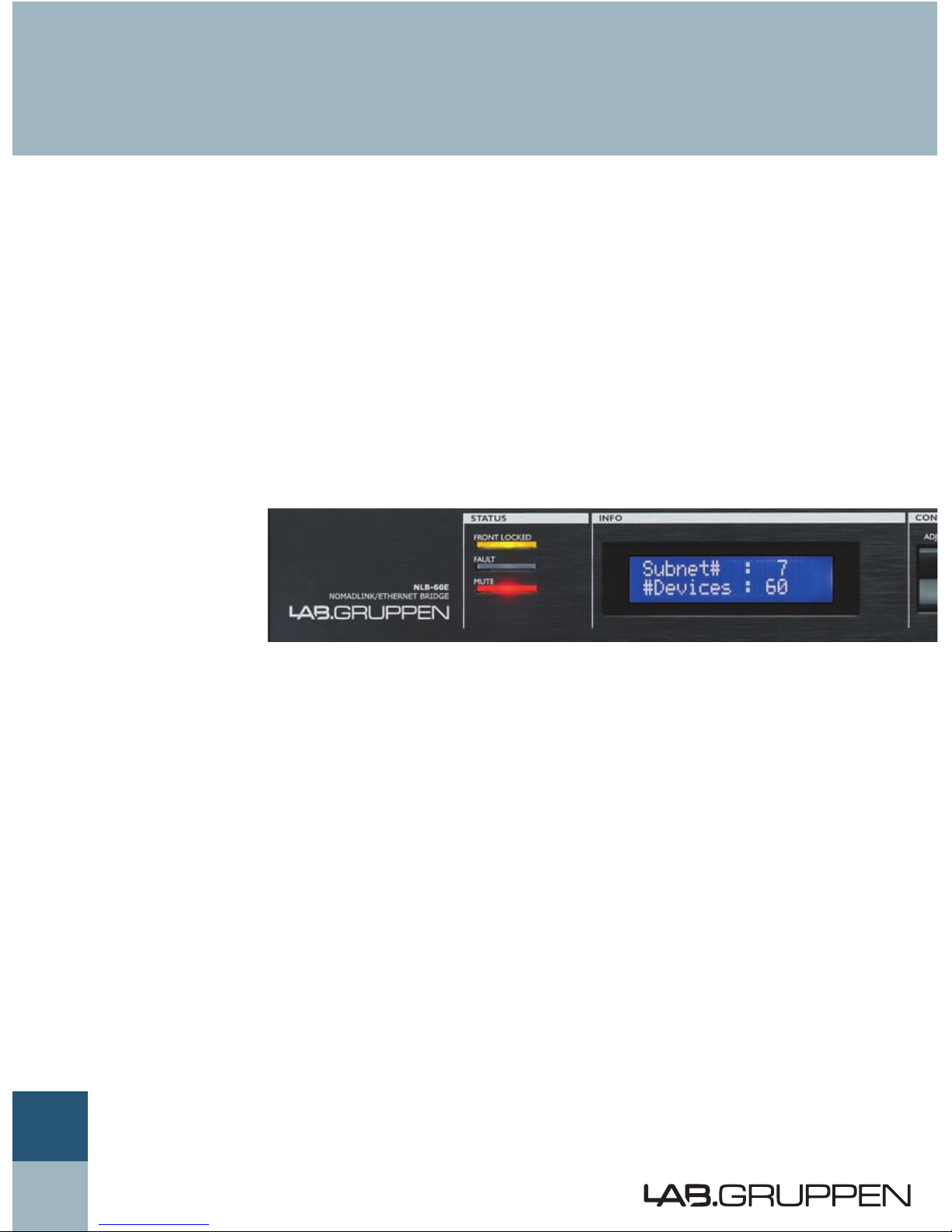
The NLB 60E serves a dual role. As a network bridge,
it provides the communication link between a host
PC running DeviceControl and the Lab.gruppen ampli-
fiers (as many as 60) connected to the NLB 60E
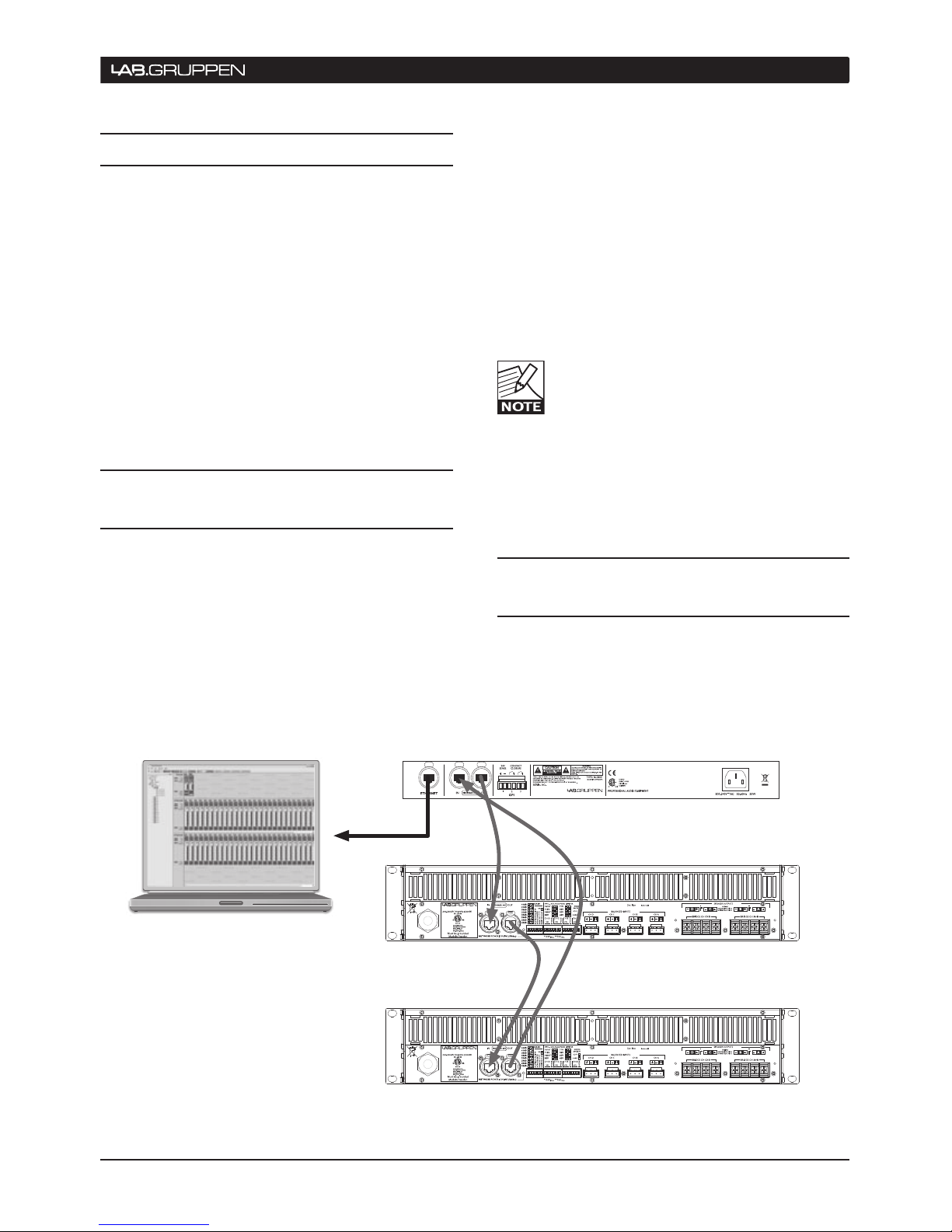
(referred to as a NomadlLink Subnet). Communication
between the PC and the NLB 60E is over Ethernet
using standard TCP/IP protocols; communication
between the NLB 60E and connected amplifiers is
via the robust NomadLink network.
The NLB 60E also serves as a stand-alone interface
for direct monitoring and control of many key func-
tions, including system muting and soloing, as well as
power ON/OFF utilizing the built in power sequencer.
These functions are accessible using the front-panel
displays and keypad user interface; no external PC
is required.
The NomadLink network offers a number of advan-
tages. First, phantom powering through the network
cables allows the software to detect devices that are
not currently turned on or connected to the mains.
This ensures very high reliability and redundancy,
while at the same time allowing connected amplifiers
to remain on standby with no power consumption.
Additionally, cable connections can be daisy-chained
for easier system setup. This approach reduces total
component costs, simplifies installation, and makes
daily operation more convenient. There is no need to
create a star topology using many switches as with,
for example, an Ethernet-based system. Individual
amplifier addresses do not need to be manually
entered. A daisy chain network-loop, in combination
with the automatic addressing of devices, enables
Lab.gruppen’s proprietary DeviceControl editor
software to automatically create a precise picture
of all connected devices and their relative position
in the chain.
NomadLink and DeviceControl work together to
provide a quick overview of the system layout,
allowing simple operation of a large group of
amplifiers. Installation time is kept to a minimum, and
operators have fast access to information needed
to solve problems during operation. At a glance, the
operator can simultaneously monitor all metering
data, as well as fault and warning indications, for all
amplifier channels on the subnet.
We suggest you read this manual in its entirety to
become fully acquainted with the features and func-
tions of the NLB 60E.
Lab.gruppen
Innovative Power Solutions
IMPORTANT NOTE: This manual
addresses operation of the NLB 60E as
installed with Firmware Version 2.0 or
greater and DeviceControl Software Version
2.0 or greater. Please visit www.labgruppen.com for
upgrades if you are using previous versions.
3 WeLcoMe

NLB 60E Operation Manual 7
4.1 Unpacking
Carefully open the shipping carton and check for
any noticeable damage. Every Lab.gruppen product
is tested and inspected before leaving the factory
and should arrive in perfect condition. If found to be
damaged, notify the shipping company immediately.
Only the consignee may institute a claim with the
carrier for damage incurred during shipping. Be sure
to save the carton and packing materials for the
carrier’s inspection. Should you ever need to ship the
NLB 60E, always use the original packaging.
4.2 Mounting
The NLB 60E is one rack unit high (1U) and will fit
into a standard EIA 19” rack. The depth is 208mm
(8.2”).
The weight is approximately 2.25 kg (5 lbs.)
The NLB 60E may be mounted directly on top of other
products; there is no need for spacing in between
units, though this might enable more convenient
cabling on the rear panel.
4.3 Operating voltage
The NLB 60E contains an auto -sensing PSU accepting
line voltage between 100V and 240V AC, 50/60Hz.
Please make sure that the mains supply connection
is grounded and mounted according to local regula-
tions.
Power consumption is 35W maximum. Actual
consumption will depend upon the number of devices
supplied with 48V phantom power through the
NomadLink network.
InstALLAtIon 4

8 NLB 60E Operation Manual
5.1 Front-panel overview
5.2 Rear-panel overview
5 PAneL oveRvIeWs
LED indicators:
Front UI locked,
Fault Mute Subnet
2x16 display
White on blue
Navigation keys:
SELECT,
ADJUST/SET,
EXIT/ESC,
ENTER/OK
NomadLink Subnet
Power ON/OFF
NomadLink and
Ethernet activity
LEDs
RJ45 Ethernet
connector
Ethernet on
EtherCon housed
RJ45 for standard
PC using TCP/IP
NomadLink
network In and Out
on EtherCon housed
RJ45
3x General Purpose Input (GPI) on 2-pole
Phoenix connectors:
GPI 1: Sensing High/Low Voltage
GPI 2 and 3: Contact closure
Mains input
100 V - 240 V
auto sensing

NLB 60E Operation Manual 9
6.1 Introduction
Connecting the NLB 6 0E to Lab.gruppen amplifiers in
a NomadLink network is a simple and straightforward
procedure. All connections are made with standard
(“straight”) Ethernet-type cables equipped with RJ45
connectors. Cable grade should be Cat5 or better.
Once connected, the NomadLink network allows
direct access and monitoring of up to 60 remotely
located Lab.gruppen amplifiers per NLB 60E. Many
system parameters can be accessed via the front
panel user interface. Optionally, the NLB 60E func-
tions as a network bridge between the NomadLink
network and a PC running DeviceControl editor
software.
6.2 Connecting the NLB 60E to
the amplifiers
The NLB 60E connects to the amplifiers through the
two rear panel ports labeled NOMADLINK IN and
OUT. Using a standard (“straight”) Ethernet cable,
connect the OUT port on the NLB 60E to the IN port
on the first amplifier in the network. Next, connect
the OUT port of the first amplifier to the IN port of
the second amplifier. Continue to “daisy chain” the
amplifiers, connecting the OUT port to the IN port of
the next amplifier, until all amplifiers are connected.
Complete the network loop by connecting the OUT
port of the last amplifier to the IN port on the NLB
60E.
The OUT port of the NLB 60E must be connected
to the IN port of the first amplifier to allow the De-
viceControl software to correctly identify devices
on the network.
IMPORTANT NOTE: Within restricted cable
distances, the NomadLink network will
function as a single-ended daisy-chain
without closing the loop. (The loop is closed
by connecting the last amplifier’s OUT port back to
the NLB 60E IN port). However, it is strongly recom-
mended that the loop be completed: doing so provides
a redundant signal path and improves communication
speed on the network.
6.3 NOMADLINK Connection
Illustration
connectIons to AMPLIFIeRs (noMADLInK) 6
IN OUT
NOMADLINK
IN OUT
NOMADLINK
NOMADLINK
IN OUT
ETHERNET
GENERAL
PURPOSE
INPUT, GPI
ETHERNET
"Crossed" RJ45 cable:
Between NLB 60E and PC.
"Straight" RJ45 cable:
Between Ethernet switch or hub and NLB 60E.
"Straight" RJ45 cables:
Between NLB 60E and amplifiers, and from
amplifier to amplifier in a subunit.
NOTE: Connection can be made to either
the front or rear panel or the NLB 60E.
Although two computers may be connected
to the NLB 60E simultaneously, only one is
allowed access to the subnet at a time.

10 NLB 60E Operation Manual
6.4 NomadLink Wiring Notes
All NomadLink ports on the NLB 60E, as well as por ts
on many NomadLink-equipped Lab.gruppen ampli-
fiers, are equipped with Neutrik EtherCon “XLR”
type connector housings. Connections may be made
with standard RJ45 connectors, or with the more
robust EtherCon connectors. The EtherCon housings
offer greater mechanical security and protection from
accidental damage.
For installations in the USA, all cables must carry the
VW-1 flame retardant rating (US National Differences
cl. 16.3).
When preparing custom Cat5 (Ethernet) cables for
the NomadLink application, all conductors in the
cable must be fully wired to the RJ45 connector. (No-
madLink uses conductor pairs that are not required
for a standard 100baseT Ethernet connection.)
6.5 NomadLink network cable
lengths
In installations where the NLB 60E is positioned at
some distance from the amplifier racks, or where
groups of amplifiers within a single subnet (up to 60
units) are located at some distance from each other,
the following general rules should be considered:
On the right side are typical examples of how
NomadLink network setups can be configured, with
maximum recommended distances shown:
• Rule 1:
The maximum cable length in between any two
devices may not exceed 300 meters / 980 feet.
• Rule 2:
In a non-closed-loop daisy-chained subnet the
total maximum cable length is 400 meters /
1300 feet.
• Rule 3:
In a closed-loop subnet the total maximum
cable length is 700 meters / 2300 feet.
6.6 GPI Connections
The NLB 60E is equipped with three General Purpose
Input (GPI) connectors on the real panel. Using these
connectors, the NLB 60 can relay commands from
external sources such as power sequencers or alarms
systems, initiating amplifier functions such as power
on/off or mute/unmute.
Two of the GPI connectors are of the contact closure
type. The third GPI connector is the voltage sensing
type (24V). All three use two-pole Phoenix connec-
tors.
More information on programming of the GPI
functions can be found in the Operation section at
9.3.5.4.
6 connectIons to AMPLIFIeRs (noMADLInK)

NLB 60E Operation Manual 11
connectIons to AMPLIFIeRs (noMADLInK) 6

12 NLB 60E Operation Manual
7.1 Introduction and network
requirements
More detailed information on connecting
to a PC is available in the DeviceControl
Users Manual. This manual is available for
download at www.labgruppen.com under
“Support” and “Product Documentation.”
7.1.1 Introduction and network requirements
The connection between the NLB 60E and the
host PC running DeviceControl editing software is
accomplished via standard Ethernet. The commu-
nication standards are the familiar TCP/IP network
communication protocols.
The host computer must be equipped with a standard
Ethernet (LAN) network interface. The NLB 60E
supports 100baseT and full duplex only.
7.1.2 Cable connections
The NLB 60E provides two parallel Ethernet connec-
tions: one on the front panel equipped with a standard
connector, and one on the rear panel equipped with
an EtherCon connector. The rear panel connector
is ideal for permanent connection to a Local Area
Network (LAN); the front panel RJ45 allows con-
venient temporary connection for maintenance and
service.
Although two computers may be connected to the
NLB 60E simultaneously, only one is allowed access
to the subnet at a time.
7.1.3 Direct connection to PC (peer-to-peer)
A direct connection between the PC and the NLB 60E
forms a “peer-to-peer” network. In most cases, this
connection will require use of the crossed Ethernet
cable. A crossed connection is necessary because the
NLB 60E is not an auto MDI/MDX sensing unit. Note
that many newer PCs now incorporate auto MDI/
MDX sensing, a feature which may allow peer-to-
peer connection using a standard “straight” Ethernet
cable. Refer to your computer’s documentation to
determine if this is this feature is enabled.
7.1.4 Connection through Local Area Network
(LAN)
If the PC is connected to the NLB 60E through a Local
Area Network (LAN), then a standard (“straight”)
Ethernet cable should be used. A typical LAN con-
nection incorporates a hub or switch.
7.2 TCP/IP network setup
instructions
7.2.1 TCP/IP address of the NLB 60E
The NLB 60 has following factory preset default
TCP/IP values:
IP: 192.168.1.166•
Subnet mask: 255.255.255.0•
Gateway: 0.0.0.0•
DHCP usage set to OFF•
Your host PC must be manually set to the same
subnet range (192.168.1.xxx). Alternately, you may
modify the NLB 60E IP address to allow connection
to the network. See Section 9.3.5.3 for detailed
instructions.
If you have more than one NLB 60E in your TCP/IP
network, then each NLB 60E must be assigned a
unique IP address. Therefore, the last three digits (the
.166 in the default configuration) must be changed
to a unique number between 1 and 255.
7 connectIon to Pc FoR DevIcecontRoL

NLB 60E Operation Manual 13
7.2.2 TCP/IP address of the PC
The following instructions on establishing a PC
connection to the NLB 60E may apply differently
depending on the version of the Windows Operating
System you are running. However, the IP parameters
stated will apply regardless of the Windows version
(no Mac OS X version available).
Except when using a DHCP server to automatically
obtain an IP address, you must manually set the
appropriate IP and Subnet Mask number. Using
Windows XP as an example, the following procedure
will establish the proper IP settings:
1. Go to START in lower left corner. Select: “Connect
to” and “Show all connections”
2. Select “Local Area Connection”. Select Properties
in the File menu, or by right-clicking. Highlight the
following selection: “Internet Protocol TCP/IP.” Click
on the “Properties” button.
You should see a window similar to the following:
3. Select “Use the following IP address.”
Enter a desired compatible address, such as:
19 2.16 8 .1.10 0
4. Click in “Subnet mask.” The following should
enter automatically: 255.255.255.0.
Leave “Default gateway” blank as this parameter
is not used.
connectIon to Pc FoR DevIcecontRoL 7

14 NLB 60E Operation Manual
7.3 DeviceControl Software
After the PC is connected to one or more NLB 60E
units in a valid Ethernet (TCP/IP) configuration,
you may launch the DeviceControl application.
DeviceControl can then either upload an amplifier
configuration from the NLB 60E subnet(s), open a
saved amplifier configuration, or create a new con-
figuration. Key features such as power ON/OFF and
amplifier channel muting will be controlled directly
from the DeviceControl windows. Please read the
DeviceControl Operation Manual for more details on
features and functionality of this software.
When DeviceControl is running and con-
nected to an NLB 60E, the front-panel
keypad commands on the NLB 60E’s will
be locked out. However GPI trigger com-
mands will not be locked out. All other control is
assumed by the DeviceControl software program.
The DeviceControl link must be removed by closing
the application to restore local control by the NLB
60E user interface. When the DeviceControl applica-
tion is closed the local control by the NLB 60E user
interface is restored.
7 connectIon to Pc FoR DevIcecontRoL
5. Click on OK. To verify that your settings are correct,
select and review the Support page.
The PC is now ready to connect to the NLB 60E when
the DeviceControl application is started.

NLB 60E Operation Manual 15
8.1 Secure Connection
NLB 60E bridge(s) in the NomadLink network-
can connect to one computer at a time running
DeviceControl software. However, if the preferred
or authorized computer is not currently connected,
any computer with DeviceControl installed may
access the NomadLink network as long as secure
connection functionality is inactive. When activated,
a secure connection restricts network access to a
DeviceControl installation with a password setting
that matches the password in the NLB 60E bridge.
A secure connection may be preferred in two
situations. First, a secure connection will prevent
unauthorized access to the NomadLink network:
only a DeviceControl application with a matching
password will be able to connect to the network.
Also, secure connections can simplify operation
and monitoring of two or more completely separate
NomadLink systems operating over the same LAN.
Several host computers can use the same network,
with each DeviceControl application accessing only
those NLB 60E bridges programmed with respective
matching passwords.
8.1.1 Enabling secure connections
Secure connection is available in DeviceControl ver-
sion 2.0 and above, and with NLB 60E firmware v
2.0 and above. Both are required. Secure connection
is disabled as default.
Enabling of a secure connection is a two-
step process. First, the secure connection
option must be enabled manually on each
NBL 60E using the front panel keypad. Then
a password must be set in DeviceControl for both
the host computer and all NLB 60E bridges with
secure connection enabled.
Once a secure connection is established in
DeviceControl, the secure connection will be retained
automatically with future software upgrades.
Enabling secure connection in the NLB 60E
Repeat the steps below for all NLB 60E bridges in
the system. DeviceControl must be offline to access
front panel functions of the NLB 60E.
Press the Select key on the NLB 60E and repeat1.
pressing until the Configuration menu appears.
Press OK.
Press Select and repeat pressing until Security2.
appears. Press OK. Press OK for Secure Conn.
After secure connection is enabled in the
NLB 60E bridges, it is important to imme-
diately enable secure connection in the
DeviceControl application. The connection
is not secure until both steps are completed.
8.1.2 Set password
From the main window, select File menu and1.
choose Settings.
Click on the Security tab.2.
Check the “Enable Secure Connection” (Figure3.
8.1).
Figure 8.1
Fill in a password in the “New Password” and4.
“Confirm New Password” fields (Figure 8.2).
Press “Set”.
A new pop up appears “Set NLB 60E’s5.
password?” Click on “Yes”.
The “Set NLB 60E Password” dialog appears.6.
Leave “Old Password” field empty. (No7.
password has yet been set in the NLB 60E).
estABLIsHInG A secURe connectIon 8

16 NLB 60E Operation Manual
Figure 8.2
Fill in “New Password” and “Confirm8.
Password” with the same password set in
step 4. These passwords must be identical to
establish connection between DeviceControl
and NLB 60E’s.
Verify that all NLB 60E’s are selected.9.
Press Set.10.
Press OK in the Settings dialog. The Secure11.
Connection is enabled.
8.1.3 Adding additional subnets to a secure
connection
Additional subnets may be added to an existing
secure connection as follows:
Enable the secure connection physically in the1.
additional NLB 60E as described in 6.1.1.
Start DeviceControl2.
Choose “Create a new configuration” in the3.
Quick Start menu.
From the main window, select Settings from4.
the File menu.
Click on the Security tab.5.
Click on “Change authentication password” for6.
NLB 60E
The “Change NLB 60E Password” dialog pops7.
up.
Leave “Old Password” field empty. (Noa.
password has yet been set in the newly
added NLB 60E’s).
“New Password” and “Confirm Password”b.
are filled in with the same password set
in step 8 in 6.1.2 above. These passwords
need to be the same to establish connection
between DeviceControl and the NLB 60E’s.
Verify that all added subnets are visible.c.
Press “Deselect All” and select the new
(added) subnets only.
Press “Set”.d.
8. Press “OK” in the Settings dialog. Secure
Connection is now enabled in the additional
NLB 60E’s.
You can verify that a secure connection has
been enabled by checking the NLB 60E
information log via the front panel menu
and display.
8.1.4 Disabling secure connections
Use this procedure if you no longer wish to have a
secure connection to the NomadLink network.
Disabling secure connection in the NLB 60E
The following steps must be repeated for each NLB
60E in the system.
Press the Select key on the NLB 60E front1.
panel until the Configuration menu appears in
the display. Press “OK”.
Press Select until Security menu appears. Press2.
“OK”.
Press “OK” for “Secure Conn.”.3.
Press on Adjust/Set until “Disable” appears.4.
Press “OK” to confirm.
The previously set password in the NLB
60E is reset (deleted) when the secure
connection is disabled. A new password
must be set in the NLB 60E when re-
enabling a secure connection.
Disabling secure connection in DeviceControl
Start DeviceControl1.
Choose “Create a new configuration” in the2.
Quick Start menu.
Select “File” and then “Settings…” from the3.
menu bar.
Click on the Security tab.4.
Uncheck the “Enable Secure Connection” box.5.
Type password in the “Disable secure6.
connection” dialog.
Upon completing step 6 above, the pass-
word is reset (deleted). A new password
must be entered in this DeviceControl in-
stallation when re-enabling a secure con-
nection.
8 estABLIsHInG A secURe connectIon

NLB 60E Operation Manual 17
8.1.5 Resetting passwords
Use the procedure below if you do not remember
your password and need to reset it.
Resetting the password in the NLB 60E
Repeat these steps for all NLB 60E’s in the sys-
tem:
Press the Select key on the NLB 60E front panel1.
until “Configuration” appears on the display.
Press “OK”.
Press Select until “Security” appears. Press2.
“OK”.
Press on Adjust/Set until “Reset Password?”3.
appears. Press “OK” to confirm.
Set new password following the procedure in4.
6.1.2 above.
Resetting the password in DeviceControl
The password in DeviceControl is deleted (disabled)
when Secure Connection is disabled by the procedure
described above. Authorization with the old (existing)
password is required before a new password can
be entered.
The password also is reset when DeviceControl is
uninstalled and reinstalled. Entry of the old password
is not required. However, depending on the Windows
configuration, uninstalling may require authorization
from the system administrator.
8.1.6 Verify Secure Connection
To verify the status of secure connection on the NBL
60Es the easiest way is to look at the upload dialog
(Figure 8.3).
Start DeviceControl1.
Choose “Upload configuration from network”2.
in Quick Start menu.
Verify the information in the “Upload3.
Configuration” dialog according to information
below
This information is also available in the “Set NLB
60E password” and “Change NLB 60E password”
dialogs.
Indicates that secure
connection is enabled and
that the password is NOT
set in this NLB 60E. This is
not a secure connection!
Indicates that secure
connection is enabled in
this NLB 60E
Figure 8.3
estABLIsHInG A secURe connectIon 8

18 NLB 60E Operation Manual
9.1 Introduction
The following section provides comprehensive information on operation of the NLB 60E, including configuration
of various network functions. Please read this section thoroughly to become familiar with the NLB 60E’s
features and functionality.
9.2 Front-panel details
9.2.1 Navigation and display
Use the six keys to the right of the 2x16 character
LCD screen to navigate through the menu views of
the NLB 60E. The views are organized as a tree-
structure. Selecting “OK” when the display shows
“→Enter” will take you into a new set of selections.
For an overview of all available displays, please
refer to the Appendix section. In brief, to navigate
the options you will:
Use the SELECT up/down arrows to scroll
•
through available views.
Press ENTER/OK to access the next menu
•
“down” or to confirm a selection.
Press EXIT/ESC to access the next menu “up”•
in the command tree. (This allows you to escape
a selection without changing settings.)
Use the Control ADJUST | SET up/down arrows•
to change parameter values in selected display
Some commands may need confirmation with
“OK” or be disregarded with “ESC”.
9.2.2 LEDs left of the display
Three primary status LEDs are located to the left of
the display.
FRONT LOCKED indicates that the front-panel user
interface is locked out. This occurs when Device-
Control is connected to the NLB 60E, or when the
password function has been selected to lock the
front-panel.
To unlock the front-panel user interface, either shut
down DeviceControl at the PC or select “Unlock
display” and enter the four-digit pin-code.
It is also possible to unlock the UI by pres-
sing and holding the ESC+OK buttons until
you reach the home screen when
powering up the NLB 60E.
9 oPeRAtIon AnD conFIGURAtIon

NLB 60E Operation Manual 19
oPeRAtIon AnD conFIGURAtIon 9
FAULT indicates that one or more devices (ampli-
fiers) on the NomadLink network have sensed a fault
condition. You may scroll through the Subnet faults to
see which unit is faulty, or connect the DeviceControl
application to access complete information on all
connected devices.
MUTE indicates that the entire subnet of detected
amplifiers is in Mute state. Locate the Mute/Unmute
display using the SELECT and OK buttons to change
the Mute state.
9.2.3 Power OFF/ON
The Power OFF/ON buttons enable the user to switch
the mains power state for ALL connected amplifiers
in the local subnet. A green LED above each button
indicates current status, either off or on. The power
sequence delay time, dictating the time between
power up activation of each consecutive amplifier
in a subnet, can be adjusted.
Please refer to section 9.3.5.5 Power Sequence
delay setting for more information on this
feature.
If an amplifier has been switched off
locally, and this was not the preconfigured
status, the NLB 60E will continue trying to
switch it back on.
9.2.4 Network LEDs and Ethernet
connection
The front-panel Ethernet connection is located at the
far right of the front-panel, adjacent to the network
status indicators.
The front-panel and rear-panel Ethernet connections
run in parallel, allowing connection of two PCs to the
NLB 60E. These two Ethernet connections operate
as a HUB.
Even though it is possible to connect two
PCs to the NLB 60E, only one is allowed
to access the subnet at a time.
The blue NOMADLINK LED illuminates when one
or more NomadLink-equipped amplifiers are con-
nected to the IN or OUT ports of the NLB 60E. A
flashing LED indicates communication activity on
the NomadLink network.
The orange ON-LINE LED indicates that a valid
Ethernet network has been detected AND that a
connected PC is running the DeviceControl applica-
tion for access and control of the NLB 60E.
The yellow ACTIVITY LED indicates active
communication between the DeviceControl applica-
tion and the NLB 60E.

20 NLB 60E Operation Manual
9.3 Display navigation and
features in detail
9.3.1 Introduction
The NLB 60E’s features are accessed, monitored,
and adjusted using the 2x16 character display and
associated keypad.
The display views are organized as a tree. The top
level comprises the following “headlines.” Pressing
the SELECT UP/DOWN keys moves through the
headlines. Pressing the ENTER/OK button in any
headline display will access a sub-display.
Lock UI?
Ok
Please read these sections thoroughly to become
familiar with the various views.
9.3.2 Homepage and Overview
On power-up, the NLB 60E will automatically inter-
rogate the NomadLink network and display Subnet
numbers and the total number of devices found on
the Subnet.
This view is the default “Homepage” that will appear
after a period of system inactivity. It is also the view
that is displayed when the NLB 60E’s front UI is
locked and unavailable for local operation.
The Subnet number is set on the NLB 60E’s
Configuration page. Each subnet must be
assigned a unique number.
9.3.3 Mute Subnet?
Select the “Mute Subnet?” display and press OK to
globally mute all channels of all amplifiers connected
to the NomadLink network.
When amplifiers are muted, the display will change
to:
Press OK to Unmute all connected amplifiers.
9.3.4 NLB 60E info
The NLB 60E Info pages are all “Read only” and are
provided for monitoring settings and performance.
To modify any settings, select the Configuration
section.
9 oPeRAtIon AnD conFIGURAtIon
Other manuals for NLB 60E
3
Table of contents
Popular Network Hardware manuals by other brands

Harman
Harman JBL Professional VL8A user guide

Cabletron Systems
Cabletron Systems HSIM-FE6 user guide

Milesight
Milesight UR32L quick start guide

Dazzle
Dazzle Hollywood DV-Bridge user guide

Motorola
Motorola 68436 - Vanguard 100I - Remote Access Server overview

GeoVision
GeoVision GV-Compact DVR V2 user manual