Labgear HDX60P User manual

User Guide
HDX60P
HDMI 60m Extender Kit with POE
over single CAT 5e/6/7
®

• To prevent re or shock hazard, do not expose any part of this device to rain
or moisture.
• This product is for indoor use only
• Do not expose the product to extreme heat
• Do not disassemble any of the units in this kit they contain no user
serviceable parts. Refer servicing to qualied personnel only.
• This device should be operated using only the AC/DC adaptor supplied with it.
• Do not overload wall outlets and extension cords as this can result in the risk
of re or electrical shock.
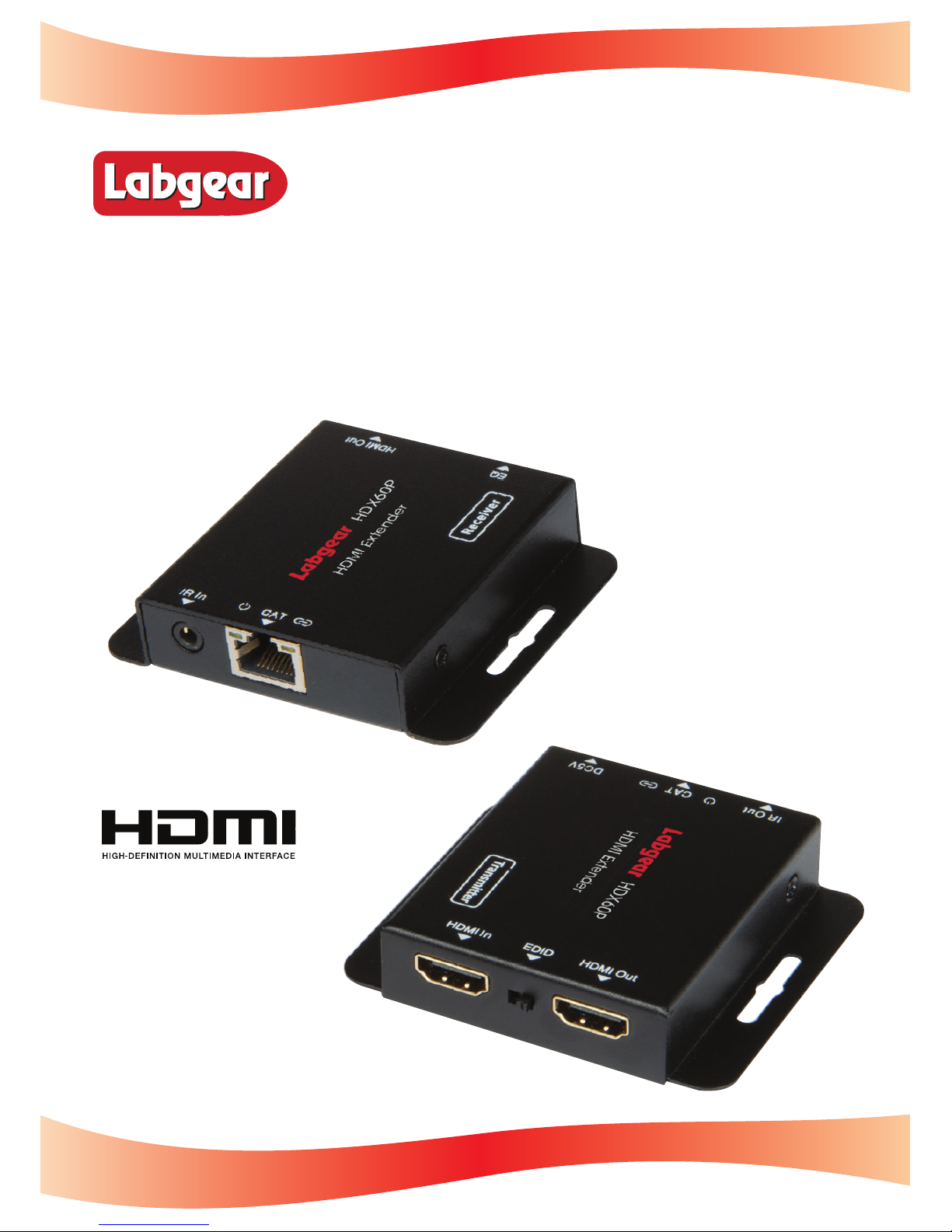
The HDMI Extender extends high denition video and audio signals and IR,
over a distance of up to 60m over a single CAT 5e/6/7 cable. It features EDID
management, which allows and encourages source and display “handshake” for
seamless integration. With only one cost eective CAT 5e/6/7 cable, high
denition sources with HDMI outputs can be connected to high denition
displays with HDMI inputs over long distances. Deep colour video, DTS-HD or
Dolby TrueHD audio are supported and compatible with the extender. In
addition, the extender is also equipped with bi-directional IR pass-through
which allows for source or display control.
The extender comprises two units: a transmitter and receiver. The transmitter is
used to capture the HDMI input with IR signals and sends the signals over a
single Cat 5e/6/7 Ethernet cable. The receiver equalizes the transmitted HDMI
signal and either reconstructs any IR control signals sent or sends IR control
signals back to the source via the Transmitter.
• Allows HDMI Audio/Video and IR signals to be transmitted over a single
CAT 5e/6/7 cable.
• Supports copy EDID from receiver display or loop out display.
• Allows for cascading via an additional HDMI loop out port.
• Supports ‘Power Over Ethernet’ function.
• Transmission Range: Extends 1080p resolution up to 60m over a single
CAT 5e/6/7 cable.
• Works with HDMI and HDCP compliant devices.
• Supports up to 1080p High Denition resolution.
• Compact design for an easy and exible installation.
General Safety
Features
Introduction
2

1x HDMI Transmitter
1x HDMI Receiver
1x Wideband IR Blaster and Cable
1x Wideband IR Receiver and Cable
1x 5V𝌂1A DC Power Supply Adaptor
1x Product Manual
Specications
Video Bandwidth: Single-link 165MHz (4.95Gbps)
Video Support: 480i/480p/720p/1080i/1080p @ 60Hz
Audio Support: Surround Sound (up to 7.1 ch) or stereo digital audio
Transmission Range: HD (1080p 24bit color) - up to 60m
Input TMDS Signal: 3.3V
Input DDC Signal: 5.0 V/P-P
ESD Protection: +/- 8 kV (air-gap discharge)
+/- 4 kV (contact discharge)
HDMI Connector: Type A 19 pin female
RJ45 Connector: WE/SS 8P8C
3.5mm Connector: (TX and RX) IR Receiver/IR Blaster
Housing: Metal enclosure
Power Supply: 1x 5V𝌂1A
Power Consumption: 1.5 watts (TX); 1.0 watts (RX)
Operating Temperature: 0~40°C
Storage Temperature: -20~60°C
Relative Humidity: 20~90% RH (no condensation)
Extender Kit Contents
3

!
①HDMI IN: Via an HDMI cable connects to the HDMI output port of your
source equipment such as DVD/Blu-ray players or set top box.
②EDID SWITCH: Switched to the right, the extender will copy the EDID
information for the display connected to the HDMI loop out to the
source equipment. Switched to the left, the extender will copy the EDID
information of the display connected to the Receiver to the source.
③HDMI OUT: Via an HDMI cable connects to the HDMI input of a local
display such as an HDTV.
④IR OUT: Connection for the IR Blaster cable included in the pack for IR signal
transmission. Place the IR Blaster in direct line-of-sight of the equipment to
be controlled. Use the sticky pad to attach to a suitable surface.
⑤POWER LED: Indicates when the device is connected to a power supply.
⑥CAT: Via CAT 5e/6/7 Ethernet cable connects the transmitter with the CAT
input of the receiver.
⑦LINK LED: Indicates when the device is connected to an HDMI source.
⑧DC 5V: Connection for 5V DC power adaptor which is plugged into a
mains socket.
Transmitter - Sockets and Switches
4

Receiver - Sockets and Switches
!
①EQ SWITCH: HDMI Receiver equaliser switch.
②HDMI OUT: Via an HDMI cable connects to the HDMI input of a display such as
an HDTV.
③IR IN: Connection for the IR Receiver cable included in the pack for IR signal
reception. Place the IR Receiver in a position in direct line-of-sight of the
remote control. Use the sticky pad supplied to attach to a suitable surface.
④POWER LED: Indicates that the receiver is receiving power over the
Ethernet cable
⑤CAT: CAT: Via CAT 5e/6/7 Ethernet cable connects the receiver with the CAT
output of the transmitter.
⑥LINK LED: Indicates when the HDMI signal from the transmitter is stable.
If the image on the display is ickering
or ashing, adjust the EQ switch to
improve the cable skew.
MAX (7) sets the strongest HDMI signal
level for the longest possible
transmission length while MIN (0) sets
the weakest HDMI signal level for the
shortest transmission length.
Adjust the signal level from 0-7 to
achieve optimum video quality.
Receiver Equaliser Distance Adjustment
5
Recommended EQ setting
Switch Positions
Cable Length
!
!
Under 15m
!
15-30m
!
30-40m
!
40-50m
Recommended Equaliser Settings

Connection and Operation
1. Connect a source such as a Blu-Ray Player, game console, A/V Receiver, Cable
or Satellite Receiver, etc. to the HDMI input on the Transmitter.
2. Connect a display such as an HDTV or HD Projector to the HDMI output on
the Receiver.
3. Connect a single CAT 5e/6/7 up to 60m long to the CAT output of the
Transmitter and the other end to the CAT input of the Receiver.
4. Plug the power supply into the Transmitter DC5V power socket and plug the
power adaptor into a mains socket.
5. Switch on the source and display(s).
At this point any displays connected to the Transmtter and Receiver should
display the signal from the source device connected to the Transmitter.
If no signal is being displayed, check the Receiver EQ switch setting is suitable for
the cable length.
If a display is not receiving a good signal, use the EDID switch to copy the EDID
information to the source (see the EDID section on page 4) or access the display’s
menu and adjust the resolution (lowest to highest until a good picture displayed).
N.B. A 24Hz vertical refresh rate may work better than 60 Hz or higher.
Use the source remote pointed at the IR Receiver sensor to test IR functionality.
If the IR remote function is not responding, check that the IR Blaster and Receiver
are placed correctly and are plugged into the correct IR sockets on the Extender
Receiver and Transmitter.
DVD
TX
IR Receiver
HDMI Cable HDMI CableNetwork Cable
RX
HDMI Cable
TV
Troubleshooting
6

The HDX60P kit is supplied with a wideband IR Blaster and Receiver they
respectively emit or recieve IR signals in the 30-60kHz range.
IR Blaster (TX)
To control the source: Plug the IR Blaster into the IR OUT socket on the
transmitter, place the Blaster as close as possible in front of the IR sensor of
the source device.
To control the display: Plug the IR Blaster into the IR IN port of the Receiver,
place the Blaster as close as possible in front of the IR sensor of the display.
When you are happy with the position of the IR Blaster you can x it in
position by peeling of the backing paper of the sticky pad on the base and
sticking it in position.
IR Receiver (RX)
To control the source: Plug the IR Receiver into the IR IN port of the receiver
unit and place the IR Receiver close to the display and where the source
remote control is in line-of-sight.
To control the display: Plug the IR Receiver into the IR OUT socket of the
transmitter and place the IR Receiver in a position where it is able to receive
signals from the display remote control.
When you are happy with the position of the IR Receiver you can x it in
position sticking the sticky pad supplied to the base of the IR Receiver and
xing it in position.
Wideband IR Blaster and Receiver
7

For further information, please contact:
Customer Careline:
08457 573 479
Local rate: UK Only
www.labgear.co.uk
© Labgear 2015. v1 MK42 0NX
Waste electrical and electronic products must
not be disposed of with household waste.
Please recycle where facilities exist.
Check with your Local Authority for recycling advice.
Technical Support
8
Table of contents
Other Labgear Extender manuals
Popular Extender manuals by other brands

REMO Electronics
REMO Electronics BAS CONNECT 3.0 Quick user guide

KSB
KSB Hya-Solo DV Series Installation & operating manual

DKT Comega
DKT Comega WAVE2 IPLoA-MESH-PLC-W quick start guide

NTI
NTI XTENDEX Series Installation and operation manual

Amped Wireless
Amped Wireless REC10 user guide

KIKA
KIKA KATALYST user manual