Labkotec MD-1 User manual

Labkotec Oy
Myllyhaantie 6 1
FI-33960 PIRKKALA
FINLAND
Tel: +358 29 006 260
Fax: +358 29 006 1260 11.02.2010
Internet: www.labkotec.fi
1/5
Copyright © 2010 Labkotec Oy We reserve the right for changes without notice
Labko MD-1
Current loop to RS-232 converter
Installation Instructions

Labko MD-1 D30646Ae
Installation Instructions
Copyright © 2010 Labkotec Oy 2/5 We reserve the right for changes without notice
TABLE OF CONTENTS
1. GENERAL..................................................................................................................................................... 3
2. TECHNICAL DATA....................................................................................................................................... 3
3. INSTALLATION AND ELECTRICAL CONNECTIONS................................................................................ 3
3.1 CONSTRUCTION .................................................................................................................................... 3
3.2 CONNECTIONS....................................................................................................................................... 4
3.3 TO BE NOTICED DURING INSTALLATION............................................................................................ 4
3.4 CABLING.................................................................................................................................................. 4
3.4.1 CABLING BETWEEN LPS-1 POWER SUPPLY AND MD-1........................................................... 4
3.4.2 RS-232 CONNECTION................................................................................................................... 4
4. SERVICE AND REPAIR ............................................................................................................................... 4
APPENDIX 1 CONNECTION DIAGRAM ......................................................................................................... 5

Labko MD-1 D30646Ae
Installation Instructions
Copyright © 2010 Labkotec Oy 3/5 We reserve the right for changes without notice
1. GENERAL
MD-1 is a two-way protocol converter for
communication between Labko 3000 probes and
a computer program. MD-1 converts the RS-232
protocol information to a 20 mA digital current
loop data e.g. from a PC for Labko 3000 probes
and vice versa.
Figure 1. Typical installation with multiple tanks
2. TECHNICAL DATA
MD-1
Supply voltage
230 V 50/60 Hz
Fuse:5 x 20 mm 100 mAT
(EN 60127-2/3)
The device does not have a
mains switch.
Power consumption 2 VA
Electrical safety EN 61010-1 CAT II, Class II
Operating tempe
r
ature -10 ºC…+50 ºC
Input RS-232
Output 20 mA active digital curent
loop
Protection level
Input/Output
1500 VDC
Dimensions 125 mm x 125 mm x 75 mm
(L x H x D)
Enclosure IP 65, material polycarbonate
EMC Emission
Immunity
EN 61000-6-3
EN 61000-6-2
3. INSTALLATION AND ELECTRICAL
CONNECTIONS
3.1 CONSTRUCTION
FIgure 2. Installation dimensions
The enclosure can be wall-mounted. The
mounting holes are located in the base plate of
the enclosure, beneath the mounting holes of the
front cover.

Labko MD-1 D30646Ae
Installation Instructions
Copyright © 2010 Labkotec Oy 4/5 We reserve the right for changes without notice
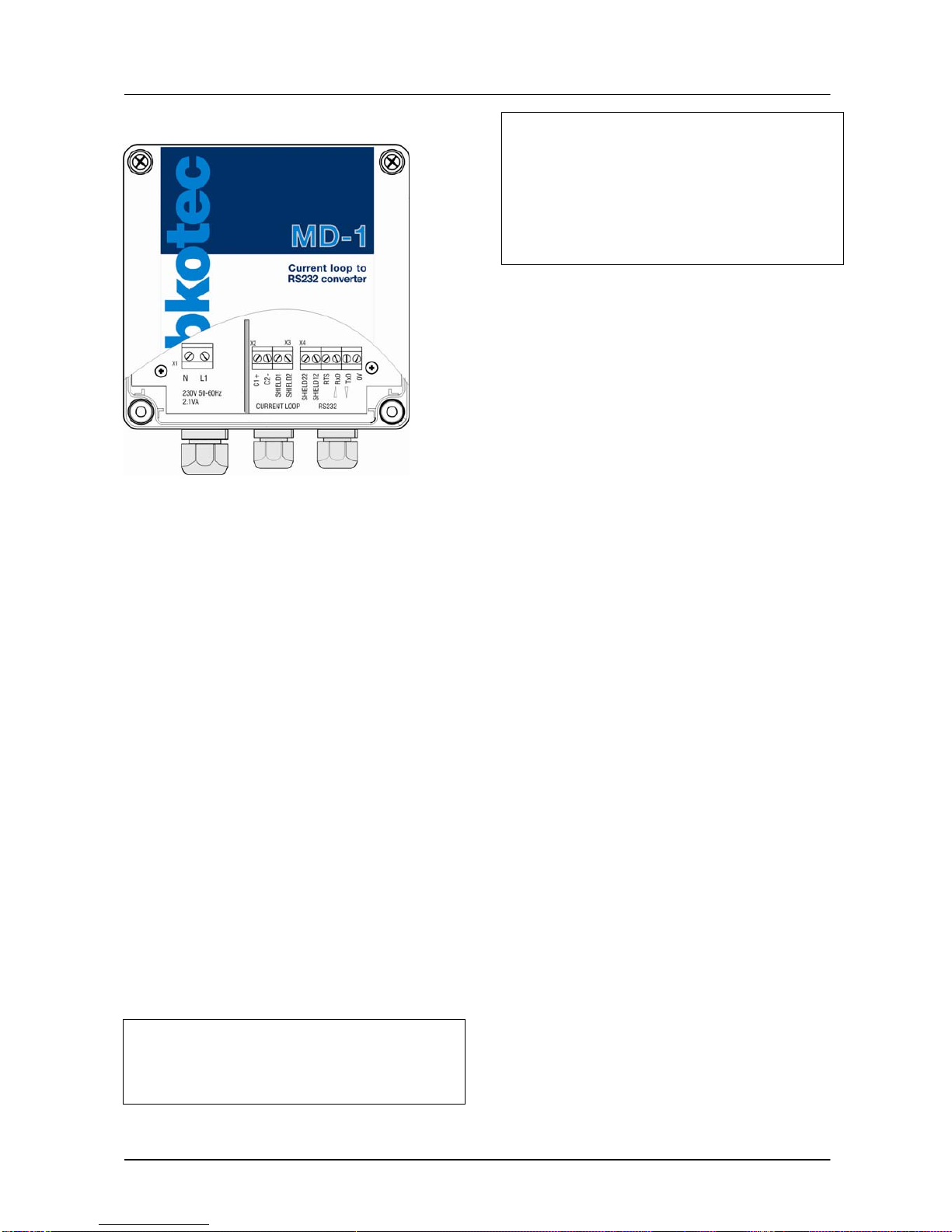
3.2 CONNECTIONS
Figure 3. Electrical connections
X1:
L1 = mains supply phase line conductor
N = mains supply neutral conductor
X2-X3: (CURRENT LOOP)
C1(+) = (+) pole of the current loop
C2(-) = (-) pole of the current loop
SHIELD1 = shield for a cable pair
SHIELD2 = common cable shield
X4-X5-X6: (RS-232)
SHIELD22 = cable shield
SHIELD12 = for equipotential grounding
RTS = handshake signal
RxD = receive signal
TxD = transmit signal
0V = RS-232 signal ground
3.3 TO BE NOTICED DURING
INSTALLATION
The device does not have a mains switch:
A mains switch (250 VAC / 1 A), which isolates
both mains conductors (L1, N), must be
installed near MD-1 unit for service and repair
purposes.
In installations, where digital current loops of
multiple LPS-1 units are connected in series,
all units (max. 9 units/switch) can be fed
through the same switch.
Labelling must be provided immediately
adjacent to the switch to permit rapid
identification of the circuit or group of circuits
thereby controlled.
3.4 CABLING
3.4.1 CABLING BETWEEN LPS-1 POWER
SUPPLY AND MD-1
Shielded instrument cable with two conductors
with minimum of 0,5 mm2 cross sectional area, is
suitable for carrying the digital current loop
between the LPS-1 power supply and MD-1.
The maximum length of the current loop is 400 m
when using the type of cable mentioned above.
The current loop conductors of the cable are
connected to CURRENT LOOP terminals C1 (+)
and C2 (-).
In order to achieve the best possible protection for
electromagnetic interference, it is recommended
to use a cable, which has a common shield for the
whole cable in addition to the shield for the cable
pair, see attached drawing D30611. In this case
one must notice that different shield types must be
electrically separated from each other.
The shield for a cable pair is connected to
SHIELD1 and the common shield to SHIELD2. In
case there is only one shield, connect it to
SHIELD2.
Please check also the LPS-1 Installation and
Operating Instructions.
3.4.2 RS-232 CONNECTION
The maximum length of a RS-232 cable according
to RS-232 standard is 16 m with a baud rate of
19,2 kbaud (maximum cable capacitance 2200
pF). In practice the cable can be somewhat longer
due to baud rate of 300 baud when
communicating with Labko 3000 probes.
In case the RS-232 cable shield is not grounded
in the D-connector end (e.g. at the PC), the shield
can be grounded e.g. by connecting the MD-1
conductor SHIELD12 to grounding or true earth.
4. SERVICE AND REPAIR
The mains fuse (marked 80 mAT) can be replaced
with another 5 x 20 mm / 80 mAT glass tube fuse
complying with EN 60127-2/3.

Labko MD-1 D30646Ae
Installation Instructions
Copyright © 2010 Labkotec Oy 5/5 We reserve the right for changes without notice
APPENDIX 1.
CONNECTION DIAGRAM:
Labko 3000, LPS-1 ja MD-1

Table of contents
Popular Media Converter manuals by other brands

TRENDnet
TRENDnet TFC-110S20D3 Specifications

Verus Engineering
Verus Engineering 987 Cayman Install manual

Leybold vacuum
Leybold vacuum TURBO.DRIVE 400 operating instructions

SIIG
SIIG AV-GM01U3-S1 manual

Bose
Bose WAVE MUSIC SYSTEM-SOUND LINK owner's guide

Baumer
Baumer HUBNER POG 10 Series Mounting and operating instructions

Keene Electronics
Keene Electronics APTUS 1 Instructions for use

Lika
Lika Posicontrol IF55 LIN CB Series Mounting instructions

Avenview
Avenview C-SC-UNI user guide

BARIX
BARIX Retail Player S400 user manual

Link electronics
Link electronics PDR-870 Specification sheet

Transition Networks
Transition Networks CSEFE1012-100 user guide