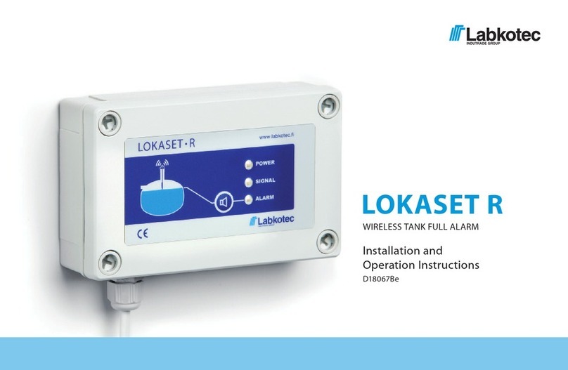
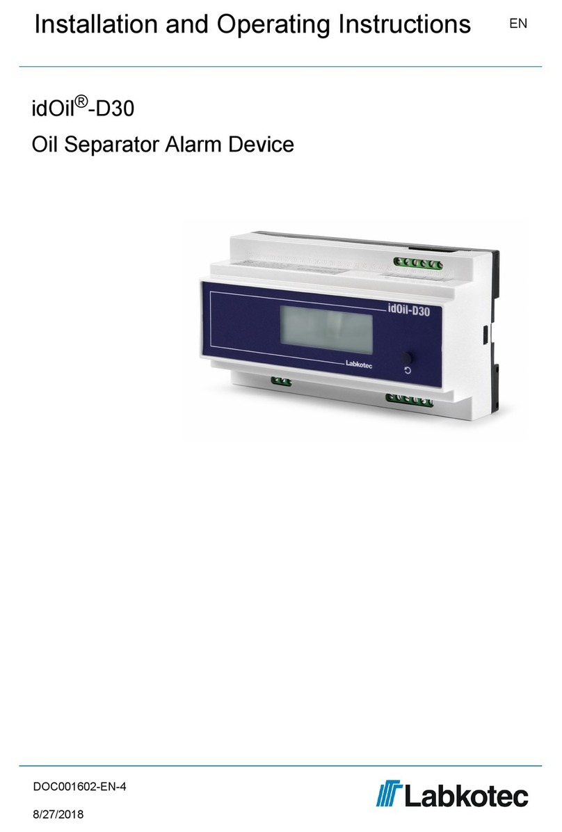
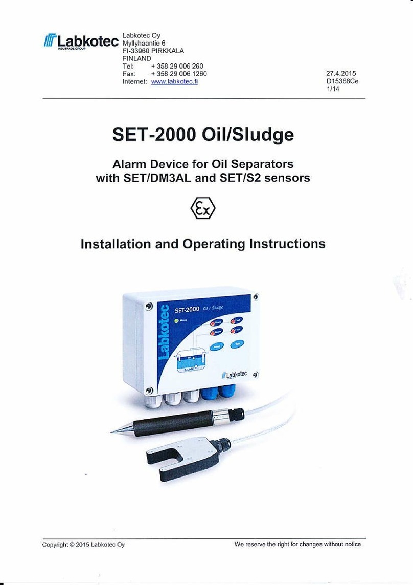
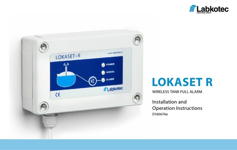
Labkotec idOil Solar User manual

idOil® Solar
Solar Powered Oil and Sand Separator Alarm
Device
Installation and Operating Instructions EN
DOC001599-EN-3
11/21/2019

Table of contents
4
4
4
4
5
5
5
5
5
6
6
7
7
8
8
8
9
10
10
11
11
11
12
12
12
12
13
13
15
15
15
16
17
17
19
19
21
22
23
24
27
27
1. General information about the manual . . . . . . . . . . . . . . . . . . . . . . . . . . . . . . . . . . . . . . . . . . . . . . . . . . .
1.1. Markings and symbols . . . . . . . . . . . . . . . . . . . . . . . . . . . . . . . . . . . . . . . . . . . . . . . . . . . . . . .
1.2. Conformity of the product . . . . . . . . . . . . . . . . . . . . . . . . . . . . . . . . . . . . . . . . . . . . . . . . . . . . .
1.3. Limitation of liability . . . . . . . . . . . . . . . . . . . . . . . . . . . . . . . . . . . . . . . . . . . . . . . . . . . . . . . . .
2. Safety and the environment . . . . . . . . . . . . . . . . . . . . . . . . . . . . . . . . . . . . . . . . . . . . . . . . . . . . . . . . . . . .
2.1. General safety instructions . . . . . . . . . . . . . . . . . . . . . . . . . . . . . . . . . . . . . . . . . . . . . . . . . . . .
2.2. Intended use . . . . . . . . . . . . . . . . . . . . . . . . . . . . . . . . . . . . . . . . . . . . . . . . . . . . . . . . . . . . . .
2.3. Transport and storage . . . . . . . . . . . . . . . . . . . . . . . . . . . . . . . . . . . . . . . . . . . . . . . . . . . . . . .
2.4. Installation and commissioning . . . . . . . . . . . . . . . . . . . . . . . . . . . . . . . . . . . . . . . . . . . . . . . .
2.5. Repair . . . . . . . . . . . . . . . . . . . . . . . . . . . . . . . . . . . . . . . . . . . . . . . . . . . . . . . . . . . . . . . . . . . .
2.6. Decommissioning and disposal . . . . . . . . . . . . . . . . . . . . . . . . . . . . . . . . . . . . . . . . . . . . . . . .
3. Product description . . . . . . . . . . . . . . . . . . . . . . . . . . . . . . . . . . . . . . . . . . . . . . . . . . . . . . . . . . . . . . . . . .
3.1. General . . . . . . . . . . . . . . . . . . . . . . . . . . . . . . . . . . . . . . . . . . . . . . . . . . . . . . . . . . . . . . . . . .
3.2. Device operation . . . . . . . . . . . . . . . . . . . . . . . . . . . . . . . . . . . . . . . . . . . . . . . . . . . . . . . . . . .
3.3. System components . . . . . . . . . . . . . . . . . . . . . . . . . . . . . . . . . . . . . . . . . . . . . . . . . . . . . . . . .
3.3.1. Solar panel and battery . . . . . . . . . . . . . . . . . . . . . . . . . . . . . . . . . . . . . . . . . . . . . .
3.3.2. idOil-30 Battery Control Unit . . . . . . . . . . . . . . . . . . . . . . . . . . . . . . . . . . . . . . . . . .
3.3.3. idOil-OIL Oil Sensor . . . . . . . . . . . . . . . . . . . . . . . . . . . . . . . . . . . . . . . . . . . . . . . .
3.3.4. idOil-SLU Sludge Sensor . . . . . . . . . . . . . . . . . . . . . . . . . . . . . . . . . . . . . . . . . . . .
3.3.5. idOil-LIQ High Liquid Level Sensor . . . . . . . . . . . . . . . . . . . . . . . . . . . . . . . . . . . .
3.3.6. Flashing Beacon . . . . . . . . . . . . . . . . . . . . . . . . . . . . . . . . . . . . . . . . . . . . . . . . . .
3.3.7. Main Power Switch . . . . . . . . . . . . . . . . . . . . . . . . . . . . . . . . . . . . . . . . . . . . . . . .
4. Installation . . . . . . . . . . . . . . . . . . . . . . . . . . . . . . . . . . . . . . . . . . . . . . . . . . . . . . . . . . . . . . . . . . . . . . . .
4.1. Installing idOil Solar Control Unit . . . . . . . . . . . . . . . . . . . . . . . . . . . . . . . . . . . . . . . . . . . . . .
4.2. General installation instructions for sensors . . . . . . . . . . . . . . . . . . . . . . . . . . . . . . . . . . . . . .
4.2.1. Installing the idOil-LIQ high liquid level sensor . . . . . . . . . . . . . . . . . . . . . . . . . . .
4.2.2. Installing the idOil-OIL sensor . . . . . . . . . . . . . . . . . . . . . . . . . . . . . . . . . . . . . . . .
4.2.3. Installing the idOil-SLU sludge sensor . . . . . . . . . . . . . . . . . . . . . . . . . . . . . . . . . .
5. Connections . . . . . . . . . . . . . . . . . . . . . . . . . . . . . . . . . . . . . . . . . . . . . . . . . . . . . . . . . . . . . . . . . . . . . . .
5.1. Connection diagrams . . . . . . . . . . . . . . . . . . . . . . . . . . . . . . . . . . . . . . . . . . . . . . . . . . . . . . .
5.1.1. Connection with a single-sensor cable connector . . . . . . . . . . . . . . . . . . . . . . . . .
5.1.2. Connection with a two-sensor cable connector . . . . . . . . . . . . . . . . . . . . . . . . . . .
5.1.3. Connection with a three-sensor cable connector . . . . . . . . . . . . . . . . . . . . . . . . . .
5.2. Explanations of connection diagrams . . . . . . . . . . . . . . . . . . . . . . . . . . . . . . . . . . . . . . . . . . .
6. Commissioning . . . . . . . . . . . . . . . . . . . . . . . . . . . . . . . . . . . . . . . . . . . . . . . . . . . . . . . . . . . . . . . . . . . .
6.1. Simple commissioning . . . . . . . . . . . . . . . . . . . . . . . . . . . . . . . . . . . . . . . . . . . . . . . . . . . . . .
6.2. Commissioning through the browser-based user interface . . . . . . . . . . . . . . . . . . . . . . . . . .
6.2.1. Establishing a WLAN connection . . . . . . . . . . . . . . . . . . . . . . . . . . . . . . . . . . . . . .
6.2.2. System settings . . . . . . . . . . . . . . . . . . . . . . . . . . . . . . . . . . . . . . . . . . . . . . . . . . .
6.2.3. Sensor naming and identification . . . . . . . . . . . . . . . . . . . . . . . . . . . . . . . . . . . . .
7. Operation . . . . . . . . . . . . . . . . . . . . . . . . . . . . . . . . . . . . . . . . . . . . . . . . . . . . . . . . . . . . . . . . . . . . . . . . .
7.1. Local display and alarms . . . . . . . . . . . . . . . . . . . . . . . . . . . . . . . . . . . . . . . . . . . . . . . . . . . .
Installation and Operating Instructions | idOil Solar 2/58
DOC001599-EN-3

28
28
28
29
30
31
32
33
34
34
35
36
37
37
39
40
41
42
44
45
45
46
47
47
48
49
49
50
51
52
52
52
52
53
53
54
55
55
56
57
58
7.2. Resetting an alarm . . . . . . . . . . . . . . . . . . . . . . . . . . . . . . . . . . . . . . . . . . . . . . . . . . . . . . . . .
7.3. Using the browser-based user interface . . . . . . . . . . . . . . . . . . . . . . . . . . . . . . . . . . . . . . . . .
7.3.1. Home screen . . . . . . . . . . . . . . . . . . . . . . . . . . . . . . . . . . . . . . . . . . . . . . . . . . . . .
7.3.2. Menu list . . . . . . . . . . . . . . . . . . . . . . . . . . . . . . . . . . . . . . . . . . . . . . . . . . . . . . . .
7.3.2.1. Alarm log . . . . . . . . . . . . . . . . . . . . . . . . . . . . . . . . . . . . . . . . . . . . . . .
7.3.2.2. Inspection . . . . . . . . . . . . . . . . . . . . . . . . . . . . . . . . . . . . . . . . . . . . . . .
7.3.2.3. Inspection log . . . . . . . . . . . . . . . . . . . . . . . . . . . . . . . . . . . . . . . . . . . .
7.3.2.4. Language . . . . . . . . . . . . . . . . . . . . . . . . . . . . . . . . . . . . . . . . . . . . . . .
7.3.2.5. Date and time . . . . . . . . . . . . . . . . . . . . . . . . . . . . . . . . . . . . . . . . . . . .
7.3.3. Settings menu . . . . . . . . . . . . . . . . . . . . . . . . . . . . . . . . . . . . . . . . . . . . . . . . . . . .
7.3.3.1. Customer data . . . . . . . . . . . . . . . . . . . . . . . . . . . . . . . . . . . . . . . . . . .
7.3.3.2. Inspection settings . . . . . . . . . . . . . . . . . . . . . . . . . . . . . . . . . . . . . . . .
7.3.3.3. Alarm settings . . . . . . . . . . . . . . . . . . . . . . . . . . . . . . . . . . . . . . . . . . . .
7.3.3.4. Relay settings . . . . . . . . . . . . . . . . . . . . . . . . . . . . . . . . . . . . . . . . . . . .
7.3.3.5. Software update . . . . . . . . . . . . . . . . . . . . . . . . . . . . . . . . . . . . . . . . . .
7.3.3.6. Restoring factory settings . . . . . . . . . . . . . . . . . . . . . . . . . . . . . . . . . . .
7.3.3.7. WLAN settings . . . . . . . . . . . . . . . . . . . . . . . . . . . . . . . . . . . . . . . . . . .
7.3.3.8. Low power mode settings . . . . . . . . . . . . . . . . . . . . . . . . . . . . . . . . . . .
7.3.3.9. 3G settings (idOil-30 3G model only, option) . . . . . . . . . . . . . . . . . . . .
7.4. Operating idOil Solar with mobile phone . . . . . . . . . . . . . . . . . . . . . . . . . . . . . . . . . . . . . . . .
7.4.1. Setting telephone numbers and telephone number queries (TEL) . . . . . . . . . . . .
7.4.2. Name of the device or location (NAME) . . . . . . . . . . . . . . . . . . . . . . . . . . . . . . . .
7.4.3. Time (CLOCK) . . . . . . . . . . . . . . . . . . . . . . . . . . . . . . . . . . . . . . . . . . . . . . . . . . . .
7.4.4. Timed message interval (TXD) . . . . . . . . . . . . . . . . . . . . . . . . . . . . . . . . . . . . . . .
7.4.5. Measurement interval (MI) . . . . . . . . . . . . . . . . . . . . . . . . . . . . . . . . . . . . . . . . . . .
7.4.6. Listening interval (LI) . . . . . . . . . . . . . . . . . . . . . . . . . . . . . . . . . . . . . . . . . . . . . . .
7.4.7. Operating voltage alarm limit setting (VLIM) . . . . . . . . . . . . . . . . . . . . . . . . . . . . .
7.4.8. Alarm information query (M) . . . . . . . . . . . . . . . . . . . . . . . . . . . . . . . . . . . . . . . . .
7.4.9. Test idOil Solar functions with the sensors . . . . . . . . . . . . . . . . . . . . . . . . . . . . . .
8. Maintenance . . . . . . . . . . . . . . . . . . . . . . . . . . . . . . . . . . . . . . . . . . . . . . . . . . . . . . . . . . . . . . . . . . . . . .
8.1. Functional test . . . . . . . . . . . . . . . . . . . . . . . . . . . . . . . . . . . . . . . . . . . . . . . . . . . . . . . . . . . .
8.1.1. Test function . . . . . . . . . . . . . . . . . . . . . . . . . . . . . . . . . . . . . . . . . . . . . . . . . . . . .
8.1.2. Functional test with sensors . . . . . . . . . . . . . . . . . . . . . . . . . . . . . . . . . . . . . . . . .
8.2. Maintenance measures . . . . . . . . . . . . . . . . . . . . . . . . . . . . . . . . . . . . . . . . . . . . . . . . . . . . .
8.3. Troubleshooting . . . . . . . . . . . . . . . . . . . . . . . . . . . . . . . . . . . . . . . . . . . . . . . . . . . . . . . . . . .
9. Technical and safety data . . . . . . . . . . . . . . . . . . . . . . . . . . . . . . . . . . . . . . . . . . . . . . . . . . . . . . . . . . . .
10. Appendices . . . . . . . . . . . . . . . . . . . . . . . . . . . . . . . . . . . . . . . . . . . . . . . . . . . . . . . . . . . . . . . . . . . . . .
10.1. Factory settings for idOil Solar . . . . . . . . . . . . . . . . . . . . . . . . . . . . . . . . . . . . . . . . . . . . . . .
10.2. Connector Flange for idOil Solar . . . . . . . . . . . . . . . . . . . . . . . . . . . . . . . . . . . . . . . . . . . . .
10.3. idOil Solar Wiring Diagram . . . . . . . . . . . . . . . . . . . . . . . . . . . . . . . . . . . . . . . . . . . . . . . . . .
10.4. idOil Solar EU Declaration of Conformity . . . . . . . . . . . . . . . . . . . . . . . . . . . . . . . . . . . . . . .
Installation and Operating Instructions | idOil Solar 3/58
DOC001599-EN-3

1. General information about the manual
This manual is an integral part of the product.
Please read the manual before using the product.
Keep the manual available for the entire duration of the product’s life span.
Provide the manual to the next owner or user of the product.
Please report any errors or discrepancies related to this manual before commissioning
the device.
1.1. Markings and symbols
Safety-related markings and symbols
This marking warns of a possible hazard. Failing to observe the safety instructions in
question may result in injury or death.
This marking warns of a fault or hazardous situation. Failing to observe the safety
instructions in question may result in injury or device breakage.
This marking warns of a possible fault. Failing to observe the safety instructions in question
may result in device or system breakage or erroneous operation.
This marking emphasises an issue that requires special attention during installation and
when using the device in an explosive atmosphere.
Informative markings and symbols
This marking highlights essential information.
►This marking refers to a user measure.
1.2. Conformity of the product
The EU declaration of conformity and the product’s technical specifications are integral
parts of this document.
All of our products have been designed and manufactured with due consideration to the
essential European standards, statutes and regulations.
Labkotec Oy has a certified ISO 9001 quality management system and ISO 14001
environmental management system.
1.3. Limitation of liability
Due to continuous product development, we reserve the right to change these operating
instructions.
The manufacturer cannot be held liable for direct or indirect damage caused by neglecting
the instructions provided in this manual or directives, standards, laws and regulations
regarding the installation location.
The copyrights to this manual are owned by Labkotec Oy.
Installation and Operating Instructions | idOil Solar 4/58
DOC001599-EN-3

2. Safety and the environment
2.1. General safety instructions
The plant owner is responsible for the planning, installation, commissioning, operation,
maintenance and disassembly at the location.
Installation and commissioning of the device may be performed by a trained professional
only.
Protection of operating personnel and the system is not ensured if the product is not used in
accordance with its intended purpose.
Laws and regulations applicable to the usage or the intended purpose must be observed.
The device has been approved for the intended purpose of use only. Neglecting these
instructions will void any warranty and absolve the manufacturer from any liability.
2.2. Intended use
The idOil alarm system is intended for monitoring liquid levels particularly in oil and sand
separators.
The system consists of a control unit and connected sensors that have been installed in the
oil or sand separator. The sensors can be placed in a zone 0 explosive atmosphere, but the
control unit must be positioned in a safe area.
A more specific description of the product’s operation, installation and use is provided later
in this manual.
The device must be used in accordance with the instructions provided in this document.
Other use is counter to the product’s purpose of use. Labkotec cannot be held liable for any
damage caused by using the device in violation of its purpose of use.
2.3. Transport and storage
Check the packaging and its content for any possible damage.
Ensure that you have received all the ordered products and that they are as intended.
Keep the original package. Always store and transport the device in the original packaging.
Store the device in a clean and dry space. Observe the permitted storage temperatures. If
the storage temperatures have not been presented separately, the products must be stored
in conditions that are within the operating temperature range.
2.4. Installation and commissioning
If the temperature in the installation environment is expected to exceed +40°C, the
temperature tolerance of the supply voltage and relay connection cable must be at least
+80°C. Otherwise, any cable that meets the applicable electrical regulations can be used
as the supply voltage and relay connection cable.
The internal temperature of the device can be 10°C higher than the ambient temperature.
This must be taken into account in the cabling of the device.
The idOil control unit must not be installed in potentially explosive areas, but a sensor
connected to it may be installed in potentially explosive atmospheres of zones 0, 1 and 2.
In potentially explosive area installations, the national regulations and appropriate
standards IEC/EN 60079-25 Intrinsically safe electrical systems “i” and/or IEC/EN 60079-
14 Explosive atmospheres - Electrical installations design, selection and erection must all
be followed.
Installation and Operating Instructions | idOil Solar 5/58
DOC001599-EN-3

If it is possible that static electricity can cause hazards in the measurement environment,
equipotential bonding must be attended according to the regulations concerning potentially
explosive atmospheres. Equipotential bonding is done by connecting all conductive parts to
the same potential e.g. in a junction box. Equipotential bonding system must be grounded.
The instructions concerning the inspection and maintenance of Ex equipment contained in
the standards IEC/EN 60079-17 and IEC/EN 60079-19 should be observed when
executing service, inspection or repair procedures in potentially explosive atmospheres.
See Technical specifications; Connection values and Appendix; System diagram.
2.5. Repair
The device may not be repaired or modified without the manufacturer’s permission. If the
device exhibits a fault, it must be delivered to the manufacturer and replaced with a new
device or one repaired by the manufacturer.
2.6. Decommissioning and disposal
The device must be decommissioned and disposed of in compliance with local laws and
regulations.
Installation and Operating Instructions | idOil Solar 6/58
DOC001599-EN-3

3. Product description
3.1. General
The idOil Solar is a solar-powered alarm and communication unit for monitoring the levels
of liquid hydrocarbon, sludge, or high levels in oil and sand separators, in locations where
mains power is unavailable.
This user manual includes installation and operating instructions for the following idOil Solar
versions:
idOil Solar 3G
idOil Solar 3G with a Beacon
idOil Solar Beacon
Typical applications for the above mentioned idOil Solar versions are illustrated in the
following figure.
idOil Solar Oil
Alarm for oil
separators:
idOil Solar
Sludge Alarm for
sand separators:
idOil Solar
Oil/Sludge Alarm
for combined oil
and sludge
alarm:
idOil Solar Hi
Level/Oil Alarm
for combined
high level and oil
alarm:
idOil Solar Hi
Level/Oil/Sludge
Alarm for
combined high
level, oil and
sludge alarm:
1. idOil Solar
Control Unit
2. idOil-OIL
sensor
3. Cable
connector
4. Sensor
mounting
supplies
1. idOil Solar
Control Unit
2. idOil-SLU
sensor
3. Cable
connector
4. Sensor
mounting
supplies
1. idOil Solar
Control Unit
2. idOil-OIL
sensor
3. idOil-SLU
sensor
4. Cable
connector
5. Sensor
mounting
supplies
1. idOil Solar
Control Unit
2. idOil-LIQ
sensor
3. idOil-OIL
sensor
4. Cable
connector
5. Sensor
mounting
supplies
1. idOil Solar
Control Unit
2. idOil-OIL
sensor
3. idOil-SLU
sensor
4. idOil-LIQ
sensor
5. Cable
connector
6. Sensor
mounting
supplies
Figure 1. Application examples
Installation and Operating Instructions | idOil Solar 7/58
DOC001599-EN-3

3.2. Device operation
The idOil Solar remains deactivated most of the time, which means that it consumes very
little power. The device initiates at predetermined measurement intervals, in order to
perform the sensor measurements. When equipped with a 3G modem, the device also
starts listening at predeterminined intervals, to receive any possible setting commands and
simultaneously reports measurement values.
In case of an alarm, idOil Solar will either initiate a flashing beacon, or sends a
text message (SMS) to pre-set phone numbers, or both. All alarms are also visible locally, in
the idOil Solar Control Unit, during the short wake-up period.
The system's power consumption depends on the pre-set measurement and transmission
intervals, as well as the number of alarms.
More information about the device operation is available in the Operation chapter.
3.3. System components
The idOil Solar Control unit consists of a lockable IP65 polycarbonate housing, containing a
solar panel, idOil-30 Battery Control Unit with an in-built charge controller, a lead acid
battery (12 V / 7 Ah) and a main switch.
Any combination of fail-safe idOil-sensors, namely the idOil-OIL oil sensor, idOil-SLU sludge
sensor and idOil-LIQ high liquid level sensor, can be connected to the system. The standard
sensor cable length of a sensor is 5 meters and extendable to at least 500 meters.
Each alarm unit and sensor combination can be equipped with a 3G communication
module, a flashing Xenon beacon or both.
1. Solar panel
2. Control unit idOil-30 Battery or
Control unit idOil-30 Battery 3G
3. Main switch
4. Battery 12 V / 7 Ah
5. Flashing beacon (option)
Figure 2. System components - idOil Solar Control unit
3.3.1. Solar panel and battery
The solar panel charges the lead acid battery which powers the idOil-30 alarm unit.
Charging of battery is controlled by an idOil-30 built-in solar panel charge controller.
In normal use (under factory settings) there is no need to recharge or replace the battery
during its natural life time, due to the sophisticated low-power function of the system.
Battery life is normally about 5 years.
Installation and Operating Instructions | idOil Solar 8/58
DOC001599-EN-3

The idOil Solar will function for at least 6 months without any sunlight. When the idOil Solar
is equipped with a xenon beacon, the operational time will be much less in case of an alarm
(see Xenon beacon below).
Please note that the battery life, and operational time of the idOil Solar depends on many
things, such as the amount of solar energy per day and previous days, temperature, battery
age and the idOil Solar system settings. Operational times presented in this document are
best estimates in particular cases.
3.3.2. idOil-30 Battery Control Unit
The idOil Solar operations are controlled by the idOil-30 Battery or idOil-30 Battery 3G
control unit. The idOil-30 takes care of the low-power system functions, measures
sensor, and controls the flashing beacon and 3G communication functions. The idOil-30
Battery includes a built-in solar panel charge controller, which takes care of the solar panel
and battery charging.
The idOil-30 is an Ex-barrier and power supply unit for the sensors in oil and sand
separators.
The idOil-30 Battery 3G version includes a built-in 3G modem and an external 3G antenna.
A separate external antenna is also an option, if signal quality is a problem. The user is able
to set and modify the settings of the device via text messages (SMS).
The idOil-30 operational settings are pre-set at the factory. The factory settings can be
changed via the in-built browser user interface. The browser user interface is accessible via
local WLAN connection between the control unit and a smartphone, tablet or laptop. For
more information, see idOil-30 installation and operating instructions DOC001699.
The display, test button and interfaces of the idOil-30 control unit are described in the
following figure.
1. Local display
2. Test and reset button
3. Lead-through for supply voltage
4. Lead-throughs for relays (2 pcs)
5. Lead-throughs for sensors (3
pcs, blue)
6. 3G antenna (only in 3G version)
Figure 3. idOil-30 Battery - features
Installation and Operating Instructions | idOil Solar 9/58
DOC001599-EN-3

3.3.3. idOil-OIL Oil Sensor
The idOil-OIL oil sensor is installed into the light liquid storage
chamber and gives an alarm when the chamber is filled to a
pre-determined level. The sensor is normally fully immersed in
water.
Insert the sensor into the separator using the access point
provided by the separator manufacturer. The sensor gives an
alarm, at the earliest when the upper electrode is in oil, and at
the latest when the sensor is totally immersed in a non-
conductive liquid . In other words, it is totally separated from
the water.
The sensor can be mounted suspended by a cable from the
ceiling of the separator. Please check the correct installation
depth from the instructions of the oil separator as well.
The function is based on the measurement of the electrical
conductivity of the surrounding liquid – water conducts
electricity more efficiently than oil.
The idOil-OIL sensor can be installed in a zone 0, 1 or 2 potentially explosive (Ex) area,
e.g. oil separator.
3.3.4. idOil-SLU Sludge Sensor
The idOil-SLU sensor is installed in the separator or tank and it
gives an alarm when sludge reaches the sensor. The sensor is
normally immersed in water.
The idOIL-SLU sensor gives an alarm when there is enough
sand or sludge accumulated between the two heads of the
sensor. When the sludge layer on the bottom of the separator
or settling tank is pretty solid, the correct installation depth can
be adjusted, based on the current level. In the event that the
level is not clear, a trest period of a couple of days may be
useful.
The sensor can be mounted suspended from the ceiling of the
separator by cable. Please refer to the oil separator
instructions for correct installation depth.
The principle of measurement is ultrasonic. When sludge, sand
or other solid particles accumulate between the two sensor
heads, the signal strength weakens, an alarm is given.
idOIL-SLU sensor can be installed in zone 0, 1, or 2 potentially explosive atmospheres.
Installation and Operating Instructions | idOil Solar 10/58
DOC001599-EN-3

3.3.5. idOil-LIQ High Liquid Level Sensor
The idOil-LIQ sensor is installed above the separator outlet’s
upper level. It monitors the total level of the separator,
regardless of the existence of the oil layer or sludge in the
separator.
The sensor can be mounted suspended from the ceiling of the
separator by the cable. Please check the correct installation
depth from the oil separator instructions.
The principle of measurement is ultrasonic. The sensor is
normally mounted in the air.
idOIL-LIQ sensor can be installed in a zone 0, 1 or 2 potentially explosive atmosphere.
3.3.6. Flashing Beacon
The idOil Solar can be equipped with a flashing beacon for
visual alarms. In case of alarm, a highly visible signal
flashes once every 10 seconds.
The beacon is mounted on the top of the idOil Solar enclosure.
The beacon is IP67 rated.
In case of an alarm, the idOil Solar can operate the flashing the beacon for about 10 days
with no sun-light, before the battery becomes discharged. In practise, there is always some
solar power available, so the idOil Solar may function much longer with no interruption.
3.3.7. Main Power Switch
The main power switch is located inside of the idOil Solar enclosure (see figure System
components). Main switch connects and disconnects both battery terminals and the solar
panel of the system.
The main power switch must be in ON position during normal low-power operation. The
switch is in OFF position during delivery.
Installation and Operating Instructions | idOil Solar 11/58
DOC001599-EN-3

4. Installation
4.1. Installing idOil Solar Control Unit
idOil Solar control unit can be wall mounted or installed on a pedestal. The enclosure has
mounting holes at each of the corners beneath the mounting holes of the front cover.
For pedestal installation, idOil Solar is equipped with a connector flange (see Appendix
Connector Flange).
Orientate idOil Solar as accurately as possible towards south and direct sunlight. Check the
best possible installation angle (e.g. 68°) at your site. Pedestals or other mounting
equipment are not delivered with the device.
All wiring, except sensor cables, of idOil Solar is done already at the factory.
The control unit must be installed in a safe (non-Ex) space.
4.2. General installation instructions for sensors
idOil sensors can be installed in zone 0 explosive atmospheres. Do not remove the sensor
markings from the cables or sensor frames.
Read Section General safety instructions before installation.
Check the correct installation depth of the sensor in the instructions of the separator in
question.
For example, sensors can be installed suspended from their cable (see next figure). Leave
a sufficient length of the sensor or extension cable coiled inside the service well, so that
you can easily lift the sensor out for inspection and cleaning.
1Suspension
hook
2 Cable tie
Figure 4. Sensor suspension example Figure 5. Sensor mounting supplies
LMS-SAS5
4.2.1. Installing the idOil-LIQ high liquid level sensor
The sensor is normally in air, and it issues an alarm when the sensing element is
submerged in liquid. The sensor is installed at a suitable height above the standard liquid
level (L) so that the overflow alarm is activated once the liquid level reaches the sensing
element.
Overflow is possible in the following cases, for example:
if the filter is dirty
if the automatic closure device is blocked
or if some other situation causes blockage in the discharge pipe
Installation and Operating Instructions | idOil Solar 12/58
DOC001599-EN-3

1 idOil-LIQ high liquid level sensor
A Air
B Oil
C Water
L Standard liquid level
S Sensor switching point
XLiquid alarm limit (maximum surface
level)
Figure 6. Installing the idOil-LIQ high liquid limit sensor
4.2.2. Installing the idOil-OIL sensor
The sensor must be submerged at the desired installation depth when the liquid is at the
separator’s standard liquid level (L).
The exact installation depth depends on the following:
separator type
separator shape
volume and height of the separator’s oil compartment
The sensor must always be immersed in liquid. The alarm is activated when the lower
surface of the oil layer reaches the alarm switching point (S), i.e. when the sensor’s
measuring electrode is covered in oil.
The sensor activates the alarm when it is in contact with air. For this reason, the separator
must always be filled with water after draining.
1 idOil-OIL oil sensor
A Air
B Oil
C Water
L Standard liquid level
S Alarm switching point
X Maximum allowed oil layer thickness
Figure 7. Installing the idOil-OIL sensor
4.2.3. Installing the idOil-SLU sludge sensor
The sensor issues an alarm on sludge, sand or other solids accumulated at the bottom of
the separator.
The sensor’s exact installation depth depends on the following:
separator type
separator shape
maximum allowed sludge layer thickness
Installation and Operating Instructions | idOil Solar 13/58
DOC001599-EN-3

The sensor must always be immersed in liquid. The alarm is activated when the sludge
layer reaches the alarm switching point (S), which is located inside the sensor gap (T).
The sensor activates the alarm when it is in contact with air. For this reason, the separator
must always be filled with water after draining.
Figure 8. Installing the idOil-SLU sludge
sensor
1 idOil-SLU sludge sensor
A Air
B Oil
C Water
D Sludge
L Standard liquid level
S Alarm switching point
X Maximum allowed sludge layer height
T Sensor gap
Installation and Operating Instructions | idOil Solar 14/58
DOC001599-EN-3

5. Connections
Read Section General safety instructions before installation.
Make the connections when the device is de-energised.
The legends for the connection diagrams can be found in the section following the
diagrams.
5.1. Connection diagrams
5.1.1. Connection with a single-sensor cable connector
Figure 9. Connection with a single-sensor cable connector
Installation and Operating Instructions | idOil Solar 15/58
DOC001599-EN-3

5.1.2. Connection with a two-sensor cable connector
Figure 10. Connection with a two-sensor cable connector
Installation and Operating Instructions | idOil Solar 16/58
DOC001599-EN-3

5.1.3. Connection with a three-sensor cable connector
Figure 11. Connection with a three-sensor cable connector
5.2. Explanations of connection diagrams
1 Supply voltage 11–17 V DC
(N.B. The device does not include a mains switch, see Section General safety
instructions)
- = negative supply voltage
+ = positive supply voltage
Max. supply cable 2.5 mm2 (-, +) AWG 13.
2 Sensor connectors
9 = sensor 1, connection 1
10 = sensor 1, connection 2
11 = sensor 2, connection 1
12 = sensor 2, connection 2
13 = sensor 3, connection 1
14 = sensor 3, connection 2
The sensor connection is a polarity-free digital bus, which means that it does not
matter which sensor terminal the wires are connected to.
Installation and Operating Instructions | idOil Solar 17/58
DOC001599-EN-3

3 Relay outputs
RELAY 1
3 = Relay common contact
4 = Contact that opens in an alarm situation
5 = Contact that closes in an alarm situation
RELAY 2
6 = Relay common contact
7 = Contact that opens in an alarm situation
8 = Contact that closes in an alarm situation
The maximum values presented in the technical specifications must be taken into
account.
4 Cable connector:
LCJ1-1 for a single sensor
LCJ1-2 for two sensors
LCJ1-3 for three sensors
5 Sensors
6Extension cable, e.g. protected, twisted-pair 2 x 0.5 mm2, maximum resistance 68
Ohm.
Extra wires and shield must be cut and isolated carefully.
7 Protection plate
The connectors for the external connections are separated with separator walls on
the protection plate. The separator walls must not be removed. The protection plate
covering the connectors must be reinstalled after connecting the cables.
Installation and Operating Instructions | idOil Solar 18/58
DOC001599-EN-3

6. Commissioning
1 Display
2 Reset and test button
3 Type plate with the
serial number
Figure 12. User interface description
Most of the idOil Solar parameters are already initialized at the factory. Factory settings are
described in APPENDIX; Factory settings for idOil Solar.
idOil Solar must be activated in order to commission the system. This is done by pushing
the Test and reset button of idOil-30 Control Unit for 10 seconds. Power switch must be
ON.
6.1. Simple commissioning
Ensure that the sensors have been installed and connected in the control unit in
accordance with the instructions in the previous paragraphs.
Connect power to the control unit.
A message is shown in the control unit
display: NO SENSORS.
Figure 13. Initial start-up
Open the cover of the control unit.
Briefly press the sensor identification
button (1).
Figure 14. Sensor identification button.
Installation and Operating Instructions | idOil Solar 19/58
DOC001599-EN-3

The control unit display shows the message
"Detecting sensors, 0 sensor(s) found" and
three dots begin cycling at the bottom of the
display.
Figure 15. Sensor identification.
Depending on how many sensors are
connected to the control unit, the display
may show the following message, for
example: "Detecting sensors, 3 sensor(s)
found".
Figure 16. Three sensors found.
Once all sensors have been identified, the
display shows the message: SYSTEM OK.
The idOil separator alarm system is now
operational at factory settings.
Figure 17. All sensors found.
If the control unit does not identify all connected sensors.
Check the sensor connections.
After the check, press the sensor identification button again.
The control unit will look for the sensors for approx. 2 minutes, unless it has already found
three sensors.
The sensor identification can be stopped by pressing the sensor identification button for 5
seconds.
Installation and Operating Instructions | idOil Solar 20/58
DOC001599-EN-3
This manual suits for next models
5
Table of contents
Other Labkotec Security System manuals

Labkotec
Labkotec OMS-1 User manual

Labkotec
Labkotec idOil-D30 User manual

Labkotec
Labkotec idOil-20 User manual

Labkotec
Labkotec SET-2000 Oil/Sludge Instruction sheet

Labkotec
Labkotec idOil-30 3G User manual

Labkotec
Labkotec idOil-20 User manual

Labkotec
Labkotec LOKASET R D18067Be User manual

Labkotec
Labkotec SET-2000 Oil/Sludge User manual

Labkotec
Labkotec LOKASET R User manual