manuals.online logo
Brands
  1. Home
  2. •
  3. Brands
  4. •
  5. Teletek electronics
  6. •
  7. Security System
  8. •
  9. Teletek electronics SensoMAG MHB50 User manual

Teletek electronics SensoMAG MHB50 User manual

TECHNICAL SPECIFICATIONS / ТЕХНИЧЕСКИ ХАРАКТЕРИСТИКИ
General Description
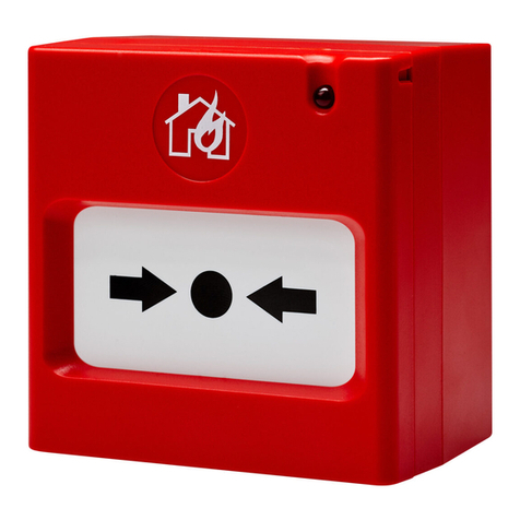
SensoMAG MHB50 is a manual call point for emergency stopping, or
temporary holding and delaying the extinguishing process, providing
time for evacuation of the protected area.
The call point is designed to work with extinguishing fire control
panels and it is suitable for surface indoor mounting. The pressing of
a non-latching push button provides the delaying of the extinguishing
process on the protected area with a time programmed in advance in
the control panel.
SensoMAG MHB50 is equipped with a transparent protective cover
which helps for minimizing the unwanted activation of the call point.
SensoMAG MHB50 is connected to the “HOLD” input of the
extinguishing panel via COM (common), NO (normally open) and NC
(normally closed) changeover contacts.
Working Principle
In case of a fire alarm in the protected site, the user has to lift up the
protective cover and to press the button to provide an extra time for
evacuation. In this way the extinguishing process will be delayed with
a time set in the control panel.
Testing the Call Point Operation
To test the emergency stop manual call point, single press and
release the push button. The “HOLD ACTIVATED” LED on the front
panel of the extinguishing panel will light on in yellow meaning the
HOLD input on the main PCB has been activated.
To return to normal operation mode of the extinguishing system,
reset the panel.
Maintenance and Service
The manufacturer recommends the call point to be inspected for
visible physical damages every week. Test the call point operation as
a part of the whole extinguishing system according the local
regulations in the country.
In case of damage of the protective transparent cover, it can be
easily replaced with a new one.
English Installation Instructions
Общо описание
SensoMAG MHB50 е ръчен бутон, предназначен за аварийно спиране или
временно задържане/забавяне на стартиран процес по пожарогасене, с
което се осигурява допълнително време за евакуация на охранявания
обект.
Бутонът е проектиран за работа с контролни панели за пожарогасене и е
подходящ за стенен повърхностен монтаж в закрити помещения. С
натискане на бутона (без задържане) се осигурява забавяне на поцеса по
пожарогасене с предварително програмирано в панела време.
SensoMAG MHB50 е с фабрично монтиран предпазен прозрачен капак,
осигуряващ защита срещу неволно или нежелано задействане на бутона.
SensoMAG MHB50 се свързва към вход “HOLD” (ЗАДЪРЖАНЕ) на
пожарогасителния панел чрез клеми COM (общ), NO (нормално отворен)
и NC (нормално затворен) контакт.
Принцип на действие
В случай на пожарна аларма в охранявания обект, потребителят може да
осигури допълнително време за евакуация преди стартиране на процеса
по пожарогасене, като повдигне предпазния капак и натисне еднократно
бутона. По този начин процесът на пожарогасене ще се отложи с времето,
което е програмирано в контролния панел.
Тестване за работоспособност
За да тествате работата на SensoMAG MHB50 натиснете еднократно
бутона в средата на работния елемент. Светодиод “HOLD ACTIVATED”
(ЗАДЪРЖАНЕ на гасенето) светва постоянно в жълто на предния панел
на пожарогаситения панел, което означава, че е задействан вход “HOLD”
на основната платка.
За връщане към нормален работен режим на пожарогасителната
система, направете ресет (RESET) на панела.
Поддръжка и сервиз
Производителят съветва да се извършва ежеседмичен оглед за видими
механични повреди на ръчния бутон за аварийно спиране. Тествайте
неговата рабоспособност като част от цялата система за пожарогасене в
съответствие с прилаганите наредби и изисквания на регионално и
местно ниво.
В случай на счупване на защитния предпазен капак той може лесно да се
замени с нов.
Български Инструкция за инсталиране
Indoor Use /
Вътрешен
монтаж
18020879; RevA; 04/2017
SensoMAG MHB50
Emergency stop manual call point
Teletek Electronics JSC
Address: 14A Srebarna Str,
1407 Sofia, Bulgaria
EN 54-11
EN 12094-3
Type B
DoP No: 116
94mm
92mm
60mm
Dimensions / Размери
!
IP40
~173g
Installation / Instalación /
Инсталиране
!
Operating voltage . . . . . . . . . . . . . . . . . . Работно напрежение . . . . . . . . . . 9÷30VDC
Series resistor . . . . . . . . . . . . . . . . . . . . . Сериен резистор . . . . . . . . . . . . . N.A/не
Material (plastic), color. . . . . . . . . . . . . . . Материал (пластмаса), цвят . . . . ABS, blue/син
Type of the оrerating element . . . . . . . . . Тип на работния елемент . . . . . . Button, non-latching/Бутон, без задържане
Dimensions (without protective cover). . . Размери (без предпазен капак). . 90x90x56mm
Dimensions (with protective cover) . . . . . Размери (с предпазен капак) . . . 94x92x60mm
This manual is subject to change without notice! / Производителят си запазва правото на промени без предизвестие!
-10°C ÷ +60°C
(93±3)%@+40°C
2
0.4-2.0mm
Installation Instructions
1. Pick up the cover and take out the kit elements.
2. Mount the base as observe the knockout holes - never locate them at left or right side.
3. Use the special tool to disassemble the front cover from the carrier unit - use the short side
of the tool, fix it to the three holes at the upper side of the front cover. Press down and pull out
the cover from the carrier unit.
4. Pull out with caution the operating element with the button mounted to it from the carrier
unit. The push button is connected to the device PCB. Be careful to not break down the
connection!
5. Connect the installation wires to the call point terminals - see the connection diagrams.
6. Place the carrier unit over the mounting box and use the supplied in the kit screws (M4x8
DIN966) to fix the parts together.
7. Place back the operation element to its place on the carrier unit.
8. Mount the front cover (the transparent protection cover is factory mounted to it).
9. Test the call point functionality and operation.
Инструкции за инсталиране
1.Свалете капака на ръчния бутон и извадете плика с допълнителни елементи.
2. Монтирайте основата към стената, като позиционирате отворите за щуцери отгоре и отдолу - не
монтирайте основата с отворите настрани.
3. С помощта на специализирания ключ демонтирайте предния капак от носещата рамка -
поставете късата страна на ключа в отворите от горната страна на предния капак. Натиснете
надолу, за да избутате палеца и свалете капака.
4. Свалете работният елемент с монтирания бутон към него от носещата рамка - повдигнете
долната му страна и издърпайте внимателно напред. Бутонът е свързан към платката на
устройството чрез кабел с букса. Внимавайте да не го повредите!
5. Свържете инсталационните кабели към клемите на бутона - виж диаграмите на свързване.
6. Използвайте винтовете (M4x8 DIN966) от комплекта с допълнителни елементи, за да фиксирате
носещата рамка към монтажната основа.
7. Монтирайте обратно работния елемент към носещата рамка.
8. Монтирайте предния капак (защитния прозрачен капак е фабрично монтиран към него).
9. Тествайте ръчния бутон за работоспособност.
STRUCTURE / СТРУКТУРА Surface mounting position /
Разположение при монтиране
Testing the operation / Тестване за работоспособност
Connection to an extinguishing fire alarm panel / Свързване към пожарогасителен панел
(1) - Surface wall mounting base.
(2) - Carrier unit.
(3) - PCB with terminals (mounted on the
back of the carrier unit).
(4) - Operating element with mounted non-
latching button. Attention: The button is
connected via terminal junction to the
PCB! Be careful to not break down the
cable during the installation of the call
point!
(5) - Front cover.
(6) - Special tool for disassembling the front
cover from the carrier unit.
(7) - Protective transparent cover (factory
mounted to the front cover). It is replaceable
in case of damage.
(1) - Основа за стенен монтаж.
(2) - Носеща рамка.
(3) - Платка с клеморед (монтирана от
обратната страна на носещата рамка).
(4) - Работен елемент с монтиран бутон (без
задържане). Внимание: Бутонът е
свързан към платката чрез кабел с
букса! Внимавайте да не повредите тази
връзка по време на инсталацията на
бутона!
(5) - Преден капак.
(6) - Специален ключ за демонтаж на
предния капак от носещата рамка.
(7) - Предпазен прозрачен капак (фабрично
монтиран към предния капак). Той може да
се замени с нов в случай на счупване.
NO NC COM
HOLD ACTIVATED
Extinguishing panel indication /
Индикация на
пожарогасителния панел
1. Lift up the protective cover. / Повдигнете защитния капак.
2. Single press and release the non-latching button. / Натиснете
еднократно бутона.
3. The “HOLD ACTIVATED” LED is lighting on in yellow on the front panel of
the extinguishing fire alarm panel. / Светодиод “HOLD ACTIVATED”
(ЗАДЪРЖАНЕ на гасенето) свети постоянно в жълто.
Note: Press “RESET” button of the extinguishing panel to return to Normal
operation mode. / Забележка: Натиснете бутон “RESET” на панела за
пожарогасене за връщане към нормален работен режим.
2.2K2.2K
HOLD
Input
NO Type
(Normal Open)
HOLD
Input
NC Type
(Normal Closed)
NO NONC NCCOM COM
The connection between the extinguishing fire alarm panel and SensoMAG MHB50 call point depends on the type for activation of
the panel’s HOLD input. Before realizing the connection you have to check the type (NO or NC; “open” or “close” action is set for
activation) of the HOLD input of the extinguishing panel. Note: In operation with IVY Extinguishing Fire Alarm panel, set the HOLD
input activation with J4 jumper on the main PCB of the panel. /
Свързването между пожарогасителния панел и SensoMAG MHB50 ръчен бутон зависи от типа на активиране на вход HOLD
на панела. Преди реализиране на връзката трябва да проверите типа (NO или NC; настройка за „отварящо“ или
„затварящо“ действие при активиране) на вход HOLD на гасителния панел. Забележка: При работа с Пожарогасителен
панел IVY, настройте типа на активиране с джъмпер J4 на основната платка на панела.
MHB50 MHB50
Extinguishing
Panel
Extinguishing
Panel

Other Teletek electronics Security System manuals

Teletek electronics SF 120 User manual

Teletek electronics

Teletek electronics SF 120 User manual

Teletek electronics Natron WE-C User manual

Teletek electronics

Teletek electronics Natron WE-C User manual

Teletek electronics SensoIRIS MCP150MR User manual

Teletek electronics

Teletek electronics SensoIRIS MCP150MR User manual

Teletek electronics CA62 Assembly instructions

Teletek electronics

Teletek electronics CA62 Assembly instructions

Teletek electronics SensoMAG S30 User manual

Teletek electronics

Teletek electronics SensoMAG S30 User manual

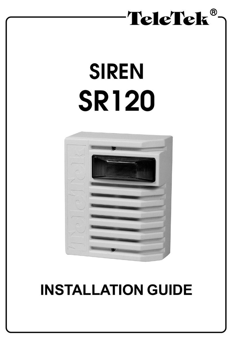
Teletek electronics SR 120 User manual

Teletek electronics

Teletek electronics SR 120 User manual

Teletek electronics CA824 User manual

Teletek electronics

Teletek electronics CA824 User manual

Teletek electronics BRAVO User manual

Teletek electronics

Teletek electronics BRAVO User manual

Teletek electronics CA824 User manual

Teletek electronics

Teletek electronics CA824 User manual

Teletek electronics AVA Assembly instructions

Teletek electronics

Teletek electronics AVA Assembly instructions

Teletek electronics CA864 User manual

Teletek electronics

Teletek electronics CA864 User manual

Teletek electronics BRAVO User manual

Teletek electronics

Teletek electronics BRAVO User manual

Teletek electronics AVA User manual

Teletek electronics

Teletek electronics AVA User manual

Teletek electronics SensoMAG R20 User manual

Teletek electronics

Teletek electronics SensoMAG R20 User manual

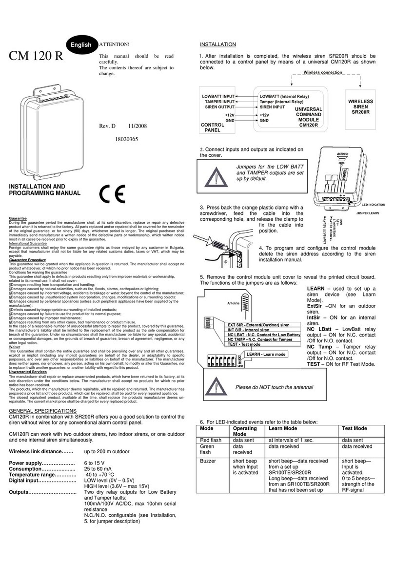
Teletek electronics CM 120 R Assembly instructions

Teletek electronics

Teletek electronics CM 120 R Assembly instructions

Popular Security System manuals by other brands

Sygonix 1527193 operating instructions

Sygonix

Sygonix 1527193 operating instructions

Technaxx Maxi Security Kit PRO FullHD 1080P TX-50 user manual

Technaxx

Technaxx Maxi Security Kit PRO FullHD 1080P TX-50 user manual

AJAX DoubleButton user manual

AJAX

AJAX DoubleButton user manual

DSC PowerSeries installation guide

DSC

DSC PowerSeries installation guide

MAGNASPHERE HSS-L2S-000 Series installation instructions

MAGNASPHERE

MAGNASPHERE HSS-L2S-000 Series installation instructions

VADDIO WALLVIEW CCU H700 Installation and user guide

VADDIO

VADDIO WALLVIEW CCU H700 Installation and user guide

Minut MT-P2 manual

Minut

Minut MT-P2 manual

Bpt E/310.01 installation instructions

Bpt

Bpt E/310.01 installation instructions

Steren CCTV-500 manual

Steren

Steren CCTV-500 manual

GWAZA 15152 Product information

GWAZA

GWAZA 15152 Product information

Larson Electronics SLEDB-110V-6C instruction manual

Larson Electronics

Larson Electronics SLEDB-110V-6C instruction manual

Pyronix PCX 256 Programming manual

Pyronix

Pyronix PCX 256 Programming manual

Whelen Engineering Company WS295HFS1 Series Installation & operating manual

Whelen Engineering Company

Whelen Engineering Company WS295HFS1 Series Installation & operating manual

GE CareGard quick reference

GE

GE CareGard quick reference

Atlantis A13-A750G-AK user manual

Atlantis

Atlantis A13-A750G-AK user manual

Cooper Security I-SD01 Installation and programming guide

Cooper Security

Cooper Security I-SD01 Installation and programming guide

Klaxon GP10 Installation and Maintenance

Klaxon

Klaxon GP10 Installation and Maintenance

NuTone la600wh Installation & operating instructions

NuTone

NuTone la600wh Installation & operating instructions

manuals.online logo
manuals.online logoBrands
  • About & Mission
  • Contact us
  • Privacy Policy
  • Terms and Conditions

Copyright 2025 Manuals.Online. All Rights Reserved.